
The Refrigeration Compressor
The only major moving component in the circuit — where most of the maintenance and nearly all of the noise lives.
Key Principles at a Glance 5 points
- The compressor is sized for the pull-down condition, not normal running — drive motors carry a 25 % allowance, so they spend most of their life below 80 % rated output at poor power factor.
- Modern machines are single acting with the crankcase at suction pressure because double-acting designs could not be kept gas-tight at the piston rod.
- A compressor starts unloaded so as to reduce starting torque on the motor; oil pump pressure then depresses the valve lifters and loading begins.
- The lube oil differential cut-out compares oil pressure with suction pressure and trips below 1.2 bar, requiring a manual reset.
- A ruptured bursting disc is indicated by suction and discharge pressures being about equal.
1. What the Engineer Must Understand
The maker's manual and the class rules override. Never run a compressor with a suspected valve or seal defect "until we get to port" without recording the decision and informing the Chief Engineer.
- The compressor's job is to accept the low-pressure dry gas from the evaporator and raise its pressure to that of the condenser.
- In raising the pressure it raises the saturation temperature above that of the sea water or air cooling the condenser. It also promotes circulation of the refrigerant by pumping it around the system.
- Compressors are either positive displacement (piston, rotary vane, rolling piston, screw, scroll) or dynamic (centrifugal).
- Reciprocating compressors are in the majority in marine applications, because they are most suited to the low specific volume vapours and large pressure differentials characteristic of all the main refrigerants.
The compressor is sized for the pull-down condition, not the normal running condition. When first started, the system operates at a higher suction temperature and pressure than normal and therefore a higher discharge pressure, taking considerably more power. Drive motors are sized with an allowance of 25 % for this pull-down power. As a result the motor runs for the greater part of its life at something under 80 % rated output, at lower efficiency, low running current and poor power factor. Electrical protection must take this into account and power factor correction should be fitted on large motors.
2. The Reciprocating Compressor
The working cycle
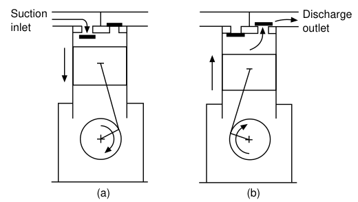
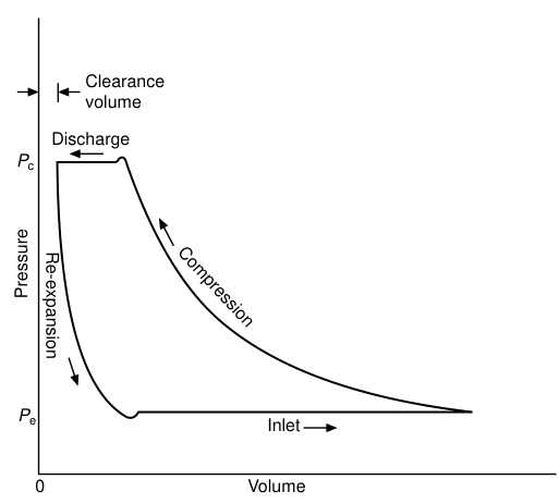
It works on a two-stroke cycle. As the piston descends on the suction stroke, the internal pressure falls until it is lower than that in the suction inlet pipe and the suction valve opens to admit gas from the evaporator. At the bottom of the stroke the valve closes and the compression stroke begins. When the cylinder pressure is higher than that in the discharge pipe, the discharge valve opens and the compressed gas passes to the condenser. Clearance gas left at the top of the stroke must re-expand before a fresh charge can enter.
Historical note that explains the present design
The first commercial piston compressors evolved from steam engines. Construction at first was double acting, but there was difficulty in maintaining gas-tightness at the piston rod, so the design evolved into a single-acting machine with the crankcase at suction inlet pressure, leaving only the rotating shaft as a possible source of leakage — sealed with a packed gland. This is why modern machines are single acting with the crankcase at suction pressure.
Multicylinder construction
Compressors for higher capacity used to be made larger — cylinder bores up to 375 mm at speeds up to 400 rev/min — with heavy, cumbersome components. To take advantage of larger-scale production methods and provide interchangeability of parts, modern compressors tend to be multicylinder, with bores not larger than 175 mm and running at higher shaft speeds. Machines of four, six and eight cylinders are common, arranged in a multibank configuration with two, three or four connecting rods on the same throw of the crankshaft, to give a short, rigid machine.
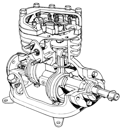
The maintenance advantage: this construction gives a large number of common parts — pistons, connecting rods, loose liners and valves — across a range of compressors, and such parts can be replaced if worn or damaged without removing the compressor body from its installation.
The modern machine described
- Almost all modern machines are motor driven, high speed (up to 30 rev/s), single acting types which have adopted many improvements in line with the automobile industry.
- The only gland seal is the crankshaft seal where the shaft emerges from the crankcase, such seal being mainly subject to suction pressure.
- Multi-cylinder in-line types are popular, but there is increasing use of Vee and modified W designs.
- Pistons are usually of the trunk type, two or three compression rings and a lower oil seal ring.
- The suction valve may be located in the head of the piston or in the cylinder head; the most modern arrangements have suction and discharge valves in a valve plate in the cylinder head.
- Compressor bodies are close-grained castings of iron or steel.
- The crankshaft can be eccentric-drive type or the more conventional crank and connecting rod, lubrication being either dip and splash or forced with a pump.
- Modern valves are of the reed or disc type mounted in the head, of high-grade steel on stainless steel seats, with a usual lift of about 2 mm in average sizes.
- The discharge valve retainer is normally held down to a set position by heavy springs. If oil or liquid is discharged, the retainer lifts giving extra valve lift, so reducing over-pressure. Cylinder relief valves and over-pressure cut-outs are also standard practice fittings.
- With valve-in-piston-head types the piston is often long and cut away at the side to the centre, so suction vapour enters there and there is no connection through to the crankcase, which reduces oil pumping effects.
- Screw-type service valves are double seated, full open or full shut, which allows easy gland packing changes.
- All reciprocating compressors should have the minimum reasonable piston clearance — 1.5 mm as a maximum — so as to give maximum efficiency.
Valve types
Piston compressors may be classified by the type of valve, which depends on size, since a small swept volume requires a proportionally small inlet and outlet gas port.
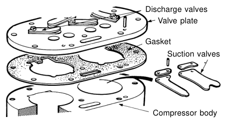
- Smallest compressors — spring steel reed valves, both inlet and outlet in the cylinder head, arranged on a valve plate.
- Above about 40 mm bore — the port area available within the head size is insufficient for both inlet and outlet valves, so the inlet is moved to the piston crown or to an annulus surrounding the head. The discharge valve remains in the central part of the cylinder head.
- In most makes both types of valve cover a ring of circular gas ports and are made in annular form — generally termed ring plate valves. Made of thin spring steel or titanium, limited in lift and damped by light springs to assist even closure and lessen bouncing.
- An alternative design uses a conical discharge valve in the centre of the cylinder head with a ring plate suction valve surrounding it — used in compressor bores up to 75 mm.
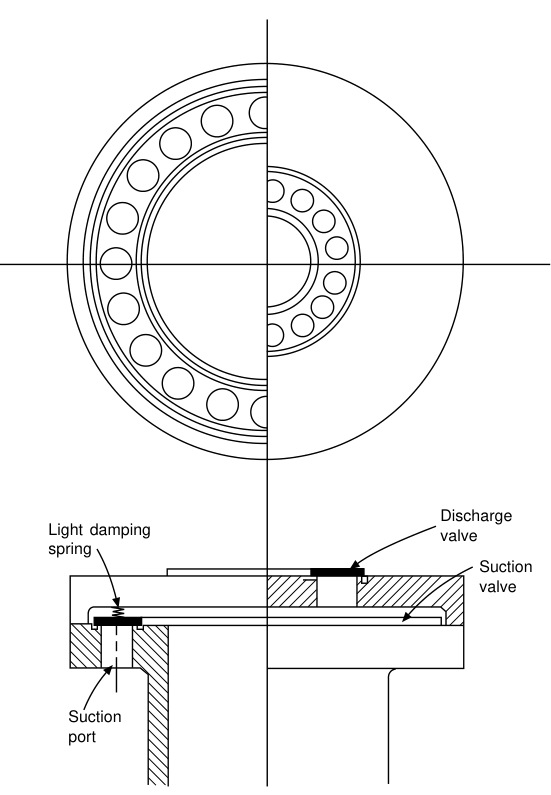
Although intended to handle only dry gas, liquid refrigerant or traces of oil may sometimes enter the cylinder and must pass out through the discharge valves. These may be arranged on a spring-loaded head which will lift and relieve excessive pressures. Some makes also have an internal safety valve to release gas pressure from the discharge back to the suction inlet.
The shipboard V/W machine
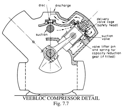
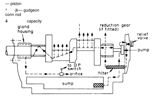
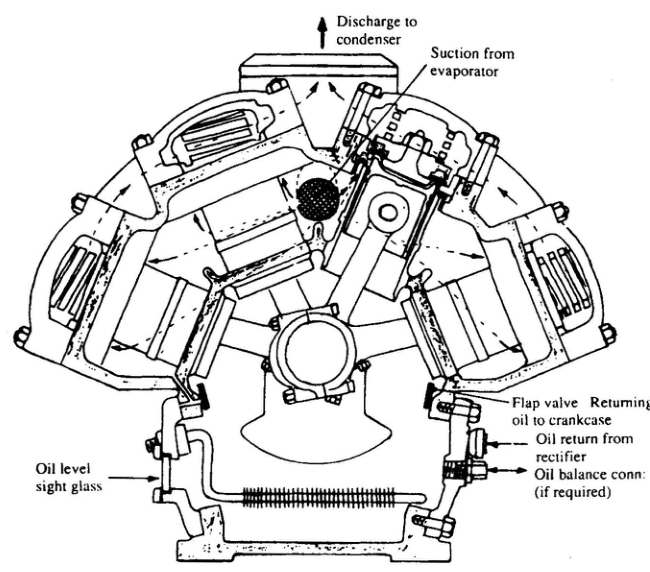
Construction of the V/W machine:
- In general there are 4, 6 or 8 cylinders radially round the upper half of the cast iron crankcase, with from two to four connecting rods from each of two crank throws.
- The aluminium piston is fitted with two compression rings and one scraper ring.
- A differential oil pressure switch and an overload electrical switch protect the machine from low oil or high vapour pressure.
- The discharge valve cage is spring-loaded to lift in case of liquid carry-over, and there is an over-pressure nickel bursting disc to relieve excess discharge pressure to the suction side.
- Connecting rods are aluminium with steel-backed white metal bearings; the crankshaft is SG iron.
A large cargo machine described:
- Vertical in-line type for systems cooling domestic store rooms; for large cargo installations the banks of cylinders are arranged in V or W configuration.
- Each crank carries the bottom ends of four pistons. Older machines have cast iron pistons; modern compressors have aluminium alloy pistons. Piston rings may be plain cast iron, but special rings having phosphor-bronze inserts are sometimes fitted — these assist when running in.
- Connecting rods are H-section steel forgings with white-metal-lined steel small-end bushes.
- Liners are high tensile cast iron; crankcase and cylinders are a one-piece iron casting.
- The two-throw crankshaft is spheroidal graphite cast iron. Main bearings are white-metal-lined steel shells.
- Gas from the evaporator passes through a strainer housed in the suction connection of the machine, lined with felt to trap scale and other impurities scoured from the system by the refrigerant during the running-in period.
- Freons are "searching" liquids, similar to carbon tetrachloride — they tend to clean the circuit, but the impurities will cause problems unless removed by strainers.
- Any oil returning with the refrigerant drains to the crankcase through the flaps at the side of the cylinder space.
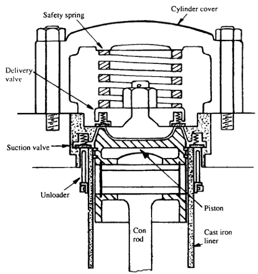
- The delivery valve is held in place by a safety spring which allows the complete valve to lift in the event of liquid carry-over.
- The delivery valve is an annular plate with its inside edge seated on the mushroom section and its outside edge on the suction valve housing.
- The suction valve passes gas from the suction space around the cylinder.
3. Capacity Reduction (Unloading)
A refrigeration system is designed to have a maximum duty to balance a calculated maximum load, and for much of its life may work at some lower load. Such variations require capacity reduction devices — originally by speed control (when steam driven) or in the form of bypass ports in the cylinder walls.
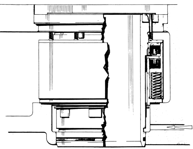
Methods in use:
| Method | How it works |
|---|---|
| Valve lifting (unloading) | The ring plate suction valve at the crown of a loose liner is lifted by mechanical systems actuated by the pressure of the lubricating oil and controlled by solenoid valves. Typically an annular piston operates push rods under the valves. A multicylinder machine can have any number of cylinders unloaded — and will start unloaded until the build-up of oil pump pressure depresses the valve lifters |
| Bypass across the head | A valved bypass across inlet and outlet ports in the cylinder head, or a variable clearance pocket in the head |
| External bypass piping | Capacity reduced by external bypass (see also hot gas injection) |
| Two-speed motors / electronic speed variation | Down to a lower limit dictated by the inbuilt lubrication system |
| Steam turbine drive | Speed control within the limits of the prime mover |
Reed's puts it in shipboard terms: provision is made for reducing the capacity of the machine either manually or automatically. Capacity reduction gear lifts and holds open the alloy steel suction valves of a specified number of cylinders; this is operated by oil pressure on a servo piston in the automatic type. This can also provide total or partial unloading for easier starting.
For the marine machine: for unloading a mechanism holds the valve open so that gas is able to flow freely in and out through the valve without compression. The collar holding the fingers is fitted around the liner and moved up or down by a yoke operated from a cam or servo cylinder.
Compressors will tend to overheat under low mass flow conditions resulting from abnormally low suction pressures or lengthy running with capacity reduction. Detectors may need to be fitted to warn against this condition.
4. Cooling
- Cold suction gas provides cooling for the compressor and is sufficient to keep small machines at an acceptable working temperature.
- Refrigerants having high discharge temperatures (mainly ammonia) require the use of water-cooled cylinder heads.
- Oil coolers are needed under some working conditions specified by the manufacturer — water cooled, or taking refrigerant from the system.
For low suction temperature operation (say −20 °C or lower) and high discharge temperature (say 30 °C or higher) excessive temperatures may be reached in the reciprocating compressor. This is even more liable to occur in the unloaded state than in the loaded state, and is most often found in the fast running smaller bore-stroke size of compressor. In certain cases an oil cooler must be used, particularly when automatic unloading is required.
Crankcase heaters are usually fitted for use with the machine stopped; this prevents formation of liquid refrigerant and oil frothing on starting. Auto compressors should be fitted with solenoid operated liquid stop valves.
5. Strainers and Lubrication
- Incoming gas may contain particles of dirt from within the circuit, especially on a new system. Suction strainers or traps are provided to catch such dirt and will be readily accessible for cleaning on the larger machines.
- All but the smallest compressors have a strainer or filter in the lubricating oil circuit. Strainers within the sump are commonly of the self-cleaning slot disc type. Larger machines may also have a fabric throwaway filter, as in automobile practice.
- Reciprocating compressors operate with a wet sump, having splash lubrication in the small sizes but forced oil feed with gear or crescent pumps on all others. A sight glass is fitted at the correct working oil level and a hand pump may be fitted to permit addition of oil without stopping or opening the plant, the sump being under refrigerant gas pressure.
Crankcase heaters — why they matter
When the compressor is idle the lubricating oil may contain a certain amount of dissolved refrigerant, depending on the pressure, temperature and the refrigerant itself. At the moment of starting, the oil will be diluted by this refrigerant and, as the suction pressure falls, gas will boil out of the oil, causing it to foam. To reduce this solution of refrigerant in the oil to an acceptable factor, heating devices are commonly fitted to crankcases and remain in operation whenever the compressor is idle.
Foaming of oil → reduced oil pressure → oil pressure cut-out trips → compressor starts and stops immediately. Check the crankcase heater.
The rotor-type oil pump
Oil is supplied by a rotor type of pump in which the inner rotor has one less tooth than the outer rotor, and oil is induced to flow between the two rotors.
The gear-pump arrangement and its settings
Oil is supplied to the bearings and crankshaft seal by a gear pump driven from the crankshaft. The oil is filtered through an Auto-Klean strainer and/or an externally mounted filter with isolating valves. A pressure gauge and sight glass are fitted, and protection against oil failure is provided by a differential oil pressure switch.
- Oil pressure is about 2 bar above crankcase pressure, and the differential oil pressure switch is necessary to compare oil pressure with that of the gas in the crankcase.
- There is a relief valve in the oil system set to about 2.5 bar above crankcase pressure.
- Cylinder walls are splash lubricated and some of the oil is carried round with the refrigerant.
The lube oil differential pressure cut-out compares lube oil pressure and compressor suction pressure. If the differential pressure falls below 1.2 bar, the compressor trips and requires a manual reset to restart. A time delay is built into the circuit to allow sufficient time for the lube oil pressure to build up while starting.
6. Shaft Glands and Motors
Open compressors
Compressors having external drive require a gland or seal where the shaft passes out of the crankcase, and are termed open compressors. They may be belt driven or directly coupled to the shaft of the electric motor or other prime mover.
The usual form of shaft seal comprises a rotating carbon ring in contact with a highly polished metal facing ring, the assembly being well lubricated. The carbon ring is spring-loaded to maintain contact under all working crankcase pressures, and to allow for slight movement of the shaft.
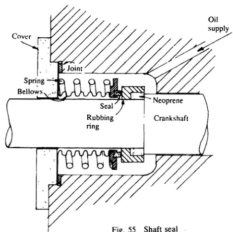
Where motor and compressor casings are separate, a mechanical seal is fitted around the crankshaft at the drive end of the crankcase. It consists of a rubber ring with an oil-hardened face against which the seal operates. The seal is pressed on to the face by the tensioning spring, and being attached to a bellows it is self-adjusting. The rubbing ring incorporates a neoprene or durene ring which seals it to the shaft.
The mechanical seal is lubricated from the compressor system and can give trouble if there is insufficient or contaminated oil in the machine. Undercharge may be caused by seal leakage due to oil loss. When testing the seal for leakage, turn the shaft to different positions if the leak is not apparent at first.
Practical tip: where gas is detected at the shaft gland of an open compressor which is not turning, run the compressor for a short time to re-lubricate the gland — the leak may then cease.
Hermetic and semi-hermetic drives
The possible slight leakage of refrigerant through a shaft gland may be acceptable with a large system but would lead to early malfunction of a small circuit. The wide use of small refrigeration systems has led to methods of avoiding shaft seals, provided the working fluid is compatible with the materials of electric motors and has a high dielectric strength.
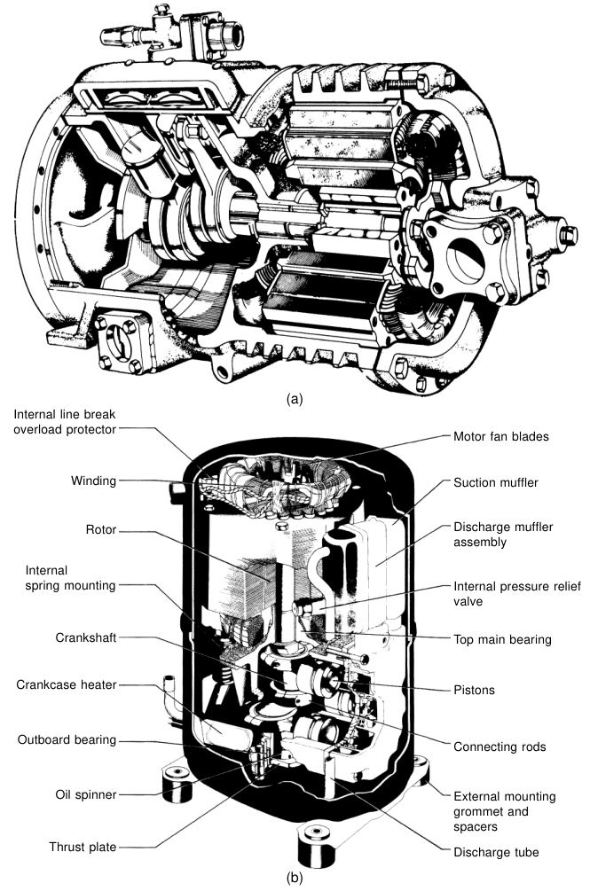
- Semi-hermetic (accessible-hermetic): the rotor of the drive motor is integral with an extended crankshaft and the stator is fitted within an extension of the crankcase. Suction gas passes through the motor itself to remove motor waste heat. Induction motors only can be used, with any starting switches outside the crankcase, since any sparking would lead to decomposition of the refrigerant. Electrical leads pass through ceramic or glass seals.
- Fully hermetic: motor and all working parts sealed within a steel shell, so not accessible for repair or maintenance. Application is limited by the amount of cooling by the incoming cold gas, heat loss from the shell, and the possible provision of an oil cooler.
The failure of an inbuilt motor will lead to products of decomposition and serious contamination of the system, which must then be thoroughly cleaned. Internal and external motor protection devices are fitted with the object of switching off the supply before such damage occurs.
7. Other Compressor Types
Rotary
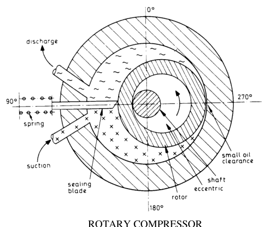
The timing is clear from the geometry: at the position shown the discharge and suction strokes are half completed (270°). At 0° discharging at compression stroke, induction at suction stroke. At 90° start of compression and end of suction. At 180° compression taking place and the suction stroke has just started. Thus the leading flank of the rotor acts as the discharger and the lagging flank acts as the inductor.
Such compressors mainly find application in household and domestic units, but modern practice is extending their use to cargo purposes. A variation is a multiblade type whereby the eccentric rotor contains spring-loaded blades (or relies on centrifugal force). When any rotary compressor is not in use the oil film between eccentric rotor and cylinder is broken, which means pressure equalisation and easy starting, but requires the fitting of a non-return valve in the suction line.
Sliding vane and rolling piston
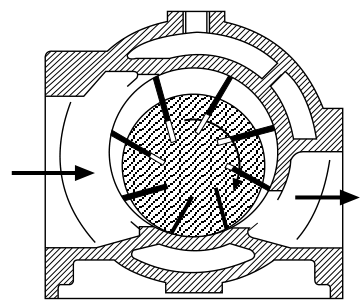
- The volumes between an eccentric rotor and sliding vanes vary with angular position, to provide a form of positive displacement compressor. Larger models have eight or more blades and do not require inlet or outlet valves. Blades are held in close contact with the outer shell by centrifugal force, and sealing is improved by injection of lubricating oil along the length of the blades.
- Rotating vane machines have no clearance volume and can work at high pressure ratios.
- Larger rotating vane compressors are limited by the stresses set up by the thrust on the tips of the blades, and are used at low discharge pressures such as the first stage of a compound cycle.
- Smaller compressors up to 110 kW cooling capacity are available for the full range of working pressures, incorporating a spring-loaded safety plate to relieve excess pressure if liquid refrigerant enters.
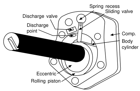
- Sliding vane or rolling piston compressors have one or two blades which do not rotate but are held by springs against an eccentric rotating roller. These require discharge valves. Developed extensively for domestic appliances and packaged air-conditioners, up to 15 kW cooling duty.
Screw
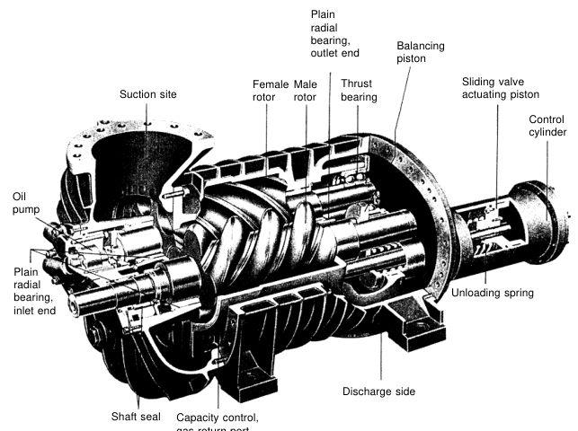
The screw compressor can be visualised as a development of the gear pump. For gas pumping the rotor shapes are modified to give maximum swept volume and no clearance volume where the rotors mesh, and the pitch of the helix is such that the inlet and outlet ports are arranged at the ends instead of at the side. The solid portions of the screws slide over the gas ports to separate one stroke from the next, so that no extra inlet or outlet valves are needed.
- The usual form has twin meshing rotors on parallel shafts. As they turn, the space between two grooves comes opposite the inlet port and gas enters. On further rotation this pocket is cut off from the inlet and moved down the barrels; a meshing lobe of the male rotor compresses the pocket, and the gas is finally released at the opposite end when the exhaust port is uncovered.
- Sealing between the working parts is usually assisted by injection of oil along the length of the barrels. This extra oil must be separated from the discharge gas, then cooled and filtered before returning to the lubrication circuit.
- The other form has a single grooved rotor, with rotating star tooth seal vanes to confine the pockets. Gas sealing at these surfaces is effected by injecting a small amount of liquid refrigerant, which obviates the need for the oil lubrication and cooling circuit, with its pumps, and leaves the compressor and the circuit oil-free.
- Screw compressors have no clearance volume, and may work at high compression ratios without loss of volumetric efficiency. In all screw compressors the gas volume will have been reduced to a pre-set proportion of the inlet volume by the time the outlet port is uncovered — this is the built-in pressure ratio. At that point the gas within the screws is opened to condenser pressure, and gas will flow inwards or outwards through the discharge port if the pressures are not equal.
- The absorbed power is at its optimum only when the working pressure ratio equals the built-in pressure ratio. This loss of efficiency is acceptable since the machine has no valves and no working parts other than the screws and sealing vanes.
- Capacity reduction is effected by a sliding block covering part of the barrel wall, which permits gas to pass back to the suction, so varying the working stroke. Variation down to 10 % of maximum is usual.
Reed's adds: clearance between lobe screws and casing is kept to a minimum with sealing strips and oil film. To reduce capacity, sliding sleeves around the barrel can be moved axially to bring the outlet port nearer to the inlet port.
Scroll
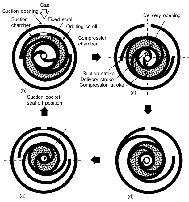
A positive displacement gas compressor constructed with a pair of nesting volutes, one stationary and one orbiting. Gas enters from the surrounding enclosure, is trapped between the volutes and moved inwards until it is finally forced out through the central discharge port. Owing to the close manufacturing tolerances the scroll compressor is built only in hermetic enclosed models. The dynamic and gas pressure loads are balanced so that it is free of vibration. Cooling capacities up to 60 kW, with larger sizes in development. Capacity control is achieved by varying the compressor speed by means of an inverter motor.
Centrifugal (dynamic)
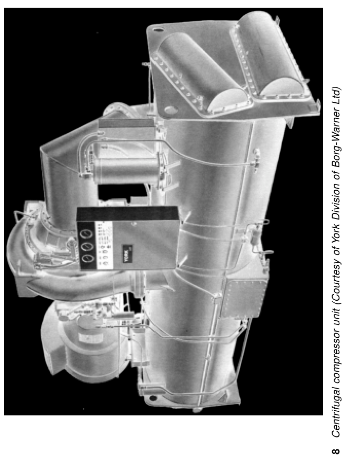
- Dynamic compressors impart energy to the gas by velocity or centrifugal force and then convert this to pressure energy. Suction gas enters axially into the eye of a rotor with curved blades and is thrown out tangentially from the blade circumference.
- The energy given to the gas depends on the velocity and density of the gas. Since density is fixed by the working conditions, the design performance is decided by the rotor tip speed. Owing to the low density of gases used, tip speeds up to 300 m/s are common.
- At 2900 rev/min a single-stage machine would need an impeller 2 m in diameter — so drives are geared up from standard-speed motors or the supply frequency is changed to get higher motor speeds. On single-stage centrifugal compressors for air-conditioning duty, rotor speeds are usually about 10 000 rev/min.
- Gas may be compressed in two or more stages with impellers on the same shaft — a compact tandem arrangement, gas from one stage passing directly to the next. The steps of compression are not very great and, if two-stage is used, the gas may pass from the first to the second without any intercooling.
- Centrifugal machines can be built for industrial use with ammonia and other refrigerants, with up to seven compression stages. With the high tip speeds in use, it is not practical to build a small machine — the smallest available centrifugal compressor for refrigeration duty has a capacity of some 260 kW. Semi-hermetic compressors are made up to 7000 kW and open drive machines up to 21 000 kW.
- Systems of this size require large-diameter refrigerant suction and discharge pipes.
Reed's adds: centrifugal machines are best suited to low differential pressure, high volume capacity work such as air conditioning. Capacity reduction is effected by directional blades at the rotor inlet port. Efficiency is increased if interstage flash vapour formed during liquid expansion is returned to an appropriate stage of the compressor.
8. Compressor Performance Figures Worth Remembering
An eight-cylinder machine of 178 mm bore and 140 mm stroke running at about 12.5 rev/s would require a drive of about 90 kW for a refrigerating capacity of about 320 kJ/s with Freon 12 refrigerant.
It is also noted that for suction pressures below atmospheric (with say Freon 12) the risk of air leakage is an important consideration.
9. Compressor Summary Table
| Type | Clearance volume | Valves | Typical marine duty | Capacity control |
|---|---|---|---|---|
| Reciprocating | 4–7 % swept volume | Reed / disc / ring plate | Cargo, domestic, most marine plant | Valve lifting (oil pressure), bypass, speed |
| Rotary vane | None | None (larger); discharge valve (rolling piston) | Small domestic to 110 kW | Speed |
| Screw | None | None | Cargo, large commercial | Sliding block/sleeve, to 10 % |
| Scroll | Small | None | Hermetic packages to 60 kW | Inverter speed |
| Centrifugal | — | None | Air conditioning, ≥260 kW | Inlet guide vanes, interstage flash return |