
Controls, Safety Devices and Circuit Components
The compressor and the four main components do the work; everything here decides when they do it and what stops them when something is wrong.
Key Principles at a Glance 5 points
- A system needs only four components — evaporator, compressor, condenser and expansion valve; everything else is fitted for ease, economy and safety of operation.
- The HP cut-out needs only to be about 2 bar above expected summer pressure, yet is often set as much as 8 bar higher — at which point it gives no warning until the fault is serious.
- A high-pressure switch must be reset manually, because excess pressure indicates a malfunction — usually a condenser fault or a wrongly closed valve.
- The oil safety cut-out is a differential switch with a time delay: it senses oil pump outlet minus suction, and trips below 1.2 bar, requiring a manual reset.
- A de-energized solenoid valve is closed, which is why loss of power shuts the liquid line — and why the compressor pumps down the evaporator before it stops.
1. The Four Essential Components and Everything Else
The maker's manual and the SMS override. Safety controls must be checked at least once a year — for correct setting and correct operation. Never defeat, lock out or re-set a safety control without investigating why it operated.
A refrigeration system can be built with only four essential components: the evaporator, the compressor, the condenser and the expansion valve. For ease, economy and safety of operation, and to assist the maintenance function, other system controls and components will be fitted.
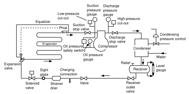
This diagram is the one to be able to draw from memory. It contains every device discussed in this topic.
2. The Automatic Freon System
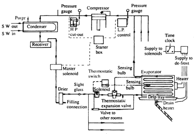
The circuit contains the basic compressor, condenser, expansion valve and evaporator, plus the controls for automatic operation.
How it works, step by step:
The pressure gauge on the compressor discharge shows the gas pressure and also has marked on it the relative condensing temperature. This is not the actual temperature of the gas, which is higher and shown by the thermometer. The pressure gauge should show a pressure with an equivalent temperature about 7 or 8 °C above the sea water inlet.
3. The Direct Expansion Unit
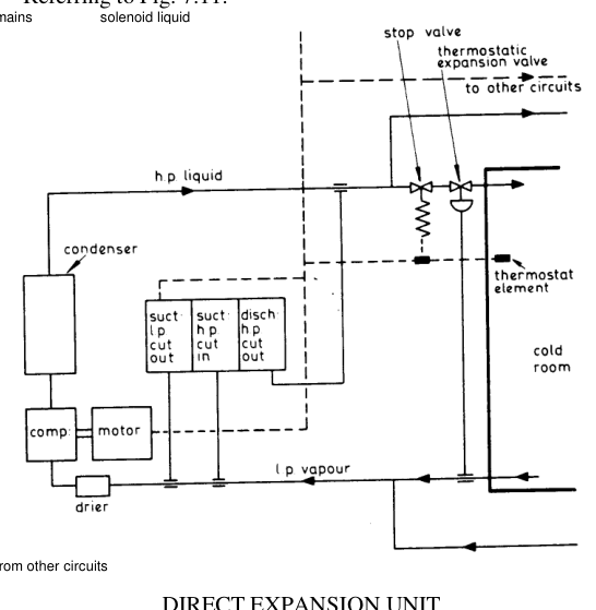
The control automation required is: (1) start, (2) stop, (3) expansion valve, (4) emergency cut-out, (5) cooling air or water circulation, (6) oil separation, (7) liquid in suction line. Obviously this is closely related to electrical control.
- The compressor is started and stopped by a thermal element pressure switch. An emergency pressure cut-out is provided, and the expansion valve is of the thermostatic control type.
- The function of the solenoid liquid stop valve is to isolate different circuits and to shut just before the machine cuts out, so that the compressor clears the suction line before it stops. This prevents liquid knock when restarting.
- When there are a number of circuits — meat, fish, veg rooms, ice tanks, ready-use chambers, etc. — each circuit is a tapping off the main line.
- Each circuit has its own thermostatic expansion valve and solenoid stop valve. When one chamber is cooled the thermostat shuts the liquid stop valve and cuts out that chamber only. This happens progressively to all circuits, and when all circuits are cut out the rapid drop in suction pressure will cut out the compressor.
4. Pressure Switches
4.1 High-pressure cut-out
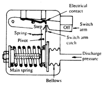
High-pressure cut-outs are fitted to all but the smallest of systems. The compressor outlet pressure is brought to one side of a bellows or diaphragm and balanced by an adjustable spring. A scale on the control indicates the pressure setting to commercial accuracy and is checked on commissioning. If the spring pressure is overcome, the switch will open and stop the compressor.
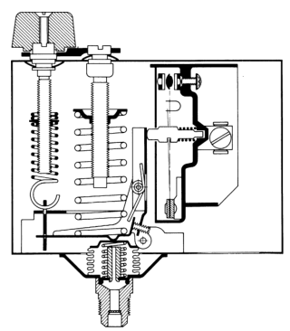
The mechanical description:
The bellows in the cut-out is connected by a small-bore pipe between the compressor discharge and the condenser. The bellows tend to be expanded by the pressure and this movement is opposed by the spring. The adjustment screw is used to set the spring pressure. During normal system operation the switch arm is held up by the switch arm catch and holds the electrical contact in place. Excessive pressure expands the bellows and moves the switch arm catch around its pivot. The upper end slips to the right of the step and releases the switch arm, so breaking the electrical contact and causing the compressor to cut out. The machine cannot be restarted until the trouble has been remedied and the switch re-set by hand.
Setting philosophy — an important operational point:
- The cut-out point only needs to be some 2 bar higher than the expected summer operating pressure, but there is a tendency to set such controls much higher — sometimes as much as 8 bar above summer pressures. At this setting the user will not get a warning of abnormal running until the fault has reached serious proportions.
- Since excess pressure indicates malfunction of part of the system — usually a condenser fault or incorrect closure of a valve — the high-pressure switch should be reset manually, not automatically.
- Where the refrigeration system is providing an essential service which should not be interrupted, one high-pressure switch may be set at a warning level and operate an alarm, without stopping the compressor. A second switch, set somewhat higher, will stop the equipment if this warning is ignored and if excessive pressures are reached.
- All high-pressure cut-outs should be checked at least once a year, for correct setting and operation.
Shipboard setting: the HP cut-out is fitted at the delivery of the compressor. If the compressor delivery pressure increases above the set value the compressor trips. It requires a manual reset to start the compressor.
4.2 Low-pressure cut-out
Abnormally low suction pressures will lead to high discharge temperatures, owing to the high compression ratio, and possible malfunction of other components. Air cooling coils may frost excessively, or water chillers freeze. A low-pressure cut-out switch is usually fitted to stop the compressor under these circumstances.
- Settings may be 0.6–1.0 bar below the design evaporator pressures, but depend very much on the type of system.
- The cut-out setting should be above atmospheric pressure if possible, to avoid the ingress of air through any leaks.
- Abnormally low pressure may not be an unsafe condition, and the low-pressure switch may be automatic reset, closing again at a pressure corresponding to a temperature just below that of the load.
- If a plant has been shut down long enough for all pressures to equalise and is then restarted, the suction pressure will pull down below normal until the liquid refrigerant has begun to circulate. Under such circumstances the low-pressure switch may operate. This is a normal occurrence, but may require the addition of a delay timer to prevent frequent starting of the compressor motor.
Shipboard setting: the LP cut-out trips the compressor in case the suction pressure drops below the set value. In most of the plants it is used for starting and stopping the compressor to maintain the temperatures.
4.3 The pump-down circuit
A low-pressure switch can also be used in conjunction with a thermostat and a solenoid valve in the pump-down circuit.
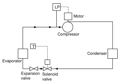
In this method of control the thermostat does not stop the compressor but de-energizes the liquid line solenoid valve to stop the supply of refrigerant to the evaporator. The compressor continues to run and pumps down the evaporator until stopped by the low-pressure switch. When the thermostat again calls for cooling, it opens the solenoid valve, liquid enters the evaporator and the low-pressure switch will close again to restart the compressor.
This method is used to ensure that the evaporator is kept clear of liquid when the plant is off. If there is any leak at the solenoid valve, it will cause the compressor to restart periodically to remove the surplus liquid from the coil.
4.4 The LP controller mechanism
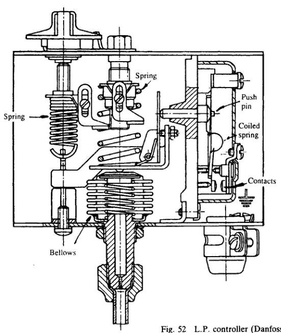
The low pressure control stops the compressor at low suction pressure caused by closure of all cold compartment solenoids. When the pressure in the compressor suction rises due to solenoid opening, the L.P. control restarts the compressor.
The controller shown is of the Danfoss type, operated through a bellows. The spring on the left is for the stopping pressure and that on the right for starting. The push pin operates the switch through a copper plate with a coiled spring between the two tongues. With the contacts open the spring is coiled as shown. Outward movement of the pin compresses the spring and finally tips it to the position where the contacts close.
The two springs are the reason the LP controller has a differential — one sets the cut-out pressure, the other the cut-in pressure. This differential is what prevents the compressor short-cycling.
4.5 The electrical control switch
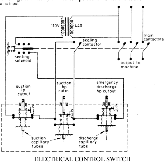
The capillary tubes are usually filled with a volatile liquid (or the refrigerant itself) so that temperature variations cause pressure variations on the flexible metallic bellows. The motion of the bellows operates the trip switches.
- As the temperature of the suction line increases, the bellows pressure increases against the spring compression upwards and closes the selector switch (hp cut in at centre) at say 2 bar, so cutting in the motor.
- With the compressor running the suction temperature falls and hence the bellows pressure falls. This action against a tensile spring will eventually open the other selector switch (lp cut out at left) at say 1 bar, so cutting out the motor and compressor.
- The differential between these two is set for reasonable running.
- The emergency hp cut-out, to operate if cooling failure and pressure build-up occurs, works to open the switch as for cut-out action.
- The sealing contactor maintains the electrical circuit when the hp suction cut-in opens with the machine running.
- For manual operation, push buttons (start and stop) would replace the two suction bellows.
- Electrical protection is by thermal trips operating the main contactors; these have an inherent time delay during heating.
4.6 Oil safety cut-out
All compressors except the smallest have mechanical lubrication and will fail if the oil pressure falls because of a pump fault or oil shortage. A safety cut-out is required which will stop the compressor. This takes the form of a differential pressure switch with a starting time delay.
Since the oil pump inlet is at sump (suction) pressure, a pressure gauge on the pump discharge will indicate the total pressure at that point above atmospheric — i.e. suction (gauge) plus pump head. Any detection element for true oil pump pressure must sense both suction and pump outlet pressures and transduce the difference. Oil safety cut-outs therefore have pipe connections to both sides of the oil pump and two internal bellows opposed to measure the difference.
- Since there will be no oil pressure at the moment of starting, a time delay must be fitted to allow the oil pressure to build up. This timer may be thermal, mechanical or electric.
- Operation of the oil safety cut-out indicates an unsafe condition and such controls are made with hand reset switches. Normally open contacts on the switch can be used to operate an alarm.
Shipboard setting: the lube oil differential pressure cut-out compares lube oil pressure and the compressor suction pressure. If the differential pressure falls below 1.2 bar the compressor trips and requires a manual reset to restart. A time delay is built into the circuit to allow sufficient time for the lube oil pressure to build up while starting.
4.7 Pressure gauges
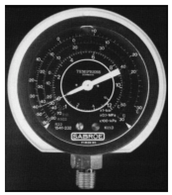
- Direct indication of the operating conditions of a compressor is by pressure gauges at suction, discharge and oil delivery. Such gauges are mounted on or near the compressor.
- Since the pressure losses along the discharge and suction lines are comparatively small on most systems, these pressures will also approximate to the conditions in the condenser and evaporator, and the equivalent saturation temperatures will be the condensing and evaporating temperatures. To indicate these temperatures for the common refrigerants, pressure gauges have further calibrations showing these equivalent temperatures.
- A pressure gauge fitted at the oil pump outlet connection will show the sum of two pressures — that generated by the pump itself plus the crankcase pressure. True oil pump pressure can only be indicated by a dual gauge, in which the oil pump discharge rotates a circular inner scale. On this gauge, the suction pressure is read off the perimeter scale and the oil pump pressure by observing the position of the needle relative to the inner disc scale.
- Gauge mechanisms are mostly of the bourdon tube type, having a flattened tube element which distorts under pressure change.
- Gas pulsations from the compressor will be transmitted along the short connecting pipes and may lead to early failure of the needle mechanism. These can be damped by restricting the tube with a valve or orifice, or oil filling the gauge, or both. Gauge needles should not be allowed to flicker noticeably from gas pulsations.
- Miniature pre-set pressure transducers are now made as components of an integrated control circuit.
In the running log, record the TRUE oil pressure (i.e. oil gauge minus suction).
5. Thermostats and Humidistats
5.1 Thermostats
Since the purpose of a refrigeration or air-conditioning system will be to reduce or maintain temperature, a thermostat will usually be fitted to stop the equipment or reduce its capacity when the required condition is reached. Types in use:
| Type | Principle | Output |
|---|---|---|
| 1 | Movement of a bimetallic element | Mechanical — direct switch or pneumatic |
| 2 | Expansion of a fluid | Mechanical |
| 3 | Vapour pressure of a volatile fluid | Mechanical |
| 4 | Electric resistance | Electric signal, must be measured and amplified |
| 5 | Electronic — various | Electric signal |
5.2 Humidistats
Where the equipment is required to maintain a predetermined level of humidity, a humidistat may be used instead of, or in addition to, a thermostat. The function will normally be to operate an electrical switch.
- Mechanical humidistats employ materials which change dimension with humidity, such as animal hair, plastics, cellulosics. These can work a switch directly.
- Electronic humidistats generally depend on the properties of a hygroscopic salt. The signal has to be measured and amplified.
6. Solenoid Valves
Electrically operated shut-off valves are required for refrigerant and other circuits. These take the form of a plunger operated by a solenoid and working directly on the valve orifice or through a servo. The usual arrangement is to energize the solenoid to open the valve and de-energize to close. Sizes up to 50 mm bore tube connections are made. Beyond this, the solenoid acts as a pilot to a main servo.
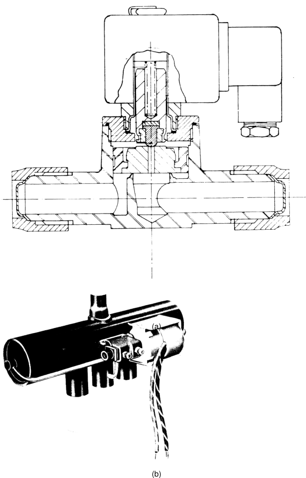
Solenoid valves are used in refrigeration and air-conditioning systems for:
- refrigerant lines,
- oil pressure pipes (to control oil return and capacity reducers),
- water and compressed air lines.
Four-port changeover valves are used to reverse flow in defrosting and heat pump circuits.
Safety characteristic: a de-energized expansion valve will act as a solenoid valve, and a de-energized solenoid valve is closed — which is why loss of power causes the valve to shut.
6.1 Room solenoids
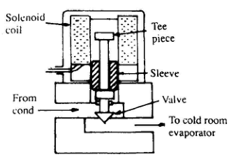
The solenoid valve is opened when the sleeve, moving upwards due to the magnetic coil, hits the tee piece and taps the valve open. It closes when the coil is de-energized and the sleeve drops and taps it shut. Loss of power therefore will cause the valve to shut, and a thermostatic switch is used to operate it through simple on/off switching.
The thermostatic switch contains a bellows which expands and contracts under the influence of fluid in a capillary and sensing bulb attached to it. The bulb is filled with freon or other fluid which expands and contracts with the temperature change of the space in which it is situated. As the temperature is brought down to the required level, contraction of the fluid deflates the bellows. The switch opens and the solenoid is de-energized and closes. Temperature rise operates the switch to energize the solenoid, which opens to allow refrigerant through to the evaporator again.
6.2 Magnetic liquid stop valve
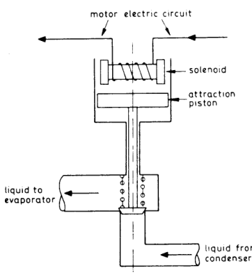
When current flows in the motor circuit the solenoid attracts up the valve and holds it open, provided the room thermostat allows the solenoid current to flow (i.e. high temperature). When the room cools the current fails and the valve shuts, and due to a time delay the compressor will pump out the room coil and so avoid liquid knock on restarting.
In multiple circuits this valve serves to cut out or cut in the particular chamber to which it is thermostatically connected. Each room has its own stop valve (thermo-electric) and thermal expansion valve as well as a hand isolating valve. The various circuits will cut out in sequence as the temperatures fall, and the coolest chamber closure will then serve to stop the machine.
7. Automatic Water Valve
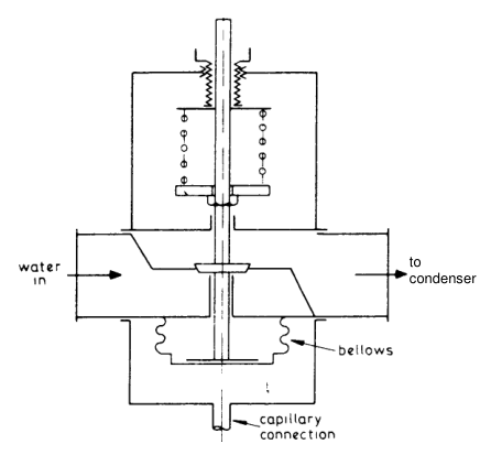
When the condenser temperature builds up the capillary bellows pressure increases and the valve opens to permit circulation. This device operates almost immediately after compressor cut-in and serves to reduce water usage. The device can easily be modified to operate a starter for fan air circulation.
8. Back Pressure Regulation Valves
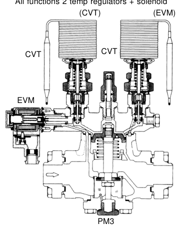
Back pressure regulation valves can be used in the suction line, and their function is to prevent the evaporator pressure falling below a predetermined or controlled value, although the compressor suction pressure may be lower.
Applications:
Construction: the simplest is spring-loaded, balancing the thrust of the spring plus atmospheric pressure on one side of a diaphragm or piston, against the inlet or evaporator pressure. For working pressures below atmospheric a helper spring is fitted below the diaphragm. Slight variations will result from changes in atmospheric pressure, but these are too small to materially affect a refrigeration control system.
- A service gauge is usually fitted adjacent to the valve or as part of the valve assembly, to facilitate setting or readjustment.
- Above about 40 mm pipe size, the basic back pressure regulation valve is used as a pilot to operate a main servo valve. Other pilot signals can be used on the same servo.
- The assembly shown has a main servo controlled by two thermostatic pilots sensing load temperature (type CVT) and a solenoid valve (type EVM). Any of these pilots may be used separately with the servo valve.
Shipboard use: the temperatures of the vegetable and dairy room are maintained at 4 °C to 5 °C by a back pressure valve fitted after the evaporator. The temperature at which the refrigerant evaporates depends on the evaporator pressure. The back pressure valve maintains the evaporator at the required pressure.
9. Other Circuit Components
9.1 Suction-to-liquid heat exchanger
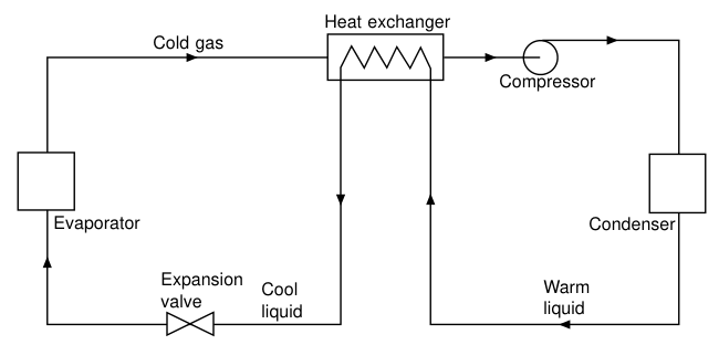
Cold gas returning from the evaporator to the compressor can be used to pre-cool the warm liquid passing from the condenser to the expansion valve. In cooling the liquid and reducing its enthalpy, a greater refrigerating effect will be obtained. This gain is offset to a greater or lesser extent by the superheating of the suction gas and the resultant reduction of mass flow into the compressor. The overall effect in terms of thermodynamic efficiency will vary with the refrigerant and the operating conditions.
Practical benefit: the suction-to-liquid heat exchanger will supply the suction superheat necessary for safe operation of a dry expansion evaporator, and the coil superheat may be less, giving more efficient use of the evaporator surface.
9.2 Condenser pressure regulators
Systems are normally designed to work satisfactorily during maximum ambient conditions, and the condenser is sized for this. In colder weather the condensing temperature and pressure will fall and the resulting lower pressure difference across a thermostatic expansion valve may lead to malfunction. A drop of pressure difference to half the normal figure may reduce mass flow below that required, and it will be necessary to prevent the condenser pressure from falling too low.
| Type of condenser | Method |
|---|---|
| Air-cooled condensers and water cooling towers | Reduce air flow by automatic dampers, fan speed control, or switching off fans where two or more drives are fitted. The control should work from pressure but can be made to work from temperature |
| Water-cooled condensers | Directly controlled water-regulating valve operated by condenser pressure, or a three-way blending valve in the water circuit |
| Any | Pressure-operated bleed valve in a bypass across the condenser, to divert hot gas to the receiver. The valve diaphragm is balanced by a pre-set spring and will open the bypass if the condensing pressure falls |
| Any | Pressure-operated valve between condenser and receiver, to restrict the flow and allow liquid to accumulate in the condenser, reducing its efficiency |
- For operating economy it is important that such valves are not set at too high a pressure.
- Towers should have thermostatic control of the fan to prevent water freezing on the packing in winter.
- An integrated control circuit with an electronic expansion valve can be arranged to permit the condensing pressure to fall, providing the valve can pass the refrigerant flow required to meet the load. This gives lower compressor energy costs.
- In all forms of condenser pressure control, the minimum maintained pressure should be the lowest which will give satisfactory operation, in the interests of running economy.
9.3 Capacity reduction injection valves
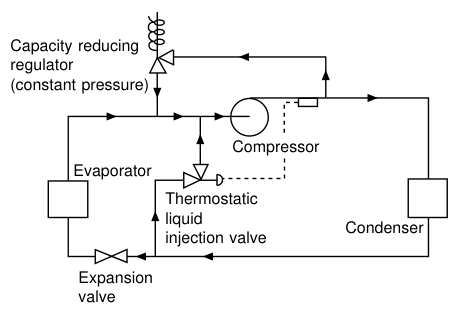
Where a compressor does not have any capacity reduction device and on–off switching will not give the degree of control required by the process, the cooling capacity can be regulated by injecting discharge gas back into the suction. It has the effect of keeping the evaporator pressure constant, regardless of load, and can have a wide range of capacity reduction, down to 10 % of full load. It is a constant pressure valve, balancing the suction pressure against a pre-set spring.
Since the suction gas to the compressor would then be hotter than its normal slightly superheated condition, the compressor may overheat and the discharge gas become too hot for correct and safe working. This form of capacity reduction is usually combined with a liquid injection valve, thermostatically operated, which introduces liquid into the suction to keep it cool. The fitting of dual interdependent controls of this sort, both of which have inherent fail-unsafe possibilities, should be approached with caution.
The safer circuit injects the discharge gas directly after the expansion valve or into the evaporator outlet and before the sensor of the expansion valve. With this arrangement the expansion valve will admit extra refrigerant and gas entering the compressor will be normally cool. These control methods are wasteful of energy.
9.4 Relief valves
Under several possible conditions of malfunction, high pressures can occur in parts of the system and mechanical relief devices are advised or mandatory. The standard form is a spring-loaded plunger valve.
- No shut-off valve is permitted between the relief valve and the vessel it protects, unless two such valves are fitted, when the shut-off may isolate one at a time.
- Two valves are required on a vessel greater than 285 litres in volume.
- In all cases the outlet of the valve must be led to the open air, in a location where the sudden discharge of refrigerant will not cause annoyance or danger.
- Under certain circumstances a relief valve from the high-pressure side may enter the low side of the same system.
- Small vessels may have a plug of a low melting point metal, which will melt and release the pressure in the event of fire.
- Plunger-type relief valves, if located outdoors, should be protected from the ingress of rain, which may corrode the seat. Steel valves, when installed, should have a little oil poured in to cover the seat as rust protection.
- To prevent overpressure within a compressor, a relief valve or bursting disc is often fitted between the inlet and discharge connections.
The shipboard bursting disc: a safety bursting disc is fitted between the compressor discharge and the suction. This may be of nickel with a thickness of 0.05 mm. A ruptured disc is indicated by suction and discharge pressures being about equal.
9.5 Shut-off valves
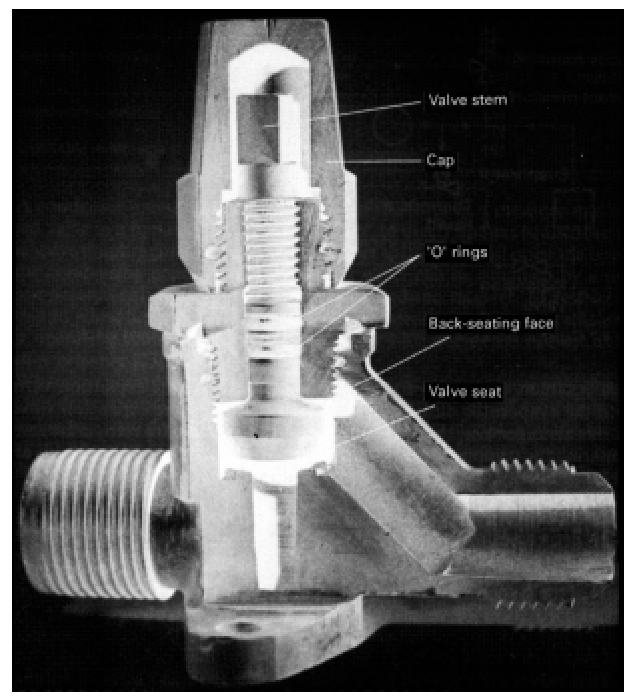
Manual stop valves are required throughout a circuit to permit isolation during partial operation, service or maintenance.
- Small valves which are to be operated frequently have a packless gland, either a diaphragm or bellows, and a handwheel.
- Valves of all sizes which are only used occasionally will be sealed with "O" rings. As a safeguard against leakage, they have no handwheel fitted and the stem is provided with a covering cap which is only removed when the valve is to be operated. The stem will have flats for operation by a spanner. Most such valves can be back-seated to permit changing the "O" rings.
- Valves should not be installed with the stem downwards, as any internal dirt will fall into the spindle thread.
- Under low-temperature conditions, ice will form on the spindle and will be forced into the gland if the valve is operated quickly. Under such circumstances the spindle should be well greased, or the ice melted off first.
- Service stop valves on small compressors may also carry a connection for a pressure cut-out or gauge, or for the temporary fitting of gauges or charging lines when servicing. The valve back-seats to close off this port while gauges are being fitted.
- Valve seats are commonly of soft metal or of a resistant plastic such as PTFE.
9.6 Strainers
Piping circuits will usually contain a small quantity of dirt, scale and swarf, no matter what care is taken to keep these out.
- A strainer is fitted in the compressor suction to trap such particles before they can enter the machine. Such strainers are of metal mesh and will be located where they can be removed for cleaning. In some configurations two strainers may be fitted.
- As an extra safeguard, on new compressors a fabric liner may be fitted inside the mesh strainer to catch fine dirt. Such liners must be removed at the end of the running-in period, as they create a high resistance to gas flow.
- Oil strainers may be of metal mesh and within the sump, in which case the sump must be opened for cleaning. Self-cleaning disc strainers are also used, the dirt falling into a drain pot or into the sump itself.
- There is an increasing tendency to provide replaceable fabric oil filters external to the compressor body, following automobile practice.
9.7 Strainer-driers
With the halocarbons it is essential to reduce the water content of the refrigerant circuit to a minimum by careful drying of components and the fitting of drying agents in the system.
- The common form of drier is a capsule charged with a solid desiccant such as silica gel, activated alumina or zeolite (molecular sieve), and located in the liquid line ahead of the expansion valve.
- These capsules must have strainers to prevent loss of the drying agent into the circuit, and so form an effective strainer-drier to also protect the valve orifice from damage by fine debris.
- Large driers are made so they can be opened, and the spent drying agent removed and replaced with new. Small sizes are throwaway. Driers may also be used in the suction line.
If the liquid line leaving the drier or strainer (if separate) is colder than the inlet, there is a severe pressure drop within, indicating dirt. A new drier, or cleaning of the strainer, will cure this.
9.8 Sight glasses
Pipeline sight glasses can be used to indicate whether gas is present in a pipe which should be carrying only liquid. The main application in refrigeration is in the liquid line from the receiver to the expansion valve. If the equipment is running correctly, only liquid will be present, and any gas bubbles seen will indicate a refrigerant shortage.
- Sight glasses for the halocarbons are commonly made of brass, and may have solder or flare connections. For ammonia they are made of steel or cast iron.
- Since the interior of the system can be seen at this point, advantage is taken in most types to insert a moisture-sensitive chemical which will indicate an excess of water by a change of colour. When such an indication is seen, the drier needs changing or recharging, and the colour should then revert to the "dry" shade.
- Sight glasses for liquid observation are commonly fitted at various points in the domestic type systems.
Moisture in halocarbon circuits will be indicated by the colour trace on the sight glass. Immediate action is required, especially with a hermetic or semi-hermetic compressor, before damage is caused. The drier should be changed and the sight glass watched for reversal of the colour to "dry". Bad cases of contamination may need a second change of drier.
9.9 Charging connection
In order to admit the initial refrigerant charge into the circuit, or add further if required, a charging connection is required. The safest place to introduce refrigerant will be ahead of the expansion valve, which can then control the flow and prevent liquid reaching the compressor. The usual position is in a branch of the liquid line, and it is fitted with a shut-off valve and a suitable connector with a sealing cap or flange. A valve is needed in the main liquid line, just upstream from the branch and within reach.
9.10 Non-return (check) valves
Non-return or check valves will be found in the following positions:
9.11 Liquid refrigerant pumps
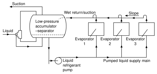
In a flooded evaporator the movement of the liquid may be sluggish, with resulting low heat transfer. Liquid pumps can be used to circulate refrigerant from the suction separator (or "surge drum"), through the evaporator(s) and back. In the separator, remaining liquid falls back and is recirculated, while vapour goes to the compressor. These pumps are found mainly on low-temperature coldrooms, blast freezers and process applications.
9.12 Suction separators and accumulators
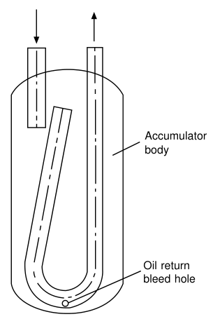
Suction line accumulators are sometimes inserted in halocarbon circuits, to serve the purpose of separating return liquid and preventing it passing over to the compressor. Since this liquid will be carrying oil, and this oil must be returned to the compressor, the outlet pipe within the separator dips to the bottom of the vessel and has a small bleed hole, to suck the oil out.
Suction traps are now widely used, particularly on rolling piston and scroll compressors, to prevent liquid passing into the compressor.
Liquid separators: separation vessels can be inserted in a liquid line. Liquid will fall to the bottom and pass through an expansion device to an evaporator. High-pressure gas will rise to the top of the vessel and can then be used for heating or for hot gas defrost of another heat exchanger.
9.13 Overheat protection
Small compressors will have motor overheat protection adjacent to the hermetic shell or built into the winding, and larger motors will have contactor-starters with overcurrent devices. Overheat protection is also fitted on many machines to guard against high motor winding, cylinder head or oil temperatures. These usually take the form of thermistor detectors, connected to stop the motor.
10. Integrated Control Systems
The purpose of the various electromechanical elements of a circuit is to effect monitoring, safety and automatic control, and these may be connected separately into a custom-built system. The availability of electronic logic circuits gives the possibility of integrated systems and superior control, using a large number of input signals.
Observed parameters: electrical supply, load temperature, air and water flows, number of compressors running and loading stages, condenser pressure, number of condensers running, condenser fan speed, evaporator temperature, discharge temperature, cylinder head temperature, motor current, expansion valve opening, refrigerant shortage.
Control may then be effected of: number and stages of compressors running, limitation of motor start frequency, limitation of maximum electrical demand, number of fans or condensers running, fan speeds, number of fans or evaporators running, warning of faulty plant, shutting down faulty plant, starting standby plant, monitoring energy used, printed running logs, scheduling maintenance, remote alarm systems.
Integrated control systems are mainly found on factory-assembled equipment, but the increased use of programmable logic controllers for process control is giving designers and installation mechanics the experience to apply these methods to custom-built refrigeration systems.