
Refrigerants
On a ship the refrigerant is both the working fluid and the main hazard.
Key Principles at a Glance 5 points
- Every refrigerant is a compromise — no single fluid meets all ten requirements, so each selection is a judgement that must be recorded in the plant data sheet.
- The refrigerant fixes four things: the pressure range, the materials, the oil, and the safety precautions. Change the fluid and you change all four.
- R12 draws air into the system through any leak, because its evaporator-side pressure falls below atmospheric at low temperature. R22 avoids this and is why it replaced R12.
- Never top up a leaking circuit without repairing the leak first — the only exception being a continuous process plant where a shutdown costs more than a small continuous leak.
- In TEWI, the energy-consumption term usually dominates leakage. Condenser cleanliness and correct expansion-valve setting are environmental measures, not just efficiency measures.
1. What the Engineer Must Understand
Never top up a leaking circuit without repairing the leak first — the single exception being a continuous process plant where the cost of a shutdown overrides the cost and inherent danger of a small continuous leak. Never release refrigerant to atmosphere. Always work to the maker's data sheet and the SMS.
- Every refrigerant is a compromise. There is no perfect refrigerant for all operating conditions; the fluids in general use are selected as being nearest to the ideal.
- The refrigerant fixes the pressure range, the materials, the oil and the safety precautions.
- The pressure/temperature relationship is the whole game. Once you know the refrigerant, a gauge reading tells you a temperature, and vice versa. That is what makes fault-finding possible.
- Environmental regulation has rewritten the list. R11, R12, R114, R502 and R13B1 have all ceased production in Montreal Protocol signatory countries. R22 is a transitional HCFC being phased out. Ammonia is the only pre-1987 fluid still considered environmentally friendly — but it is not readily suited to commercial or air-conditioning work because of toxicity, flammability and attack on copper.
2. Requirements of a Refrigerant
Ten requirements for a fluid used as a refrigerant:
A high latent heat of vaporisation
A high density of suction gas
Non-corrosive, non-toxic and non-flammable
Critical temperature and triple point outside the working range
Compatibility with component materials and with lubricating oil
Reasonable working pressures — not too high, and preferably not below atmospheric pressure
High dielectric strength (for compressors with integral electric motors)
Low cost
Ease of leak detection
Environmentally friendly
No single fluid has all of these. Each selection is therefore a judgement, and the judgement must be recorded in the plant data sheet.
3. The Fluids Used on Ships — One by One
R 12 — dichlorodifluoromethane (CCl₂F₂)
- Halogenated hydrocarbon derived from methane (CH₄) with hydrogen displaced by chlorine and fluoride.
- For cargo installations R 12 replaced carbon dioxide and is in turn being replaced by R 22.
- Non-toxic except in high concentrations producing oxygen deficiency.
- Decomposes in contact with flame to give pungent and poisonous products — chlorine (Cl₂) and phosgene (COCl₂).
- Gas escaping under pressure will cause skin damage on contact.
- Odourless, non-irritant, not considered flammable or explosive.
- Working pressures and temperatures are moderate; the high critical temperature (112 °C) is well above the working range.
- Critical pressure 40 bar; discharge pressure 7.4 bar; suction pressure 1.8 bar.
With R 12 the evaporator-side pressure falls below atmospheric at low temperatures, so air can be drawn into the system through any leak — this is a major consideration and a common cause of "air in the system".
R 22 — chlorodifluoromethane (CHClF₂)
- Popularity as a refrigerant for cargo installations increased at the expense of R 12.
- More suitable for a lower temperature range than R 12, because the pressure on the evaporator side of the system is higher than atmospheric at low temperatures — thus reducing the risk of drawing air into the system.
- Performance is better, approaching that of ammonia.
- Chemical and other properties similar to R 12 except that it is not miscible with oil over the full temperature range (miscible in the condenser; in the cold evaporator there are two liquid layers, the top mostly oil and the bottom mostly refrigerant).
- Discharge pressure 12.0 bar; suction pressure 3.0 bar; refrigerating capacity 571 J/s.
- It is an HCFC — ODP 0.05, GWP 1700 — and is now regarded as a transitional refrigerant, being phased out of production under the Montreal Protocol.
R 11 — monofluorotrichloromethane (CCl₃F)
Found suitable for air conditioning installations. A CFC with a high ODP, now phased out.
R 502
Composed of 48.8 % R 22 and 51.2 % R 115 (C₂ClF₅). Particularly suited for use with hermetic compressors. A CFC (because of the R 115 component), now phased out.
R 134a — the long-term R 12 replacement
Chlorine-free HFC. ODP 0, GWP 1300. Fully miscible with oil at both 0 °C and 35 °C (specific mass 1295 kg/m³). It is the reference fluid for the TEWI worked example.
Carbon dioxide (CO₂)
- Working pressures are high — about 70 bar at the compressor discharge and 20 bar at the suction. The machinery and system must therefore be of substantial construction.
- Critical temperature is low (31 °C), which causes problems in areas with high sea water temperature, and it has a low coefficient of performance.
- The gas is not explosive or flammable, but a leak is potentially dangerous because it can displace air and asphyxiate.
- Liquid is stored in steel bottles at high pressure, ideally in a cool space. Temperature rise causes pressure rise, relieved by rupturing of a safety disc and release of the gas.
- Non-miscible with oil at all temperatures (specific mass 596 kg/m³), so oil drainage pots are essential — but as the critical temperature is only 31 °C and once the sea temperature reaches about 23 °C the critical point is reached, the plant efficiency steadily decreases from that point.
Ammonia — R 717
- Thermodynamically, ammonia is a good refrigerant, but it is explosive, poisonous and an irritant. The explosive mixture is 16 to 25 per cent in air.
- Corrosive to copper and its alloys, so ferrous materials are used for components in an ammonia system. All jointing must be lead or soft iron, with steel tubing.
- Highly soluble in water, with which it forms ammonium hydroxide, a weak base. About 1300 volumes of ammonia can be dissolved in 1 volume of water at low temperature, but it is easily expelled by boiling — this action makes the vapour absorption refrigerator possible.
- Because of this high solubility, a wet cloth held to the face gives some protection against an ammonia leak in an emergency — although a breathing apparatus would normally be worn.
- Because of the hazards, ammonia is used mainly ashore and on fishing vessels.
- Discharge pressure 11.7 bar; suction pressure 2.4 bar; critical pressure 113.7 bar; critical temperature 133 °C. Specific enthalpy of vaporisation at −15 °C is 1314.2 kJ/kg — vastly higher than any Freon, which is why so little ammonia circulates for a given duty.
- ODP 0, GWP 0.
Ammonia systems have continuous oil migration and require attention every week — in some cases every day — to ensure maximum working efficiency.
Halogen-free long-term alternatives
| Refrigerant | ODP | GWP | Substitute for |
|---|---|---|---|
| R717 ammonia | 0 | 0 | R22, R502 |
| R600a isobutane | 0 | 3 | R114 |
| R290 propane | 0 | 3 | R12, R22, R502 |
| R1270 propylene | 0 | 3 | R12, R22, R502 |
Note the trade-off: the hydrocarbons have negligible GWP and ODP but are highly flammable. They appear in domestic and small commercial equipment ashore; they are not a marine cargo-installation solution.
4. Property Table — the Numbers an Oral May Ask For
| Property | CCl₂F₂ (R12) | CO₂ | NH₃ (R717) |
|---|---|---|---|
| Discharge pressure, bar | 7.4 | 72 | 11.7 |
| Suction pressure, bar | 1.8 | 23 | 2.4 |
| Critical pressure, bar | 40 | 73.8 | 113.7 |
| Critical temperature, °C | 112 | 31 | 133 |
| Spec. enthalpy of liquid, kJ/kg at −15 °C | 22.3 | 48.9 | 112.4 |
| Spec. enthalpy of vaporisation, kJ/kg at −15 °C | 158.7 | 274.7 | 1314.2 |
| Spec. enthalpy of vapour, kJ/kg at −15 °C | 181.0 | 323.6 | 1426.6 |
| Spec. enthalpy of liquid, kJ/kg at 30 °C | 64.6 | 193.8 | 323.1 |
| Spec. enthalpy of vaporisation, kJ/kg at 30 °C | 135.0 | 63.1 | 1145.8 |
| Spec. enthalpy of vapour, kJ/kg at 30 °C | 199.6 | 266.9 | 1468.9 |
| Spec. volume of liquid, m³/kg | 0.0007 | 0.001 | 0.0015 |
Freon comparison:
| Property | Freon 12 | Freon 22 | Freon 502 |
|---|---|---|---|
| Chemical formula | CCl₂F₂ | CHClF₂ | CHClF₂ / CClF₂CF₃ |
| Discharge pressure, bar | 7.4 | 12.0 | 13.1 |
| Suction pressure, bar | 1.8 | 3.0 | 3.5 |
| Refrigerating capacity, J/s | 318 | 571 | 561 |
5. Environmental Regulation — the Part That Changes What You Are Allowed to Do
Ozone depletion potential (ODP)
The ozone layer in the upper atmosphere filters ultraviolet radiation. Research found the layer thinning due to emissions of chlorofluorocarbons (CFCs), halons and bromides. The Montreal Protocol (1987) agreed that production of these chemicals would be phased out by 1995 and alternatives developed.
- CFCs used as refrigerants: R11, R12, R114, R502 — all ceased production in signatory countries.
- R13B1 is a halon — also ceased.
- R22 is an HCFC and is regarded as transitional, to be completely phased out of production by 2030 under the Montreal Protocol.
European Community dates set out in the source:
| Date | Restriction |
|---|---|
| 1/1/2000 | CFCs banned for servicing existing plants |
| 1/1/2000 | HCFCs banned for new systems with shaft input power greater than 150 kW |
| 1/1/2001 | HCFCs banned in all new systems except heat pumps and reversible systems |
| 1/1/2004 | HCFCs banned for all systems |
| 1/1/2008 | Virgin HCFCs banned for plant servicing |
Prior to 1987 total CFC emissions were made up from aerosol sprays, solvents and foam insulation; refrigerant emissions were only about 10 % of the total. Nevertheless all users have replaced CFCs with alternatives.
Global warming potential (GWP)
GWP is quoted relative to CO₂ = 1.0. Emission of 1 kg of R134a is equivalent to 1300 kg of CO₂.
| Refrigerant | Type | ODP (R11 = 1.0) | GWP (CO₂ = 1.0) |
|---|---|---|---|
| R22 | HCFC | 0.05 | 1700 |
| R134a | HFC | 0 | 1300 |
| R404a | HFC | 0 | 3750 |
| R407c | HFC | 0 | 1610 |
| R410a | HFC | 0 | 1890 |
| R411b | HCFC | 0.045 | 1602 |
| R717 ammonia | — | 0 | 0 |
| R290 propane | — | 0 | 3 |
| R600a isobutane | — | 0 | 3 |
| R1270 propylene | — | 0 | 3 |
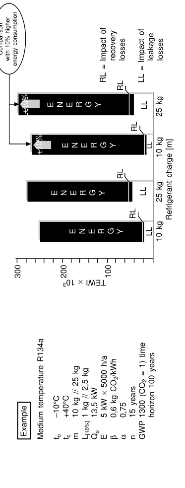
Total equivalent warming impact (TEWI)
The choice of refrigerant affects the GWP of the plant, but other factors also contribute to the overall global warming impact, and this is represented by TEWI. It includes:
- refrigerant leakage,
- refrigerant recovery losses, and
- energy consumption.
TEWI is a term which should be calculated for each refrigeration plant.
TEWI formula:
| Term | Component |
|---|---|
| (GWP × L × n) | Direct |
| (GWP × m [1 − arecovery]) | Recovery losses |
| (n × Eannual × b) | Indirect (energy) |
Symbols:
| Symbol | Meaning |
|---|---|
| GWP | global warming potential (CO₂-related) |
| L | leakage rate per year [kg] |
| n | system operating time [years] |
| m | refrigerant charge [kg] |
| arecovery | recycling factor |
| Eannual | energy consumption per year [kWh] |
| b | CO₂ emission per kWh (energy mix) |
The energy-consumption term usually dominates. That is why condenser cleanliness, correct expansion-valve setting and control of condensing pressure matter as much for "environmental" performance as leakage does.
6. Handling, Charging and Leak Detection
Charging
Normally charging is made through the liquid charging valve at the high-pressure side. The safest place to introduce refrigerant is ahead of the expansion valve, which can then control the flow and prevent liquid reaching the compressor. The usual position is a branch of the liquid line, fitted with a shut-off valve and a suitable connector with sealing cap or flange. A valve is needed in the main liquid line just upstream from the branch and within reach.
Shipboard charging sequence:
Put the drier in the system — open the inlet and outlet drier valves, shut the bypass valve.
Weigh the refrigerant cylinder before and after charging to ascertain the quantity charged.
Collect the gas by shutting the receiver outlet. The compressor will cut off on LP trip. Check the liquid level in the sight glass.
Connect the charging pipe to the cylinder. Keep the cylinder vertical. Use the liquid valve on the cylinder.
Connect the charging pipe to the liquid side of the system and crack open the cylinder valve — this purges entrapped air. Tighten the charging connection.
Open the charging valve and the cylinder liquid valve; liquid refrigerant flows in.
Start the compressor on "manual" and continue to charge. Observe the liquid level in the sight glass.
Close the charging valve and pump down the entire charge until suction pressure is just above zero.
Stop the compressor and close the discharge valve.
Keep cooling water running for some hours.
Purge air out through the purging valve on the condenser until refrigerant gas appears at the valve.
Close the cylinder liquid valve.
Close the drier inlet and outlet valves and open the bypass valve.
Start the system by opening the receiver outlet valve; observe efficiency for 20 minutes; check the liquid level in the receiver.
If additional charging is required, repeat the procedure.
Calculate the amount of refrigerant charged and enter it in the engine log book.
Reed's gives the same instruction more briefly: the freon cylinder is connected loosely to the filling valve on the regulator outlet; the bottle valve is cracked open to clear air from the connecting pipe, and the nut tightened. The bottle must be kept upright to prevent entry of liquid when the connection is made to the suction side. Charging is continued until the bubbles disappear from the sight glass.
The condenser gauge should read about 7 °C above the sea water inlet and the suction gauge about 7 °C below the evaporator on the equivalent saturation temperatures for the pressures.
Leak detection
For freon systems a leak detector lamp burning methylated spirits or bottled gas can be used. The lamp has a pale blue or colourless flame which turns green when freon is drawn into it by a sampling tube. The open end of the tube is held close to joints and other potential leakage points around the pipework. The mechanical seal on the shaft is always tested, because freon from the crankcase may be lost through wear or a fault. A large leak will cause the flame to burn violet, and it is sometimes necessary to ventilate the space to clear excess gas before the leak can be pinpointed. If no lamp is available, escaping refrigerant can be detected by brushing soapy water over joints and flanges — bubbles indicate the leak.
Staff should be forbidden to smoke while leak testing or repairing — many operatives are ignorant of the danger to their health from smoking in the presence of traces of halocarbons (the flame decomposes them to phosgene and chlorine). A regular leak test should be part of the general maintenance schedule.
Where gas is detected at the shaft gland of an open compressor which is not turning, run the compressor for a short time to re-lubricate the gland — the leak may then cease.
Leakage rectification
Permanent solution: renew the whole section of copper pipe. Temporary, if time is short:
Pump down the refrigerant into the condenser.
Use a ferrule connection to seal the leak. Cut the copper pipe with a pipe cutter.
Insert ferrule female and female pieces.
Use thread seal tape on the threads. Tighten.
Open the refrigerant valves and confirm the leakage has stopped.
Note: cold repairs are possible using superfast drying plastic steel putty solutions or certain acrylic solutions — but cold repair is preferred only to arrest the leakage temporarily and for a short period only.
7. Safety Points That Must Not Be Forgotten
- Never release refrigerant to atmosphere.
- Liquid refrigerant causes frostbite — wear gloves and goggles when handling charging lines.
- Freon decomposes in flame to chlorine and phosgene — never smoke or use a naked flame near a leak or an open circuit.
- CO₂ leaks asphyxiate by displacing air.
- Ammonia is explosive between 16 and 25 % in air, poisonous and an irritant; a wet cloth to the face gives some protection in an emergency but breathing apparatus is the correct answer.
- Do not add refrigerant to a leaking circuit without first making a repair.
- Suspect oil (from a hermetic or semi-hermetic motor failure) can contain halogen acids — detect by acrid smell or litmus paper. Eye goggles and rubber gloves should be worn when handling such suspect oil. If shown to be acid, the oil must be removed and carefully disposed of and the system thoroughly cleaned out.