
System Operation, Watchkeeping and Shipboard Procedures
Automatic plant still needs a watchkeeper — the log sheet is what turns a running machine into a monitored one.
Key Principles at a Glance 8 points
- Automation does not remove the duty of understanding: if the plant is not monitored it may run abnormally for some time before a fault is noticed, by which time considerable damage may have occurred.
- The two cardinal rules: the discharge pressure should correspond to a condensing temperature about 7–8 °C above the sea water inlet, and the suction gauge to an evaporating temperature about 7 °C below the evaporator.
- The log must record true oil pressure (oil minus suction), not just the oil gauge reading — a single oil gauge number tells you nothing on its own.
- Safe isolation is a sequence, and the order matters: pump down first, then isolate electrically, then isolate valves, then display the warning board.
- Air in the system shows as a steady rise in the high-pressure gauge; it stratifies on top of the liquid in the condenser because it will not condense.
- Brine should be kept alkaline and checked with litmus or phenolphthalein, with density taken by hydrometer at 15.5 °C — normally 1250 kg/m³ and pH 8.5 is satisfactory.
- A suction valve test that develops 0.4 bar of vacuum or more proves the suction valves are holding; close the suction valve slowly or the oil in the crankcase will foam.
- Fans must never run without filters in place, or dirt will be deposited in inaccessible parts of the plant.
1. What the Engineer Must Understand
The maker's manual, the SMS and the class rules override. No refrigerant is allowed to be released to atmosphere. All work on the refrigerant circuit is permit-controlled.
- A large proportion of refrigerating and air-conditioning equipment is now fully automatic in operation, but that does not absolve the user from the responsibility of understanding how it operates and being able to observe this operation. If this is not done, the plant may run abnormally for some time before a fault is noticed, by which time considerable damage may have occurred.
- The initial requirement is for the equipment to be fitted with sufficient pressure gauges and other monitoring devices to indicate the conditions under which it is working. It is helpful to mark these with the normal working limits when commissioning the plant.
- Persons operating the plant should understand the meaning of any indicator or warning lights fitted to the control panels. It is important that the operator should be aware of the temperature gradients to be expected with the system, so as to be able to compare actual working conditions with the design figures. Any changes should be interpreted as changes of ambient or load. A running log should be kept, as far as possible, to monitor working conditions.
- Where the switching of plant is purely manual, the plant instructions should specify the limits of control, and not leave these to the shift operator, who may not be sufficiently skilled to take the correct decisions.
- Standby plant is often fitted, and it is part of the operation discipline to change over machines to ensure that they get even wear and keep all sets in running order. All operation staff should be aware of the method of bringing standby plant into use in an emergency.
- Where refrigerant valves need to be opened or closed as part of plant operation, this should be carried out only by competent and responsible staff.
2. Normal Running Readings
2.1 The two cardinal rules
Both are given by McGeorge, and both are used constantly in fault-finding:
The compressor discharge pressure gauge should show a pressure with an equivalent condensing temperature about 7 or 8 °C above the sea water inlet.
The suction gauge should show an equivalent evaporating temperature about the same amount (about 7 °C) below the evaporator.
These two relationships are the quickest sanity check available on any Freon plant. If the condensing temperature is much more than 7–8 °C above sea water inlet, the condenser is dirty, air-locked, or the cooling water flow is restricted. If the evaporating temperature is far below the load temperature, the coil is starved or frosted, or the load is too great.
2.2 Pressure gauge conventions
The pressure gauge on the compressor discharge shows the gas pressure and also has marked on it the relative condensing temperature. This is not the actual temperature of the gas, which is higher and shown by the thermometer.
Similarly, since the pressure losses along the discharge and suction lines are comparatively small, the compressor suction and discharge pressures approximate to the conditions in the evaporator and condenser, and the equivalent saturation temperatures will be the evaporating and condensing temperatures. To indicate these temperatures for the common refrigerants, pressure gauges have further calibrations showing these equivalent temperatures.
2.3 Shipboard evaporating temperatures (DE plant)
The temperatures of the vegetable and dairy rooms are maintained at 4 °C to 5 °C by a back pressure valve fitted after the evaporator. The temperature at which the refrigerant evaporates depends on the evaporator pressure. The back pressure valve maintains the evaporator at the required pressure.
2.4 The running log
The detection of abnormal operation can only occur if normal operation is monitored. Since refrigeration is a thermal cycle, the obvious readings to be taken will be temperature and the related refrigerant pressure.
The skilled operator or the visiting service mechanic will have a working knowledge of the pressures and temperatures to be expected, but will not be able to make an accurate assessment of the actual conditions without plant measurements for comparison. The commissioning log will show readings taken at that time, but only at one set of running conditions.
It is therefore essential on a plant of any size to maintain some kind of running record, so that performance can be monitored with a view to detecting inefficiency and incipient troubles. The degree of complexity of this running log must be a matter of judgement, and a small amount of useful information is to be preferred to a mass of data which would be confusing.
The basic columns:
These, together with space for comments, date and time, form the log sheet:
| Time | S | D | OG | Oil temp | S temp | D temp | Brine in | Brine out | Amb P | Amb DB | Amb WB | Amps |
|---|---|---|---|---|---|---|---|---|---|---|---|---|
| 08.00 | 2.8 | 10 | 4.7 | 1.9 | −8 | 27 | +4 | −1 | 3.1 | 11 | 9 | 190 |
| 10.00 | 2.1 | 10.5 | 3.9 | 1.8 | −14 | 29 | −3 | −8 | 3.1 | 15 | 12 | 175 |
| 12.00 | 2.1 | 10.5 | 3.9 | 1.8 | −14 | 29 | −2 | −7.5 | 3.1 | 19 | 13 | 175 |
| 14.00 | 2.1 | 11 | 3.9 | 1.8 | −14 | 30 | −3 | −8 | 3.1 | 20 | 14 | 170 |
Key: S = suction, D = discharge, OG = oil gauge, P = pump, DB = dry bulb, WB = wet bulb.
Shipboard requirement: the refrigeration plant parameters monitored and recorded indicate the performance of the plant.
3. Shipboard Plant Operation
3.1 The DE refrigerating plant — normal running
- The refrigeration plant runs continuously to maintain the cold room temperatures.
- The compressor cuts in and cuts out automatically, depending on the room temperatures.
- Two plants of the same refrigerating capacity are provided, so that one plant will be available during the maintenance of the other plant.
- Temperatures of cold rooms are to be monitored periodically.
- A timer defrosts the evaporator coils located in the cold rooms automatically, at the preset intervals.
- The refrigeration plant parameters monitored and recorded indicate the performance of the plant.
- The thermostats located in the rooms control the opening and closing of the solenoid valve according to the required temperatures.
- As the temperature of each room reaches the set value, its solenoid stops the flow of the liquid refrigerant to that room.
3.2 The automatic Freon system — normal cycle
The operational summary:
Compressor start/stop by the LP controller on suction pressure. HP cut-out (hand reset) for high discharge pressure. Room thermostats open and close compartment solenoids. When all solenoids shut, suction pressure falls and the LP controller stops the machine. As rooms warm, solenoids re-open, suction pressure rises and the LP controller restarts the machine. Each room has its own TEV. A master solenoid on large systems closes on a fault to prevent flooding.
4. Cargo Refrigeration Systems
4.1 Brine circuits — properties of brine
It is an advantage if the coolant coil through the cold chamber contains a fluid which is virtually non-harmful to the contents of the space in the event of leakage.
Small domestic units circulate the coil with the refrigerant (direct expansion), but larger cargo units usually employ an evaporator and a loop of circulation through the evaporator to the cold chambers and back, which contains brine. The big advantages are:
- the brine pipes have a much larger reserve of cold than refrigerant coils when the plant is stopped;
- various circuits can easily be arranged — e.g. cooling, chilling, defrosting.
Composition and management:
- The brine as used is a mixture of distilled water (preferably) and calcium chloride (CaCl₂).
- The colder the brine circuit, the more dense the brine in circulation has to be, to avoid any freeze-up.
- Under certain conditions sodium chloride (NaCl) could be used with water, but an alkali such as caustic soda (NaOH) would be required as an addition, at about 1 % of the solution.
- The brine should be maintained in an alkaline state under all conditions; this can easily be checked by the use of litmus paper, phenolphthalein, etc.
- Brine density should also be taken regularly by standard hydrometer test at 15.5 °C, and a regular check should also be taken for brine leakage at the brine header tank, which serves to keep a head on the system.
- There is a possibility that the air content of brine rooms could become explosive or inflammable under conditions of hydrogen gas liberation due to corrosive action; it is advisable not to allow naked lights.
The brine circuit consists of a brine room containing distribution headers, mixing tanks, evaporators, pumps, etc., then the various piping systems to cold storage spaces. The piping is usually tested to 7 bar, or 2.5 × working pressure, whichever is the greater; pipes commonly of mild steel externally galvanised and painted, about 40 mm bore. It is usual to regulate the flow of brine by the return valves on the distribution and return headers.
Brine density and freezing point table:
| Freezing point (°C) | Density at 15.5 °C (kg/m³) |
|---|---|
| −3 | 1050 |
| −7 | 1100 |
| −13 | 1150 |
| −21 | 1200 |
| −32 | 1250 |
| −46 | 1290 |
Normally 1250 kg/m³ density would be satisfactory for most brine circulation, with a pH value of 8.5. Non-freezing solutions can also be based on organic fluids; ethylene and propylene glycol are in general use.
4.2 Coil surface ratios
- For chilling chambers, about 3 m³ of chamber would require about 1 m² of pipe cooling surface, increased to 4.5 m³ if air is circulated.
- For freezing chambers the ratio is about 1.5 m³/m² (2.2 m³/m² air circulated).
- A direct expansion coil would be approximately 120 m² of surface area per kg of ice per second.
4.3 Battery system
This system is to blow air across a brine or direct expansion grid and circulate the storage space. It is well suited to higher temperature storage, e.g. shellac, as there is no dripping from overhead grids on to the cargo. Also this system gives some control over the humidity, as moisture will be deposited on the cooling coil.
- The supply of air circulation to any storage room will reduce the brine cooling surface required by as much as 50 %.
- Direct expansion grids employ only about 40 % of brine-cooled grid pipe surface, but do not have the same large reserve of cold.
4.4 Ice making
- The ice tank is usually wrought iron and contains lead-coated sheet steel ice moulds.
- The moulds are immersed in a brine bath, and a cooling coil (brine or refrigerant) lowers the bath temperature until the water in the moulds is converted to ice.
- The tank is insulated and coil supply and return valves are fitted.
4.5 Hold ventilation control
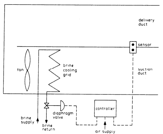
- The sensor bulb is situated in a bypass pocket in the air trunk and senses air delivery temperature whether fans operate normally or reversed.
- The diaphragm-operated control valve can be supplied as direct acting (fail in the open position) or reverse acting (fail in the shut position).
- For fruit cargo where frost damage could occur, reverse acting valves which would fail in the shut position on air failure are used.
- For chilled meat cargo where failure would mean a long period of time would pass before the temperatures could be again reduced to the correct value, direct acting valves are preferred.
This fail-safe choice is an excellent oral point: the fail direction is chosen by asking which failure does the cargo survive better — frost damage, or a slow rise in temperature.
4.6 Refrigerated containers
Refrigerated containers may each have their own refrigerator, or the containers may be connected to the ship's ducts.
5. Safe Isolation of the System
The full shipboard isolation sequence:
Note the discipline: pump down first, then isolate electrically, then isolate valves, then display the warning board. The order matters — pumping down before electrical isolation means the compressor is not required to run after the permit is issued.
6. Purging Air from the System
6.1 The symptom and the mechanism
The symptom which indicates air in the system is a steady increase in the high-pressure gauge reading. Accumulation of air reduces the effective area of condenser available for condensing refrigerant.
McGeorge's statement: this is indicated by an abnormally high condenser pressure gauge reading and possibly by the presence of small bubbles in the sight glass.
6.2 The test for air in the condenser
6.3 The full purging procedure
- Air in the system can be removed by collecting the system gas in the condenser, leaving the condenser cooling water on, and venting out the air from the top of the condenser, because air will not be condensed in the condenser but remains on top of the condenser above the liquid refrigerant.
- Connect the collecting cylinder to the purging line of the condenser, open the valve, and collect air in the cylinder.
- After purging the air from the system don't forget to shut the purging valve.
- Check the level of the refrigerant in the system. If required, charge the system with fresh refrigerant.
- Restart the compressor with all safety precautions.
McGeorge's equivalent procedure:
The procedure for removing air from the system is similar to that used for removing excess refrigerant. The condenser liquid outlet is closed and, with the circulating water on, the charge is pumped to the condenser and receiver. The air will not condense but remain in the top of the condenser above the liquefied refrigerant. It causes the pressure to be higher than normal. The air is expelled by slackening the purge valve. After the air has been removed, the valves are reopened and the machine restarted. Refrigerant is added if necessary.
Causes of air ingress:
- During charging, air may enter the system.
- If Freon-12 is used, air may leak into the suction line because the working pressure of the Freon-12 refrigerant is less than atmospheric.
7. Charging Refrigerant
The key operational points:
- Weigh the cylinder before and after to know how much has been charged, and enter the amount in the engine log book.
- Keep the cylinder upright and use the liquid valve.
- Charge on the high-pressure side, ahead of the expansion valve.
- Crack the connection to purge entrapped air before tightening.
- Finish by purging air through the condenser purge valve until refrigerant gas appears at the valve.
Post-charging check:
The condenser gauge should read about 7 °C above the sea water inlet and the suction gauge about 7 °C below the evaporator, on the equivalent saturation temperatures for the pressures.
8. Removing Excess Refrigerant (Overcharge)
Remedy: the charge is pumped to the condenser and the excess refrigerant is released to atmosphere through a pipe connected up for this purpose.
Critical procedural detail:
When pumping the charge to the condenser, the cooling water is left on so that the gas from the compressor will be liquefied. The high-pressure cut-out will stop the compressor as the pressure rises. Condenser cooling becomes less effective with accumulation of liquid, and at the end of the process it will be necessary to restart the compressor by hand in order to fill the condenser.
Shipboard alternative:
Remove the refrigerant from the system. This is done by connecting a cylinder to the liquid line charging valve, starting the compressor, and then operating the charging valve.
In modern practice, with CFC/HCFC restrictions, refrigerant is recovered into a cylinder, not released to atmosphere, unless the SMS and local regulations explicitly permit venting.
9. Testing Compressor Valves
9.1 Testing compressor discharge valves
9.2 Testing the compressor suction valve
Why the suction valve must be closed slowly: to prevent foaming of the lubricating oil in the crankcase — a rapid pressure drop causes dissolved refrigerant to boil out of the oil violently.
10. Defrosting — Operational Routine
The watchkeeping points:
- Defrosting should be done before snow thickness exceeds ¼ inch.
- Automatic timer defrost is the normal shipboard method for cold rooms; the time switch de-energizes the solenoids to shut down the system and supplies the power to the heaters instead.
- A defrost timer getting activated frequently, leading to cut-out of the compressor, is a recognised fault — check and repair the defrost timer.
- Failure of the defrost arrangement allows excessive icing; cold room temperature gradually rises, the compressor runs continuously at first, then cuts out on low suction pressure and restarts as pressure builds.
11. Standby Plant and Changeover
- Standby plant needs to be run frequently, both to ensure that it is in working order, and also to keep items such as shaft seals oiled and run-in, and thus gas-tight.
- The location and function of any changeover valves which must be operated in conjunction with standby plant should be clearly marked.
- It is part of the operation discipline to change over machines to ensure that they get even wear and keep all sets in running order.
Shipboard practice: two plants of the same refrigerating capacity are provided so that one plant will be available during the maintenance of the other plant.
11.1 Seasonal and long-period shutdown
Many systems are shut down for periods of the year, either for process closure or if not required in winter. The advice of the supplier should be sought as to the correct procedure.
- In the case of refrigerant circuits, it is advisable to pump down into the receiver or condenser to minimize leakage losses.
- Water towers should be drained in winter if not in use, and the tank heater disconnected.
- If an open compressor is shut down for any length of time, it should be pumped down and valved off, to prevent possible loss of gas.
12. Air Conditioning — Operational Requirements
About 25 to 30 % of the air is drawn from the outside; the balance is recirculated. This saves heating cost but still provides a freshening supply and makes up for losses.
Leakage air must be cut to a minimum by closure of ports and doors.
- The air conditioning unit (compressor, evaporator, condenser, etc.) will usually be independent from the rest of the refrigerating plant, although located often in the same space.
- The brine supply will be distributed to the cooling grids incorporated in a unit.
- The number of units would depend on the number of accommodation circuits necessary — say at least one unit per accommodation deck.
- Air circulation would be through the normal louvre system to the various spaces. When heating is required the air would bypass the shut-down cooling grid and be passed over heating elements; in this case a controlled water spray controls humidity before leaving the unit.
- The temperature and humidity are controlled at the grid, drainage condensation being led away from the unit.
- Air motion will be determined by the initial design of the fans, ducts and louvres. The flow is usually by centrifugal or propeller type fans, and the humidistat or thermostat controller is situated at the unit together with fan controls.
- Cleanliness and purity depend on the filters. In marine practice viscous type filters are used, in which the filter medium (glass wool, fibre, compressed cardboard) is inserted between metal grids (about 50 mm apart) and the assembly mounted as a removable case. The cartridge is immersed in an odourless oil and then dried. Such filters are usually arranged to be cleaned by steam, alkalis, etc.
Filter maintenance:
- Nylon filters are provided to keep the air clean (removed for washing every six weeks).
- The drain clears excess water from humidification or de-humidification.
- Extraction fans discharge air from spaces such as the galley and toilets to the outside. This reduces air pressure in these areas so that tainted air will not flow from them to other spaces, but any flow will be in the other direction.
Welch's filter discipline:
- It is the responsibility of the supplying contractor to ensure that the user is aware of the need to clean or replace air filters and knows how to carry this out and when.
- Spare filters should be available so that the change of clean for dirty can be made in the one operation, and the dirty filters taken away in closed bags for cleaning or disposal, to prevent release of dirt in the conditioned area.
- It is an advantage if the person changing the filters has a hand vacuum cleaner to pick up dirt which may become dislodged, and to clean the filter frames.
- Under no circumstances should fans run without filters in place, or dirt will be deposited in inaccessible parts of the plant.
- The provision of a manometer across the filter to indicate the pressure drop will give a positive indication of the need to clean or replace.
- Filters of the automatic roller type need to have an independent manometer, which will give warning in the event of malfunction of the winder.
- A major work item on viscous air filters is the cleaning and refilling of the oil sump.
13. Water Treatment, Strainers and Cooling Water
- Water treatment and corrosion inhibition systems require periodic attention, and full instructions should be left on site by the supplier or installer of the apparatus, whether or not they will be responsible for later attention.
- Where water is evaporated from a circuit — a cooling tower, evaporative condenser or humidifier — there is no way of avoiding a steady bleed-off or frequent flushing, to restrict the concentration of dissolved solids. Much trouble arises from the efforts of well-wishing but misguided persons who stop the flow of bleed-off to "save water".
- Water strainers are of the cleanable type, either a single-mesh basket which must be removed after isolating the water flow, or a twin construction which permits cleaning of one while the other is working. Indication of a dirty strainer will be an increase in pump pressure, and it is essential to have a pressure gauge on the pump discharge.
- Strainers should be located where they can be cleaned easily, from the point of view of accessibility and isolation of the water pipe, and where the small amount of escaping water can be tolerated.
- Strainers in closed water systems will need cleaning soon after first starting up the circuit, but little attention once the pipe dirt is flushed out. Open systems, such as water-cooling towers, continuously wash dirt from the air and the frequency of cleaning must be judged from operating conditions, with a tendency to do so often rather than too seldom.
- Water tower strainers will not remove all the dirt. The larger particles will fall to the bottom of the sump and must be flushed out, possibly twice a year.
The cooling water can be restricted due to choked sea water pump strainers or due to chokage of the system; the supply may be reduced due to a pump fault. The effect of the poor cooling will be that the refrigerant will not be efficiently liquefied and the condenser pressure gauge will show a high reading due to the excess of gas. The condenser ends and pipes will feel hot.
14. Plant Instructions and Training
It is not sufficient that one person only has this knowledge. A clear set of operating instructions should be posted in the main plantroom, enabling any authorized person to start, run and shut down the system in a correct, safe and efficient manner. All staff who may be required to operate the plant need to be instructed and have some practice.
- It is usual to mark the grade of lubricant on each item which might need periodic attention.
- Most equipment is designed to run for long periods without addition of lubricant and the dangers of adding too much should be noted.
- The user will not normally add oil to a refrigeration system, apart from an industrial R.717 plant which will have a routine for the draining of parts of the circuit and replenishing the compressor sump.
- Drive-belt tensioning and the replacement of broken or worn belts is a normal maintenance procedure, but may be missed if equipment is out of sight. A routine check will find these out.
- The general cleanliness of plant is an indication of the care and interest taken by the maintenance staff, and is an encouragement to others working on it. There is no reason or excuse for accumulations of dirt and refuse on or around any system.
- Many malfunctions, and some dangerous situations, arise from incorrect setting of control and safety instruments. It is assumed that these are all set and the correct settings recorded at the time of commissioning, but such settings may afterwards be tampered with by uninformed or unauthorized persons. It is good practice to arrange that instruments are locked, sealed, or otherwise guarded from tampering — even to the extent of putting dummy controls in a conspicuous place. The function of safety controls should be checked at least once a year.