
Operation and Watchkeeping
Most pump failures announce themselves days in advance — watchkeeping exists to catch the announcement.
Key Principles at a Glance 5 points
- Planned maintenance by fixed running hours has proved not to be cost effective — condition monitoring with vibration and oil analysis is the accepted middle path.
- A partly closed suction valve is the commonest self-inflicted pump fault.
- Start a centrifugal pump with the discharge closed; start a positive displacement pump with the discharge fully open. Getting this backwards damages the pump.
- A packed gland must leak drop-by-drop — no leakage at all means the gland is too tight and will destroy the shaft sleeve.
- Never control the flow of a positive displacement pump by throttling the discharge. Use speed, stroke adjustment, or an internal bypass.
1. The Maintenance Philosophy — Planned, Breakdown, or Condition-Based
Routine maintenance of ship's machinery has traditionally been based on running hours as recommended by manufacturers, with overhaul times adjusted by experience and class survey requirements. The problem:
Planned maintenance decrees exact periods between overhauls and tends to remove flexibility and sensible alteration of running hours by engine room staff. The result is that planned maintenance has proved not to be cost effective. Equipment has frequently been taken out of service for planned maintenance and found to have no faults and a potential for many more hours of operation. The cost of stripping down is paid not only in terms of replacement joints, seals and parts, but sometimes in damage inflicted and ultimate breakdown built in during the procedure of opening the equipment.
Breakdown maintenance is not the remedy of the prudent engineer — it is expensive in terms of the extent of resulting damage.
Condition monitoring is the acceptable middle path:
- Vibration analysis — noticeable or at least measurable vibration is associated with most mechanical problems. A rotating machine with inadequate foundations or bearing support, imbalance or misalignment may suffer severe and obvious vibration. Other defects made apparent by increasing vibration: damaged or worn bearings, gear teeth mating badly or worn or damaged.
- Used oil analysis — an alternative surveillance method.
- Class societies will now accept, by mutual agreement, vibration monitoring as an alternative to taking machinery apart for survey.
Vibration readings are taken mainly on the bearing housings of rotating machinery, as close as possible to the shaft. The pick-up is placed on each bearing in turn to record in the vertical, horizontal and axial directions. Readings may also be taken on casings, supports and other relevant points.
Fault diagnosis relies mainly on vibration frequency readings to identify normal and abnormal vibrations, obtained with machinery in a steady running state. Note also speed, load, operating temperatures and any history of component failure.
Practical result for pumps: many companies now check condition and performance on a planned basis, but only open items for examination when vibration and other readings show deterioration.
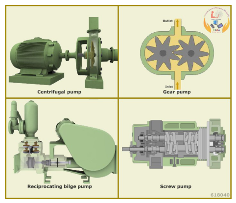
2. Before Starting Any Pump — the Common Checks
These apply to every pump type:
Confirm the pump is available for service — not under a permit to work, not isolated, not locked out.
Check the pump log and defect list.
Suction valve fully open. A partly closed suction valve is the commonest self-inflicted pump fault.
Discharge valve position correct for the pump type (see the starting sections below).
Check suction strainer / filters — differential pressure acceptable.
Confirm liquid is available at the suction source, and at adequate level.
Confirm priming for a centrifugal pump (casing full of liquid, all air vented).
Check gland/seal — packing in good order, mechanical seal not leaking, cooling/flush connections open if fitted.
Check bearing lubrication — oil level correct, grease adequate, oil condition (no water, no emulsion).
Check coupling — bolts, discs, distance piece, guard in place.
Check free hand rotation — the shaft should turn freely by hand (or with a bar as the maker permits).
Confirm the driver — insulation, supply available, and no lockout.
Confirm remote/auto controls — the pump must be removed from auto start and priority during maintenance, and restored afterwards.
3. Starting a Centrifugal Pump
3.1 Procedure
Open the air vent on the volute casing and open the inlet valve, so that all air is released from the casing. Close the vent once water starts to come out. (On a self-priming pump with an attached vacuum pump, ensure the priming water supply tank is full first.)
Close the discharge valve (or leave it in the throttled position specified).
Start the pump.
Open the discharge valve gradually. Meanwhile check the motor amperage — when the amperage drops, fully open the discharge valve.
Close the check valve on the attached vacuum pump line (self-priming types).
Check for leakage from gland packing, casing, or mechanical seal.
Monitor suction and discharge pressure, casing temperature, noise and vibration.
3.2 Why the discharge valve is closed on start
- At low head and high throughput the centrifugal pump motor can be overloaded — the opposite of the axial pump. Starting against a closed valve keeps the pump at its minimum power point.
- Opening the discharge valve gradually prevents a sudden hydraulic shock to the system.
- At shut-off, power consumed is minimum, and pressure rise is only moderate.
3.3 If it is a standby/auto pump
Restore auto-start and priority only after all checks are complete and the running pump has been proven. Remove from auto during any maintenance — this is a listed isolation step.
4. Starting a Positive Displacement Pump (Reciprocating, Gear, Screw)
4.1 Procedure
Suction valve fully open.
Discharge valve fully open — or the bypass/relief route established. Never start a PD pump against a closed discharge.
Confirm the relief valve between suction and discharge is free and correctly set.
Confirm priming — PD pumps are generally self-priming, but check the suction line is not dry and blocked.
Check lubricator / oil supply — reciprocating steam-driven pumps need cylinder lubrication; gear/screw pumps need the casing primed with oil.
Start the pump.
Check for pulsation — a reciprocating pump should have air vessels in good order to damp discharge pulsation.
Check relief valve is not passing (a partly open relief valve is a listed cause of low volumetric efficiency).
4.2 Air vessels
Air vessels are fitted on reciprocating pump discharge lines to ensure uniform water flow velocity in the discharge line, thereby reducing the inertia head required. The vessel is simply a cylinder forming an air space — a damping cushion — with fluid entry at one side and discharge over a weir at the other side, or via an internal pipe.
The air vessel works because the peak pressure energy is stored in the compressed air and returned to the system when pressure falls.
Air vessels are also fitted on the suction side of some reciprocating pumps. They are rarely fitted to centrifugal pumps, where steady flow and air extraction are usual instead.
5. Running Checks — What to Look at Every Round
5.1 Centrifugal pump
| Parameter | What to look for | What it tells you |
|---|---|---|
| Suction pressure | Steady, at or above design | Falling suction pressure = strainer choking, low tank level, air ingress, cavitation |
| Discharge pressure | At or near design for the duty | Low = wear rings worn, cavitation, wrong direction, impeller problem. High = throttled/fouled discharge |
| Motor amperage | Within rated, stable | Rising amps at constant duty = wear, blockage. Low amps with low flow = lost suction |
| Casing temperature | Normal for the liquid | High at low capacity = internal recirculation, overheating |
| Gland/seal leakage | Drop-by-drop from a packed gland | No leakage at all means the gland is too tight and will destroy the shaft sleeve |
| Bearing temperature | Steady, within limits | Rising = lubrication, alignment, or bearing failure |
| Vibration | Low and steady | Rising = misalignment, imbalance, wear ring contact, bearing failure, cavitation |
| Noise | Smooth | Crackling/gravel noise = cavitation. Rumbling = bearing. Knocking = coupling or loose part |
| Leaks | None from casing joints | Casing joint leak = gasket failure, distortion, thermal shock |
5.2 The gland packing rule
Make sure that there is a drop-by-drop leakage from the gland packing. This is not a defect — it is required for lubrication and cooling of the packing. A gland with no leakage will overheat, the lubricant will extrude, the packing will calcify, and the shaft sleeve will be destroyed (packing "stage four").
5.3 Reciprocating pump
- Pulsation — check air vessel charge and condition.
- Valve noise — broken or weak valve spring, cavitation, air leak in inlet piping, or air trapped above the inlet valve.
- Stuffing box leakage — worn packing, worn rods/plunger, worn stuffing box, wrong size packing.
- Power end temperature — running backward, RPM too low, insufficient or excessive oil, incorrect oil viscosity, over-pressure operation, tight main bearings, misalignment, tight belts.
- Liquid knock vs mechanical knock — differentiate. Liquid knock = cavitation or air. Mechanical knock = loose piston/plunger, worn crosshead pins and bushings, loose connecting rod cap bolt, worn connecting rod bearings, worn crosshead, excessive main bearing end play.
5.4 Gear and screw pump
- Backlash — measure with a dial indicator or feeler gauge at each overhaul and record for future reference.
- Bearing/bushing condition — listen for crude noise when turned by hand.
- Oil seal — check lips for wear; renew whenever the pump is dismantled.
- Discharge pressure — must not exceed the relief valve setting.
- Screw pump self-priming behaviour — if it stops priming, look for air ingress or a worn casing sleeve.
6. Flow Control
| Method | Effect | Comment |
|---|---|---|
| Throttling the discharge valve | Moves the operating point left along the pump curve | Simple, cheap, wasteful of energy. Never throttle the suction. |
| VFD / speed control | Follows the affinity laws | Most energy-efficient. Not suitable for head-critical duties at low speed. |
| Impeller trim | Reduces diameter | Permanent change; ~30 % energy saving for 10 % diameter reduction. |
| Bypass / recirculation | Diverts flow | Wastes power but keeps the pump away from its minimum-flow limit. |
| On/off (level control) | Intermittent running | Acceptable only where start frequency is within the driver's limits. |
Never control the flow of a positive displacement pump by throttling the discharge. Control by speed, by stroke adjustment, or by an internal bypass/relief.
6.1 Minimum flow protection
Many pumps require a minimum continuous flow — typically expressed as a percentage of BEP flow, and varying by liquid (e.g. for hydrocarbons, a stated minimum continuous flow as % of BEP flow on a non-trimmed impeller). Operating below minimum flow causes:
- Internal recirculation and cavitation-like damage.
- Rapid casing temperature rise.
- High radial loads and shaft deflection.
- Seal and bearing failure.
Where the process can demand less than minimum flow, an automatic recirculation line must be fitted.
7. Stopping a Pump
7.1 Normal stop
Reduce flow gradually where the system allows — avoid a sudden hydraulic shock.
Stop the driver.
Close the discharge valve.
Close the suction valve (only if the pump is being taken out of service).
Where the discharge is against a head, ensure the non-return valve holds and the pump is not left pressurised.
Record final readings and any defects noted.
7.2 Why not to stop a pump suddenly
- Water hammer in the discharge line.
- Sudden reversal of flow through the pump if the non-return valve is defective.
- Thermal shock if the pump is hot.
- On a positive displacement pump, an abrupt stop with a loaded discharge can damage the drive train.
7.3 Standby management
- Rotate running/standby pumps on a planned basis so that neither sits idle indefinitely.
- Prove the standby pump before you need it. A standby that has never been run is not a standby.
- Record running hours and reason for each changeover.
8. Planned Maintenance — What Gets Done and When
The actual intervals come from the maker's manual and the PMS. What matters is what is done:
| Item | Action |
|---|---|
| Gland packing | Check leakage; renew at packing "stage 3". |
| Mechanical seal | Check for leakage; renew on failure. Typical life 1–2 years, max 3. |
| Wear rings | Measure clearance; renew when beyond maker's limit. |
| Bearings | Check temperature, vibration, grease/oil condition; renew on deterioration. |
| Lubrication | Top up, sample for oil analysis, change at intervals. |
| Coupling | Check alignment, element/disc condition, key fit, bolts. |
| Strainers/filters | Clean; record differential pressure. |
| Relief valve | Check setting and freedom. |
| Instrumentation | Prove suction and discharge gauges, ammeter, pressure switches. |
| Vibration | Trend readings at each bearing. |
| Alignment | Re-check after any work on shaft, impeller, bearings, or foundation. |
8.1 The alignment rule
Alignment should be checked while the pump is warm, as the expansion due to heat while running would be different from the cold condition.
Alignment must be re-checked whenever the shaft, impeller, or any component is replaced, and when there is excessive whipping of the shaft.
9. Watchkeeping Discipline
- Trend, don't just read. A discharge pressure of 4.2 bar means nothing; 4.2 bar falling 0.1 bar per week means a wear ring or a strainer.
- Compare against the pump's own history, not just the maker's figure.
- Log every changeover with reason and running hours.
- Never leave a pump running that you have not checked since the last watch change without a note.
- Report and record the first sign of change — noise, temperature, pressure, vibration, leakage.