
Overhaul, Inspection and Repair
An overhaul done badly is worse than no overhaul — the damage is built in while the equipment is open.
Key Principles at a Glance 5 points
- Isolate, lock and tag, shut suction and discharge, then prove zero pressure through the purge cock — never rely on a closed valve alone.
- Mark the coupling and casing before separating, so reassembly is measurement, not guesswork.
- Wear ring clearance beyond the maker’s limit is a renewal, not an adjustment — and it should be measured and recorded every time.
- A fretting groove on the shaft under the mechanical seal is an alignment fault, not a seal fault. Replacing the seal will not fix it.
- Alignment must be checked while the pump is warm; cold readings do not represent the running condition for hot duties.
1. Safe Isolation — Before You Touch Anything
Never place dismantled parts directly on the floor or on a dirty workbench — always on a clean surface.
Before dismantling, check that the motor cannot be started by isolating the power supply.
The isolation sequence
Run the standby pump and stop the pump to be overhauled.
Control room circuit breaker off.
Electrical isolation permit obtained; local electrical panel circuit breaker off.
Lock it and tag it.
Shut the suction valve.
Shut the high-pressure discharge valve.
Check via purge cock that there is no pressure inside the pump.
Remove the pump from auto start and from priority.
Display 'men at work' warning board.
Mark the points on the coupling and casing with a marker before separating — so reassembly is not a guess.
Drain the casing and note where the liquid goes.
Where hot, allow to cool before opening. Where the liquid is hazardous, use the correct PPE and a permit to work.
On a centrifugal pump, confirm valves are holding by opening the purge/vent cock. Do not rely on a closed valve alone — a passing valve is a common cause of an unpleasant surprise.
2. Dismantling a Centrifugal Pump
Sequence
Remove the distance piece fitted between pump and motor coupling, after removing both motor-side and pump-side coupling bolts and discs.
Remove the cooling connections to the mechanical seal.
Remove the motor (with a chain block if required) and secure it separately. Apply insulation tape to its wires.
Remove the casing top cover bolts.
Once the casing cover bolts are removed, the pump assembly is free to remove — along with shaft, bearing housing, bearing, mechanical seal, impeller and impeller shaft with sleeve.
Slacken the impeller lock nut and remove the impeller from the shaft.
Remove the shaft key — take care not to lose it.
Remove the distance ring.
Slacken the holding screw and remove the mechanical seal's rotating part.
Slacken the bearing housing bolts fitted on the casing cover.
Remove the casing cover from the shaft.
Remove the shaft sleeve from the shaft.
Remove the bearing housing cover.
Remove the bearing retaining circlip.
Remove the bearing housing along with the bearing.
Remove the bearing from the housing using a bearing puller.
Bearing removal
Remove the bearing from its seat using a puller. If possible, let the puller engage the inner ring, then remove the bearing with a steady force until the bearing bore completely clears the entire length of the cylindrical seat.
Do not hit the bearing directly with a hammer. Shock loading brinells the races and destroys the bearing before it is ever run.
3. Cleaning and Inspection
The inspection list
Remove the bearing from the housing for inspection.
Clean the impeller, bearing, shaft sleeve, casing and shaft. Inspect and evaluate each part for damage, deformation, wear and tear.
Measure the clearance between impeller and wear rings — for both top and bottom wear rings. If clearance is more than the maker's recommendation, renew it.
Inspect the shaft sleeve for wear. If worn out, renew.
Check the condition of the bearing. If not good, renew.
Check the mechanical seal's rotary and stationary parts. If damaged, renew.
Check the bearing bush at the casing bottom and confirm any wear. If worn beyond acceptable limits, renew.
Impeller inspection
- Visually inspect for wear, erosion and cavitation damage.
- The impeller must not be excessively worn at any point, either from contact or from corrosion.
- The vanes at the eye and at the discharge are the trouble spots.
- Diffuser blades worn at the tips must be dressed up, to avoid stress raisers.
- Check for pitting, erosion or corrosion. If found, rectify with brass putty if practicable; otherwise renew.
Shaft inspection
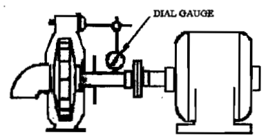
- Check the shaft for bending by putting it on a lathe and checking its trueness.
- Check the sleeve in way of the stuffing box — it is susceptible to damage from packing that has been excessively tightened.
- Check the shaft key slot for wear or deformation.
- Check the key for snug fit — a loose key leads to damage of the keyway and further problems.
Bearing inspection
- Shell-type bearings: check clearances with appropriate feeler gauges or lead wire gauge. Adjust for proper clearance by means of shims.
- Ball/roller bearings: check for roughness, discolouration, corrosion, and crude noise when turned by hand.
- Check the bearing housing for wear or scoring.
Seal inspection
Packing:
- Remove all of the old packing, taking care not to damage the shaft by scratches.
- Check the neck bushing clearance — if great, use a stiffer bottom ring or replace the bush.
- Check the shaft sleeve surface for grooving.
- Check the lantern ring and its supply passage for blockage.
Mechanical seal:
- Check the rotary and stationary faces for wear, cracking, chipping, heat checking.
- Check the O-rings/bellows for nicks, cuts, hardening, swelling, or sticking to the shaft.
- Check the springs for freedom — suspended solids, crystals and sediment can lodge in the springs and restrict movement.
- Check the shaft for a fretting groove under the seal — this indicates misalignment, not a seal fault.
- Check the seal chamber face is perpendicular to the shaft.
- Check the seal chamber bore for scale, and the flush/cooling passages for blockage.
4. Reassembly
Assembling is done in the reverse order of dismantling:
Pass the bearing housing through the shaft, then fit the bearing in the housing.
Fix the retaining circlip for the bearing and apply the required grease.
Fit the bearing housing cover.
Renew the top and bottom O-rings for the casing cover.
Fix the mechanical seal's stationary part with the casing cover.
Fit the shaft sleeve.
Pass the casing cover through the shaft.
Fix the mechanical seal's rotary part on the shaft sleeve and tighten the lock screw.
Insert the distance ring.
Fix the shaft key and secure the impeller.
Tighten the impeller by shaft nut and lock plate.
The impeller assembly is now ready for lowering into the pump casing.
Lower the impeller assembly and tighten the pump cover with the volute casing.
Tighten the bearing housing with the casing top cover.
Connect the cooling pipes for the mechanical seal.
Open liquid to casing, purge the casing, and confirm the mechanical seal is intact without leaks.
On confirming the pump is free to turn and the mechanical seal is not leaking, fit the distance piece for connecting pump and motor coupling, with the coupling discs.
Operate the pump and check performance by monitoring its parameters.
New bearing fitting
If bearings are worn out, replace with new (after discarding the cage and balls of the previous one).
Put the new bearing in lube oil and heat it.
Put it back on the shaft and slowly tap it to fit properly.
Packing installation — the correct technique
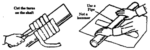
Find the right size of packing: measure the bore of the stuffing box and the diameter of the shaft. Subtract shaft diameter from inside bore, and divide by 2. This takes the guesswork out and ensures a perfect fit.
Cut the rings on the shaft — place the packing on the shaft to cut the rings. If you cut the ring by stretching out the packing, the ends will be at the wrong angle and sealing will be bad.
If used for high-temperature service, leave a slight gap between the rings to allow for expansion, otherwise the shaft may have excessive drag.
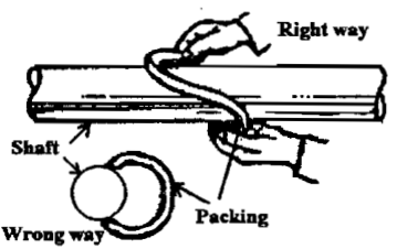
Slip the packing the correct way onto the shaft. When opening the ring, do it sideways to prevent distortion — especially with lead-filled or metallic types.
Swab the insides of metallic packing with the lubricant supplied with the packing, or a light oil, to keep the packing from scratching the shaft.
Stagger the joints of successive rings (never line them up).
Tighten the gland evenly, then slacken to give drop-by-drop leakage when running.
5. Alignment
Why it matters
After any overhaul or clearance adjustments, care must be taken on re-assembly to make sure motor or impeller are not pulling on each other at the junction coupling.
Alignment must be checked whenever the shaft, impeller, or any component is replaced, and when there is excessive whipping of the shaft.
The alignment checks
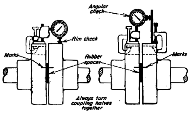
Make markings and remove the coupling bolts.
Rotate the coupling halves together — always turn them together, never one relative to the other.
Check for angular alignment (angular check) — the faces must be parallel.
Check for rim out-of-true (rim check) — the peripheries must be concentric.
Clean surfaces of pins and bushes, check for roundness, replace damaged bushes.
The pin must be a snug fit.
Check the elastic/rubber bushes for wear — normal clearance must be maintained.
The hot-alignment rule
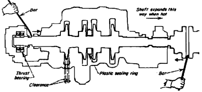
Alignment should be checked while the pump is warm, as the expansion due to heat while running would be different from the cold condition.
For high-temperature duties (feed pumps, hot oil pumps), set the cold alignment to compensate for expected thermal growth — the maker's manual gives the figures.
Alignment and the mechanical seal
A misaligned seal is not a seal problem — it is an alignment problem. If the mechanical seal is cocked or misaligned on the shaft, or the seal chamber face is not perpendicular to the shaft, the shaft O-ring must flex to maintain face contact. The flexing causes the seal to rub on the shaft under the seal, which can erode a groove into the shaft. The pumped fluid can then leak under the O-ring, or the O-ring can hang into the groove and drag the seal faces as the shaft moves within the bearing tolerance.
6. Overhaul of the Driver and Coupling
Removal:
- Remove the coupling bolts and the foundation bolts of the motor and slightly push the motor back.
- Take the shims from below the motor under the foundation bolts — these may have been used for alignment. Keep them in the same order for reuse.
- Remove the flange bolts in both inlet and delivery pipe lines. Inspect the joints for damage after the pump is removed from its foundation.
- Remove the foundation bolts and lift the pump with the inlet and delivery pipelines to the nearest place where it can be dismantled.
- Clean the foundation place while the pump parts are being cleaned.
- Remove the pipelines on the suction and delivery sides; pour any residual oil to a tray.
On reassembly:
- Place the pump on the cleaned foundation with the correct shims in place.
- Move the motor so that both flanges come close together.
- Keep the shims under the motor feet correctly.
- Check for any glaring misalignment.
7. Gear and Screw Pump Overhaul
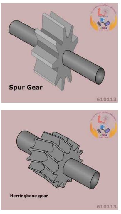
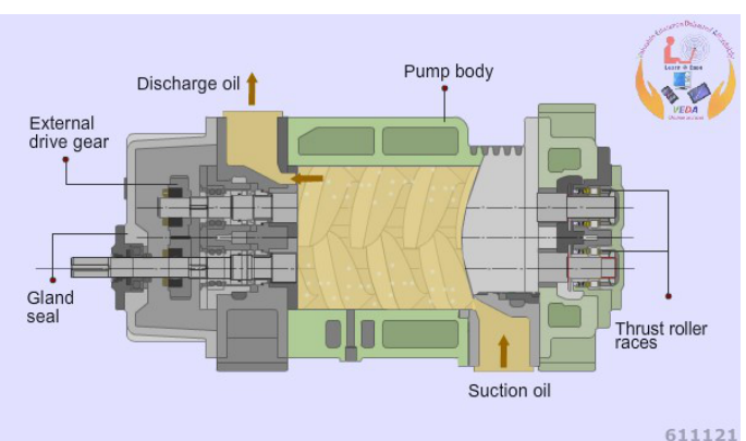
Preparations
Ensure the necessary spares are available — oil seal, bushings/bearings.
Switch off the power supply to the motor and remove the fuse.
Shut the outlet and inlet valves to/from the pump.
Keep a warning sign indicating that the motor must not be turned on.
Remove the coupling bolts and foundation bolts; push the motor slightly back.
Take the shims from below the motor feet — these may have been used for alignment. Keep them in the same order for reuse.
Remove the flange bolts on both inlet and delivery lines; inspect the joints for damage.
Lift the pump to the dismantling place; drain any residual oil to a tray.
Clean the foundation place while the pump parts are being cleaned.
Dismantling
Remove the drain plug and drain the oil to a tray.
Remove the bolts on the back cover and take it out carefully. Most manufacturers provide thread holes in the back cover on left and right — fit the correct bolts and tighten them equally; the bolts push the outer shell and loosen the grip, assisting release.
Note that each of the drive and driven shafts runs on two bushings/bearings — one pair in the back cover, one pair in the front of the shell.
Remove the driven (idler) shaft from both bushings.
Remove the drive shaft and gear — the gear may be keyed to the shaft, or integral with it.
Clean all parts.
The three checks on a gear/screw pump
Backlash clearance — if more than the permissible limit in the manual, the gears must be changed as a set. Record the backlash clearances for future reference. Measure with a dial indicator, or a feeler gauge on smaller pumps. Standard backlash: 0.02–0.15 mm. Maximum: 0.20 mm.
Bushings/bearings — if worn out, or if ball bearings produce a crude noise when turned by hand, they must be changed. Many manufacturers use ball bearings instead of bushings in high-capacity pumps to reduce frictional losses.
Oil seal — if the lips are worn or slightly damaged, renew. It is good practice to change the oil seal whenever the pump is dismantled, and always on a PMS or condition-based overhaul.
Also clean the joint seating faces on both the main shell and back cover; replace the joints if damaged.
Reassembly
Hold the back cover correctly in place while the gear/screw shafts enter the bushings.
Turn the drive shaft by hand — it should turn without any wobbling.
Tighten the back cover properly with a new joint; refit the drain plug.
Refit the inlet and outlet pipelines with proper thread seals.
Place the pump on the cleaned foundation with the correct shims, move the motor so both flanges are close, keep the shims under the motor feet correctly, and check for any glaring misalignment.
8. Repair — Temporary and Permanent
Shaft repair
Permanent: take out the sleeve and replace it with a new one, and fit a new O-ring.
Temporary repair of a worn shaft (if no spare is available):
Surface preparation — remove oil and grease.
Check the depth of the groove: if up to 25 mm shaft diameter, take a 2 mm cut; if about 25 mm shaft diameter, take a 3 mm cut.
After cleaning, make a dovetail → inside girder.
Make threads.
Apply DEVCON metal-filled epoxy (pot life about 20 minutes) — this will make it hard.
Let it dry and cure in the curing time.
Cut it on the lathe and do surface finishing using emery paper.
For a stainless steel shaft, stainless steel putty may be used.
Coupling repair
If the coupling is worn and no spare is available:
- Star coupling: put it in the opposite direction. Do not try to suddenly stop the pump.
- Pin and bush coupling: put rubber inside it.
Impeller repair
- Pitting, erosion or corrosion: rectify with brass putty if the damage is minor. If impossible to rectify, replace the impeller.
- Diffuser blade tips worn: dress up to remove stress raisers.
- Severe cavitation or erosion damage: replace. Do not attempt to weld-build an impeller unless the maker approves the procedure.
When to renew rather than repair
Renew (do not repair) if:
- Wear ring clearance is beyond the maker's limit.
- The shaft is bent beyond the maker's limit.
- The shaft sleeve is grooved deeply enough to damage new packing.
- Bearing races are pitted, discoloured or rough.
- The mechanical seal faces are cracked or heat-checked.
- The casing has cracks or has lost metal through erosion beyond limits.
- The impeller is perforated or its vane profile is destroyed.
9. Testing After Overhaul
Confirm free hand rotation of the pump — the shaft should turn without wobbling.
Confirm the motor can be turned freely by hand.
Open the vent and inlet valve so all air is released from the casing; close the vent when water starts to come out.
Check for leakage from gland packing, casing joints, or mechanical seal.
Check the alignment of the pump.
Grease the bearing or coupling as applicable.
Give a small kick and stop the motor to check for any noise or vibration.
Start the pump and open the discharge valve gradually.
Make sure there is drop-by-drop leakage from the gland packing.
Check the suction and discharge pressure.
Check the temperature of the casing.
Check for abnormal noise and vibration.
Monitor the motor amperage — when the amperage drops, fully open the discharge valve.
Restore the pump to auto start and priority, and remove the warning board and permit.
Record the overhaul, measurements, parts renewed, and post-overhaul performance in the pump maintenance file.
Baseline performance
Record, for each pump after overhaul:
These become the reference for all future condition monitoring. Without a baseline, a rising trend means nothing.
10. Component-by-Component Overhaul Summary
| Component | What to inspect | Renew when | Notes |
|---|---|---|---|
| Impeller | Wear, erosion, cavitation, contact marks, balance | Perforated, vane profile destroyed, severe erosion | Vanes at eye and discharge are the trouble spots |
| Wear rings | Clearance to impeller boss | Beyond maker's limit | Record measured clearance each time |
| Casing | Cracks, erosion, corrosion, joint faces, corrosion under insulation | Cracks, gross loss of metal | Check casing rings and locking pins |
| Shaft | Trueness (dial gauge on lathe), keyway, sleeve area | Bent beyond limit, keyway damaged | Alignment problem shows as a fretting groove under the seal |
| Shaft sleeve | Grooving, pitting, wear | Grooved or worn | Always renew the O-ring with it |
| Bearings | Roughness, discolouration, clearance, housing fit | Pitted, discoloured, rough, excessive clearance | Heat new bearings in lube oil before fitting |
| Bearing housing | Wear, scoring, seal faces | Worn | Check housing cover and circlip |
| Gland packing | Condition, stage of life, size | Stage 3 (lubricant extruded) | Never let it reach stage 4 |
| Lantern ring | Freedom, passage blockage | Blocked or damaged | Provides flush/cooling |
| Mechanical seal | Faces, O-rings/bellows, springs, installation dimension | Any face damage, O-ring damage, jammed springs | Check alignment before blaming the seal |
| Neck bush / bottom bush | Clearance, wear | Beyond limits | Adjust clearance with shims where fitted |
| Coupling | Alignment (angular + rim), pins, bushes, key, discs | Worn bushes, damaged pins, damaged key | Check alignment while warm |
| Foundation / shims | Condition, shim order, bolt tightness | — | Keep shims in the same order for reuse |
| Pipelines / supports | Joint condition, support adequacy, expansion | — | Inadequate support causes vibration |
| Relief valve (PD pumps) | Setting, freedom, passing | Passing or mis-set | Set per maker |
| Air vessel (reciprocating) | Air charge, internal pipe/weir | Air lost, internal damage | Dampens discharge pulsation |
| Instrumentation | Gauges, pressure switches, ammeter | Faulty | Prove after overhaul |
11. The Overhaul Record — What to Write Down
For every pump overhaul, record:
Pump identification / service:
Date in / date out / running hours:
Reason for overhaul:
Isolation reference / permit number:
Measurements taken (before):
  - Wear ring clearance, top / bottom:
  - Bearing clearance / condition:
  - Shaft trueness:
  - Sleeve condition:
  - Packing size fitted:
  - Backlash (gear/screw pumps):
Parts renewed:
Work carried out:
Measurements after reassembly:
Alignment readings (cold / hot):
Test results - suction, discharge, amps, temperature, vibration:
Defects outstanding:
Signature / Chief Engineer's review: