Centrifugal Pump Construction
Learn the parts and their failure modes, and most pump faults become diagnosable.
Key Principles at a Glance 5 points
- Impeller speed and diameter determine the head; impeller speed and blade height (width) determine the flow.
- Wear ring clearance increase is the single most common repair fault on centrifugal pumps — it connects suction to discharge and drastically reduces efficiency.
- The shaft must be constrained axially at only one location so it is free to expand and contract; a rigidly coupled pump is supported by the thrust bearing in its driver.
- Gland packing has four stages — change it at stage three, when the lubricant has extruded. Stage four destroys the shaft or sleeve.
- The back pull-out feature exists to allow rapid and frequent impeller change, not primarily to ease maintenance.
1. The Anatomy of a Single-Stage Centrifugal Pump
Everything else in these notes is a variation on this assembly. Learn the parts, learn their failure modes, and most pump faults become diagnosable.
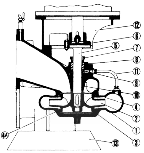
Numbered parts of the pump above:
| # | Part | # | Part |
|---|---|---|---|
| 1 | Pump casing and cover | 8 | Packing |
| 2 | Impeller | 9 | Lantern ring (split) |
| 3 | Casing ring (bottom) | 10 | Neck bush |
| 4 | Casing ring (top) | 11 | Water service pipe to stuffing box |
| 4A | Locking pins | 12 | Motor stool |
| 5 | Pump spindle | 13 | Pump foot |
| 6 | Coupling (motor half) | ||
| 7 | Gland |
1.1 The impeller
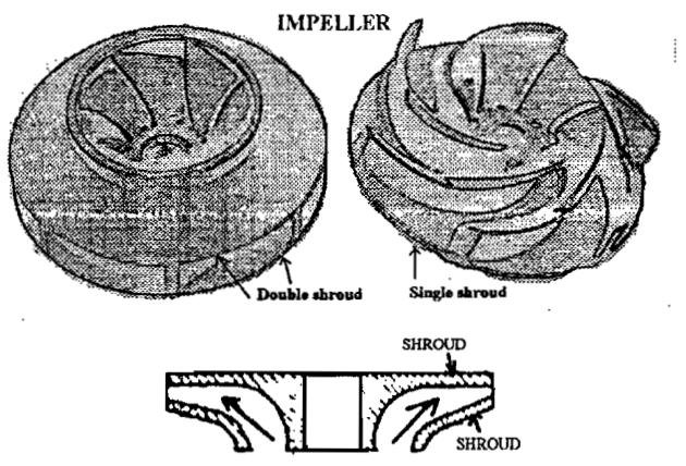
The impeller receives the pumped liquid and imparts velocity to it. It looks like a modified propeller.
Impeller speed and diameter determine the head the pump can generate; impeller speed and blade height (width) determine the flow.
Remember also that pumps do not actually generate flow — no pump converts 3 gpm at suction into 4 gpm at discharge. The term is industry shorthand for "the system allows this much through."
1.2 The casing
The casing is a pressure-containing boundary. Its thickness must withstand the design pressure, and its structure must withstand not only hydrostatic pressure but also stresses from the vessel's motion. External ribs may be added for strength.
The casing does two jobs:
- It converts velocity energy into pressure energy.
- It guides the liquid discharged from one stage to the inlet of the next (multi-stage), or to the pump outlet.
2. Casing Types
2.1 Volute (scroll) casing
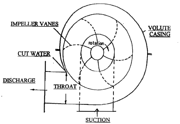
The volute has a gradually increasing radius and cross-sectional area surrounding the periphery of the impeller. The increase in volume converts kinetic energy into pressure head. Used with many single-stage radial and mixed-flow pumps.
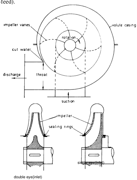
Key detail — the cut water. The radial clearance between the outside diameter of the impeller and the volute's tongue must be small to limit leakage. But if the gap is too small, excessive pressure pulsations, turbulence and noise result. This cut-water clearance is set to optimise performance while allowing a range of impeller diameters to be used with the same casing.
The volute may be designed either for constant average fluid velocity in all sections at design capacity, or for constant angular momentum at design capacity.
Concentric collector: some pumps use a circular collector of constant radius and cross-section. Except at shut-off, the velocity in this type increases from tongue to throat. A semi-concentric casing keeps radius and area constant over only part of the circumference.
2.2 Diffuser casing
A ring of diverging stationary vanes (multi-vaned diffuser) surrounds the impeller. Pressure recovery is accomplished in the limited space between adjacent stages, so multi-vaned diffusers are standard in multi-stage pumps — and in some single-stage radial pumps because of their high peak efficiency.
The stationary pieces separating adjacent stages are called stage pieces. The rotor plus stationary diffusers and stage pieces can often be inserted into a radially split casing as an assembled cartridge — because of the cylindrical casing shape these are frequently called "barrel" pumps.
2.3 Vane-less diffuser casing
Used when a wide range of operation is anticipated. Neglecting friction, fluid passing through the channel (constant width, or flaring slightly outwards) follows free-vortex flow; for parallel walls the reduction in velocity is proportional to the increase in radius.
2.4 Axially split vs radially split casings
- Axially split: flow passages between stages (crossovers) either integrally cast or welded. Common in volute-type multi-stage pumps.
- Radially split: the cartridge design above; typical of barrel pumps.
- The casing usually has suction and discharge branches arranged at the back so that impeller and spindle can be removed from the front without breaking pipe joints. The discharge branch is usually on the pump centre line so the pump is not "handed".
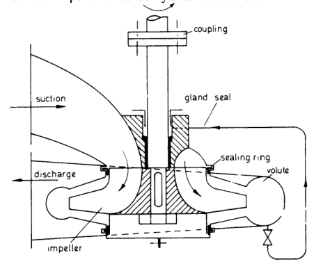
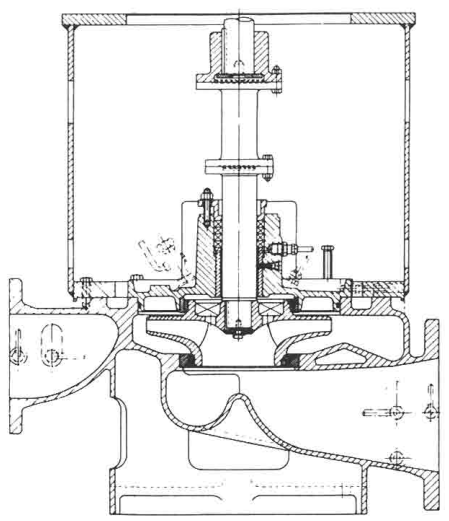
The vertically arranged pump above has the casing split vertically, one half carrying suction and discharge branches, so impeller and shaft can be removed without breaking pipe joints. The impeller has a single eye facing upwards so air locking is eliminated; pressure in the space under the impeller gives hydraulic balance.
3. Wear Rings and Running Clearances
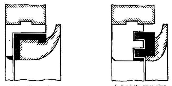
Wear rings (also called sealing rings, casing rings, neck rings) maintain a proper clearance between impeller and casing, controlling internal leakage from discharge back to suction.
- On the larger pumps, these faces are often brass strips on liners secured by countersunk screws; clearance adjustment is effected by adding further liners.
- On smaller pumps the faces are made by sealing rings which are renewable.
- Sometimes rotating wear rings are fitted on the outer hubs of the impeller. Serrations or grooves on the inside surface reduce leakage, reduce damage if the impeller is forced towards the casing by a transient external force, and lessen damage from trapped foreign bodies.
- In multi-stage pumps, replaceable bushes are used to limit leakage and maintain proper clearances.
- Types include plain, L-shaped and labyrinth wear rings.
This is the single most common repair fault on centrifugal pumps: increase of clearance due to wear at the bearing rim (sealing ring) faces. This allows connection between suction and discharge, drastically reducing efficiency.
Wear rings are not there to wear — their function is to control the tolerance and efficiency of the pump. They are therefore not necessarily made of metal.
4. Shaft, Bearings and Thrust Balance
4.1 Shaft and thrust
The net axial and radial loads on the rotating assembly are transmitted to the bearings. The thrust bearing absorbs axial loads.
The shaft must be free to expand/contract with changes in axial load or temperature, so it should be constrained axially at only one location.
A pump shaft rigidly coupled to its driver is therefore generally not fitted with a separate thrust bearing — it is supported axially by the thrust bearing in the driver. The remaining pump bearings, configured to absorb only radial loads, are called line bearings.
In a single-stage pump with the impeller centred on the rotor, a bearing is installed at each end of the shaft.
Hydraulic axial balance is achieved by:
- Double-entry impellers (thrust largely balanced by symmetry).
- Balance holes in closed impellers (API pumps) — these reduce stuffing box pressures and balance axial loading.
- Back wear rings / balance drums in multi-stage pumps.
4.2 Bearings
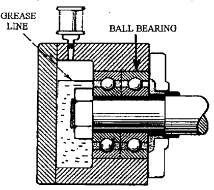
The type used depends on the magnitude and orientation of applied loads, temperature, speed and lubrication method.
- Grease is easier to apply than oil and keeps contaminants away from the running surface. If heat generated is negligible, oil is not necessary.
- Bearing seals prevent dirt and moisture travelling along the shaft into the bearing.
Causes of bearing overheating (memorise this list — it is a standard oral question):
- Grease/oil level too low, or improper grade.
- Dirt in the bearing, or moisture.
- Bearing too tight.
- Oil seals fitted too closely on the shaft.
- Misalignment.
5. Shaft Sealing — Gland Packing
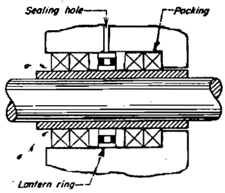
The opening where the shaft emerges from the casing must be sealed to prevent leakage. The casing is stationary and the shaft rotates at high speed, so this is difficult. Multiple packing rings inside a gland has traditionally been the answer: least friction, easy to replace, cheap.
- The portion of the shaft in way of the packing is protected by a sleeve, which is hardened or has a wear-resistant coating.
- To limit the temperature rise from friction, a certain amount of controlled leakage is allowed, adjusted by tightening/loosening the gland.
- Where the base of the stuffing box may be under vacuum, high-pressure liquid is injected through a lantern ring (seal cage) sandwiched between two of the intermediate packing rings.
- Where the fluid is contaminated, a lantern ring allows clean liquid to be injected to flush contaminants away from the packing.
- Where clean high-pressure liquid is impractical, grease is sometimes injected through the lantern-ring connection.
5.1 The four stages in the life of a packing ring
This is the most useful practical concept in packing maintenance:
Stage 1 — the rings occupy the full space inside the stuffing box.
Stage 2 — the gland has been tightened and the packing compresses; the space occupied is reduced.
Stage 3 — the lubricant has extruded from and left the packing. At this point the packing should be changed.
Stage 4 — no lubricant remains and the carrier fibers have disintegrated into ashes. The packing becomes hard from calcification and destroys the shaft or sleeve.
When the gland follower butts against the stuffing box mouth and the gland nuts can no longer be tightened, you have reached stage four. Stay away from stage four. Change at stage three.
5.2 Packing lubricants
Graphite is the common general-service lubricant. Molybdenum disulfide (moly grease) is excellent — it creates a lubricating film barrier between shaft and packing and works well at high temperature. Mica is good for very high temperatures but contaminates the pumped liquid with particles (never in a milk pump). Any oil compatible with the pumped liquid is adequate as a general lubricant. Many pumps use cold water flushed into the stuffing box as both coolant and lubricant.
Be aware that the packing is destined to fail the moment it is installed — it must resist every basic operating tendency of the pump, it consumes energy, and it generates frictional heat by grabbing and abrading the shaft.
6. Shaft Sealing — Mechanical Seals
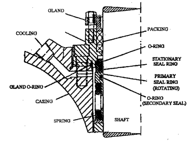
A mechanical seal is an improved form of sealing. It reduces shaft sleeve wear and does away with the continuous leakage that must be tolerated with conventional gland packing.
The primary sealing surfaces are the polished faces of one stationary ring and one rotating ring, separated by a thin film of liquid. Secondary sealing is by O-rings or elastomeric bellows.
6.1 Advantages
- Lower frictional drag than traditional packing → improved pump efficiency.
- Will not wear out a shaft or sleeve as fast as packing rings.
- Near zero leakage is possible; packing requires some visible leakage for lubrication.
- Properly applied, requires less periodic maintenance than packing.
- Specially designed seals can be applied to higher pressures and speeds than traditional packing.
6.2 Disadvantages
- Less tolerant to shaft deflection and misalignment.
- Less tolerant to dirty or contaminated liquid — will require a cyclone separator to clean the liquid.
- Requires expensive seal piping to flush and quench.
- More expensive than packing rings.
6.3 The most suitable configurations
- Bi-directional operation.
- Flexible shaft attachment by means of an elastomeric bellows (automatic compensation of seal seat wear by the integrated spring).
- Hard/soft material combination — ceramics or hardened metal running against carbon — offering optimum lubricating qualities.
- Attachment to a bronze or stainless steel shaft sleeve.
Service life is typically 1 to 2 years, maximum 3 years. Extremely bad water (sediments, additives, overheating) can severely shorten this; in such cases check suitability or the need for special designs with the seal manufacturer.
6.4 Practical seal arrangements
- Split mechanical seal: sealing elements split into halves so they can be replaced without removing other pump parts — avoids the time-consuming partial disassembly normally needed to pass a new seal over the shaft end.
- Auxiliary packing: two or more rings of packing can be installed in the stuffing box so the pump can keep running until the mechanical seal is replaced. Because this packing would receive no lubrication while the mechanical seal is working properly, it must be installed only after a seal failure has occurred.
- Jacket cooling: when pumping high-temperature fluids, gland packing and mechanical seals are often cooled by circulating liquid through a jacket surrounding the sealing area.
- Discharge bypass caution: the discharge re-circulation line is a legacy of the packing era. With a mechanical seal in slurry service, a discharge bypass line blasts the seal with the highest concentration of solids in the pump and destroys it. If cooling/flushing is wanted, a suction bypass (seal chamber to pump suction) is preferred over a discharge bypass.
6.5 Seal chamber pressure
This is the pressure measured in the stuffing box or seal chamber — the pressure the seal must hold. It must be within the limits of the mechanical seal. With double mechanical seals it governs the pressure setting of the barrier fluid.
7. Other Seal Types
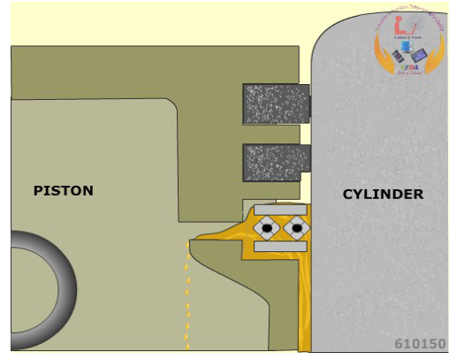
Rotary packing (used on larger pumps): a fixed clamp ring on the shaft drives another ring cup through driving pins, with packing rings on to the shaft. Ring cup and rings are free to slide along the shaft under axial springs from the clamp ring. The cup ring presses on to a fixed ball ring sitting in a ball socket joint in the back plate bolted to the pump casting. Grease lubrication is provided to the face between ring cup and fixed ball ring, worked by spring or water pressure.
Lead foil packing: used in small water-cooled stuffing boxes. These packings are very prone to nip and score the shaft severely if not properly adjusted.
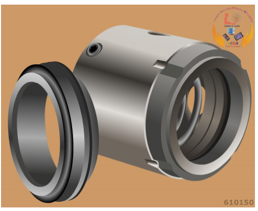
Labyrinth seals (e.g. turbocharger, auxiliary steam turbine): leakage is reduced by a tortuous path of fine clearances. Within the cavity where flow is turbulent, gas velocity is increased with an associated pressure drop; kinetic energy is dissipated by change of direction, turbulence and eddy currents.
8. Pump Materials by Service
| Service | Casing | Impeller | Shaft | Wear rings / bushes |
|---|---|---|---|---|
| Fresh water | Cast iron | — | — | — |
| Salt water | Gunmetal | Aluminium bronze | Stainless steel | Leaded bronze |
| Sea water circulation (axial) | Gunmetal (cast iron for heeling/trimming) | Aluminium bronze | Stainless steel with renewable stainless sleeve | Gunmetal guide vanes |
| Boiler feed (high pressure/temp) | Cast steel | Stainless steel | Stainless steel | — |
| Chemical cargo | Stainless steel | Stainless steel | Stainless steel | — |
| Liquefied gas (low temperature) | Nickel steels | Nickel steels | Nickel steels | — |
A pump handling liquids containing abrasives suffers erosion on all internal surfaces, including bearings and shaft seals. Sea water circulating pumps in silty/sandy waters require frequent renewal of shaft seals/packing and shaft sleeves in way of gland and bearings. Impellers may suffer perforations and massive enlargement of wear ring clearance. Protection can be provided by a water service to the shaft washing solids away from the seal area, and by mounting bearings external to the casing.
9. The Back Pull-Out Feature — and What It Is Actually For
Many engineers believe the back pull-out feature exists to facilitate maintenance. It does not. The back pull-out pump exists to facilitate rapid and frequent impeller change, adapting the pump to the ever-changing needs of production — because pumps are usually sold with only one impeller, when they should be sold with several diameters ready to be changed as duty changes.
A back pull-out pump allows the rotating assembly to be removed without disturbing the motor or the pipework — which does help maintenance, but that is a side benefit.
10. Other Construction Variants Worth Knowing
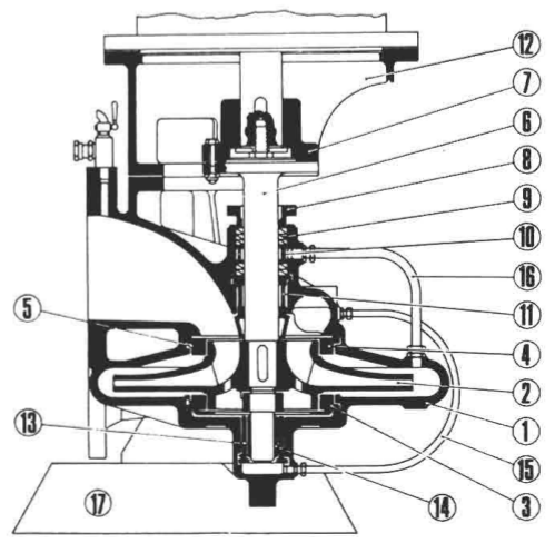
Where a single-entry pump must supply a large pressure head, an impeller of greater diameter is used. The model above also has a vertically split casing and an impeller eye facing upwards. The added lower guide bush is deemed necessary for the larger diameter impeller.
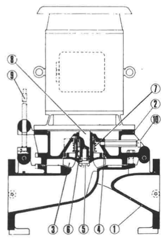
A novel design for ease of maintenance: the impeller eye faces downwards but the impeller is open-sided, with the bottom of the casing effectively shrouding the vanes. The motor and cover can be tilted on a hinge so that operation of a simple screw jack exposes the internal parts. A mechanical seal prevents water leakage or air ingress. Designed for a wide range of capacities by fitting an impeller of suitable diameter and tip width.
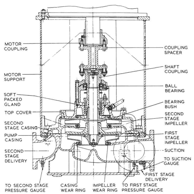
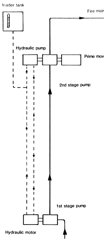
A two-stage pump may be installed as a fire and general service pump. Because both low and high head are available from the one pump, it can be used for double duty — lower head by pumping through the first stage impeller only, higher head through both impellers.