
Performance, Curves, Affinity Laws and the System
A pump is sold as a curve, not as a number — understanding the curve is what separates an engineer from an operator.
Key Principles at a Glance 5 points
- The H–Q curve descends: as flow increases, head falls. This one fact explains throttling control, discharge-valve starting procedure and why a restricted discharge reduces flow.
- Minimum power is consumed at no flow with the discharge closed — which is why a relief valve is not necessary on a centrifugal pump.
- Doubling the speed multiplies flow by 2, head by 4, and BHP, wear, downtime and friction losses by 8. Halving it divides them by the same amounts.
- The system controls the pump: the operating point is where the pump H–Q curve intersects the system curve, and nowhere else.
- Pumps should run in a band around the BEP — typically 70–120 % of BEP flow.
1. The Vocabulary
Understanding the curve is what separates an engineer from an operator.
| Term | Symbol | Meaning |
|---|---|---|
| Flow = Capacity | Q | Liquid volume per unit time — gpm, l/min, m³/h |
| Head | H | Liquid force expressed as feet (or metres) of elevation. Convertible to psi. |
| Brake horsepower | BHP | Energy needed to pump a liquid — the power drawn at the coupling |
| Speed = velocity | N | Shaft speed in rpm |
| Water horsepower | WHP | Useful hydraulic power delivered to the liquid |
| Total dynamic head | TDH | The total head the system demands |
2. The H–Q Curve
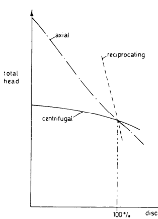
From a mathematical consideration of the action of a centrifugal pump, the theoretical relationship between head H and throughput Q is a straight line, with minimum throughput occurring when the head is maximum.

Because of shock and eddy losses caused by impeller blade thickness and other mechanical considerations, there is some head loss, increasing slightly with throughput. These losses, together with friction losses due to fluid contact with the casing, plus inlet and impact losses, result in the actual H/Q curve shown above.
The H–Q curve is in a descending profile: as flow Q increases, head H (pressure) falls. If flow is reduced, the pressure rises. This single fact explains throttling control, discharge-valve starting procedure, and why a restricted discharge reduces flow.
Key features of the curve:
- Shut-off head — the head at zero flow. Centrifugal pumps can be designed with relatively flat curves, or steep curves to give a relatively large shut-off head.
- The shape varies according to the design and features of the particular pump.
2.1 Where the curve comes from
A characteristic curve for a centrifugal pump is obtained by:
- Operating the pump at rated speed with the suction open and the discharge valve shut.
- Opening the discharge valve in stages to obtain different discharge rates and total heads (measured by discharge pressure gauge, suction head constant).
2.2 The power curve and the relief-valve question
From the H–Q curve and from HP/Q, the power curve: minimum power is consumed by the pump when there is no flow and the discharge head is at its highest — i.e. with the discharge valve closed.
Because maximum pressure with the discharge closed is only moderately above working pressure, a relief valve is not necessary for a centrifugal pump.
Also: if the discharge were choked or blocked, the pump would merely churn water — again confirming that a relief valve is not essential.
2.3 The efficiency curve
The efficiency curve for the pump is convex, which means maximum efficiency occurs at a point somewhere between maximum and minimum discharge head and throughput conditions. That point is the Best Efficiency Point (BEP).
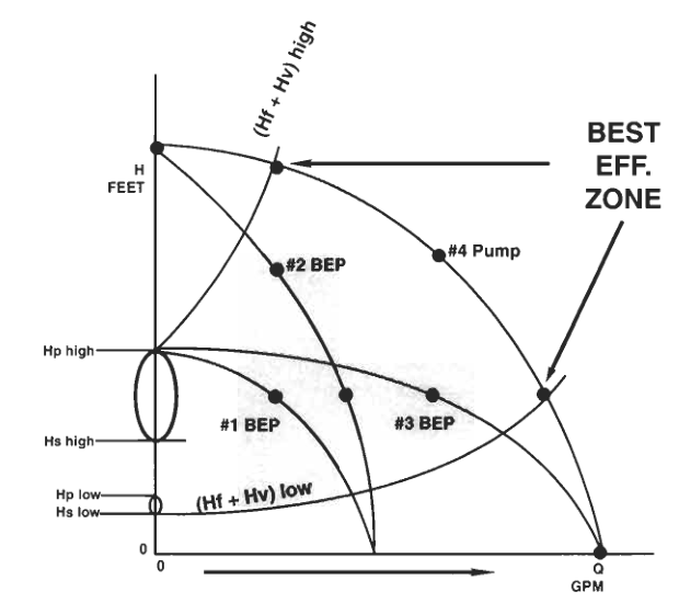
Pumps operating away from their BEP develop hydraulic side loads that can stress the shaft, damaging the bearings, wear bands and mechanical seal. Dual volute casings tend to equalize the radial hydraulic forces around the impeller, thus expanding the operating window of the pump.
3. Performance Variation with Impeller and Speed
3.1 Different impeller diameters at constant speed
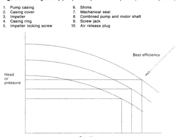
A set of performance curves can be obtained reflecting operation with different impeller diameters. A similar effect would be produced by using different speeds.
3.2 Different impeller widths at constant speed and diameter
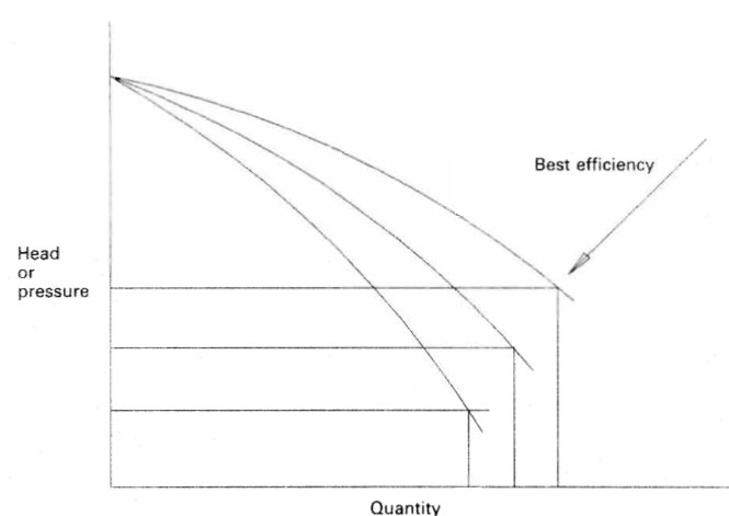
Variation of capacity at constant speed and diameter, facilitated by fitting impellers of different widths, produces a different type of performance variation. These curves also have points where performance is highest.
By altering impeller diameters and widths, a pump can be tailored to requirements. Performance is dictated by speed of rotation, impeller diameter, and the area of the flow passage through the impeller (i.e. width).
4. The Affinity Laws
The Affinity Laws (also called the Laws of Similarity) govern how a pump's characteristics change when speed or impeller diameter changes.
Originally used to predict pump operation when exported to a country with a different electrical frequency (50 Hz vs 60 Hz → different motor rpm). With the arrival of the Variable Frequency Drive (VFD), they have become increasingly important for industrial pumps.
4.1 Speed change (N)
- Flow varies directly with speed: Q ∝ N
- Head varies as the square of speed: H ∝ N²
- Power varies as the cube of speed: BHP ∝ N³
4.2 Impeller diameter change (D) — "trimming"
- Flow varies directly with diameter: Q ∝ D
- Head varies as the square of diameter: H ∝ D²
- Power varies as the cube of diameter: BHP ∝ D³
4.3 The consequences table — memorise this
Doubling the speed gives:
| Quantity | Multiplier |
|---|---|
| Flow / capacity / gpm / production | × 2 |
| Head / pressure (psi) / NPSHr | × 4 |
| Misalignment in the bearings | × 4 |
| BHP requirements | × 8 |
| Maintenance costs | × 8 |
| Downtime | × 8 |
| Erosion in pipes and elbows | × 8 |
| Impeller wear | × 8 |
| Wear in wear rings | × 8 |
| Other close-tolerance wear | × 8 |
| Friction losses (Hf) in pipes, fittings, valves | × 8 |
Conversely, halving the speed divides flow by 2, head by 4, and BHP by 8.
If plant operations don't depend on time — for example, if you have all night to drain a tank — the pump can run at 50 % speed while consuming one-eighth the BHP. Controlling flow with a VFD is better than using a constant-speed motor and throttling.
Efficiency effect: with a small change in velocity (say 20–50 rpm) efficiency is not affected. With a doubling or halving of speed, expect a change of about 2–3 % — efficiency tends to increase a couple of points at twice the speed, and decrease a couple of points at half speed.
4.4 The caution — head-critical applications
Not every application tolerates a VFD. Some centrifugal pumps must comply with head, pressure and elevation requirements — for example a boiler feed water pump, or a pump pushing fluid through a filter. In these applications the VFD may only be effective at 85 % to 100 % maximum speed, because running at 50 % speed would generate only one-quarter the head.
4.5 Impeller trimming in practice
Consider sterile water for injection: boiling at 35 psi and pumping 40–70 gpm according to consumption. The 35 psi is a constant for the water to pass through the heat exchanger and a bank of filters. Varying the impeller diameter lets the same pump and motor deliver 40, 50 or 70 gpm at 35 psi. This precise manipulation could not be obtained by opening and closing valves, or by simply controlling pump speed with a VFD.
Energy example: a pump consuming 10 BHP with a 10-inch impeller would consume only 7.3 BHP with a 9-inch impeller. A 10 % reduction in impeller diameter brings about almost 30 % reduction in energy.
5. The System Curve and Total Dynamic Head
All pumps must be designed to comply with, or meet the needs of, the system. The needs of the system are recognised using the term Total Dynamic Head (TDH). The pump reacts to a change in the system.
5.1 The four heads that make up TDH
- Hs — static head: the change in elevation of the liquid across the system (suction vessel level to discharge vessel level).
- Hp — pressure head: the difference in pressure between the two vessels (e.g. a pressurised tank, or a closed system). 10 psi = 23.1 ft of Hp.
- Hv — velocity head: the energy lost into the system due to the velocity of the liquid. Hv = v² / 2g.
- Hf — friction head: friction losses in the system expressed in feet — for pipe, valves and fittings.
5.2 The point of operation
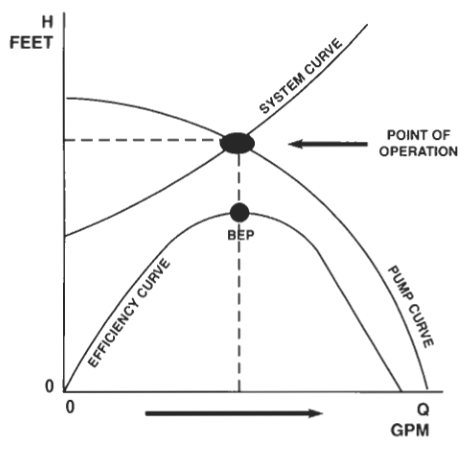
The operating point is where the pump H–Q curve intersects the system curve. The pump will run at that flow and head, and nowhere else.
- If the system resistance increases (valve throttled, fouled pipe, higher discharge level), the system curve steepens and the operating point moves left — lower flow, higher head.
- If system resistance decreases, the operating point moves right — higher flow, lower head, and higher power absorbed (for a centrifugal pump).
5.3 Variable resistances over time
- Short-term resistance changes: valve movement, level change, temporary blockage.
- Long-term resistance changes: pipe fouling, scale, wear of fittings, permanent process change.
This is why a pump that was correct when commissioned may be wrong five years later.
5.4 Pumps in parallel and in series
- Pumps in parallel: flows add at a given head. Used where flow demand varies widely and where standby capacity is needed. Caution: two pumps in parallel each run further left on their curve than one alone, and the combined flow is not double unless the system is flat.
- Pumps running in series: heads add at a given flow. Used for high-head duties (multi-stage is effectively series stages in one casing).
- Combined parallel and series operation is used in complex systems (e.g. boiler feed with multiple pumps and stages).
5.5 The "happy zone"
Pumps should operate in a band around the BEP — typically 70–120 % of BEP flow. Outside that band:
- Far left of BEP: recirculation, high radial loads, vibration, shaft deflection, seal and bearing damage, high temperature rise in the casing.
- Far right of BEP: cavitation risk, high NPSHr, motor overload, erosion.
6. Specific Speed — Classifying Impellers
Definition: the Specific Speed Ns is the revolutions per minute at which a geometrically similar impeller would run if it were of such a size as to discharge one gallon per minute at one foot of head.
Where N = speed in rpm, Q = flow at BEP in gpm, H = discharge head at BEP. For double suction impellers, use ½ BEP flow.
6.1 What the value tells you
| Ns range | Impeller type | Character |
|---|---|---|
| 500 – 1,500 | Radial vane | Head generated by pure centrifugal action. High head, low flow. |
| 1,500 – 7,000 | Francis / Mixed vane | Head from a mixture of centrifugal action and impeller design. Popular in multi-stage vertical turbine pumps. Wider vanes → better at flow, less at head. |
| 7,000 – 20,000 | Axial flow | Almost exclusively high flow, little head. |
The Ns is also a guide in selecting the volute design — single or double volute — and is useful in analysing a problematic pump and in purchasing a new pump.
6.2 Useful work and efficiency
- Useful work from a pump = the hydraulic energy delivered to the liquid.
- Pump efficiency = useful work ÷ BHP.
- Factors that affect efficiency: internal leakage through wear rings and balance devices, friction in bearings and glands, disc friction on impeller surfaces, shock and eddy losses at vane entry and exit, and the volute/diffuser conversion efficiency.
Losses that must be accounted for when sizing the driver:
- Friction loss in bearings and glands, and on the surfaces of impeller and casing. (Some impellers are highly polished to minimise friction loss.)
- Head loss in the pump due to shock at entry and exit to impeller vanes, and eddies formed by vane edges.
- Leakage loss in thrust balance devices, gland sealing, clearances between cut water and casing, and bearing seals.
7. Pump Classification by Construction and Duty
Useful for oral exams and for pump selection:
- Overhung impeller — impeller at the end of the shaft, supported from one side.
- Impeller between the bearings — more rigid, used for higher loads.
- Turbine pumps — diffuser type, often multi-stage deepwell.
- Typical ANSI pump — one stage, end suction, back-pullout construction; weight and foot supports mounted on the shaft centreline; closed impeller with balance holes to reduce stuffing box pressure and balance axial loading.
- API pumps (API 610) — for non-corrosive liquids at high temperature and pressure; closed impellers with balance holes; designed for services above 350 °F; minimises pipe strain and thermal expansion/distortion.
- Vertical turbine pumps — submerged impellers, diffuser bells, no priming required.
- Non-metallic, magnetic drive, canned motor — see the pump principles topic.