
Pumping Systems Onboard
A pump is only as good as the system it sits in — most "pump problems" turn out to be system problems.
Key Principles at a Glance 5 points
- Every vessel must be arranged so that a bilge suction pipe severed by collision or grounding cannot flood another watertight compartment.
- The bilge injection valve diameter must be at least two-thirds the diameter of the main sea inlet.
- The axial flow pump dominates main condenser circulating duty because it idles with little resistance, is reversible, and allows a smaller motor at higher speed.
- Bilge overboard discharge requires the ship to be on passage, at least 12 nautical miles from land, outside a Special Area, with an approved separator and a working oil content meter.
- Never throttle the suction of any pump — control on the discharge or by speed.
1. Overview — the Main Pumping Systems
A pump is only as good as the system it sits in. Most "pump problems" reported by the duty engineer turn out to be system problems.
| System | Duty | Typical pump |
|---|---|---|
| Bilge | Drain water from any compartment under damage conditions | Centrifugal (self-priming) + reciprocating; emergency bilge pump |
| Ballast | Trim, list, draught control | Centrifugal |
| Fire main | Firefighting, deck wash, general service | Centrifugal, often two-stage; emergency fire pump |
| Sea water cooling | Main condenser circulating | Axial flow (reversible, scoop-assisted) |
| Sea water cooling (auxiliaries) | Generators, coolers | Centrifugal, vertical in-line |
| Feed water | Boiler feed | Multi-stage centrifugal / turbo-feed |
| Condensate | Extraction from condenser / de-aerator | Multi-stage centrifugal with air pump |
| Fuel oil | Transfer, settling, service, burner feed | Screw, gear, reciprocating |
| Lubricating oil | Main engine and auxiliary LO | Screw or reciprocating |
| Cargo | Discharge of liquid cargo | Large centrifugal (crude); deepwell/submerged (product, chemical, gas) |
| Stripping | Final draining of cargo tanks | Screw (self-priming) or reciprocating |
| Steering gear | Hydraulic power | Variable-delivery axial piston, Hele-Shaw |
| Oily water separator feed | Bilge treatment | Small centrifugal/PD with OWS |
| Sewage | Treatment plant | PD or centrifugal |
2. Bilge System
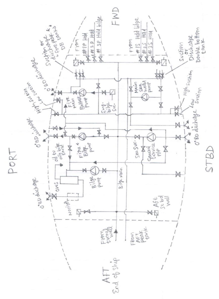
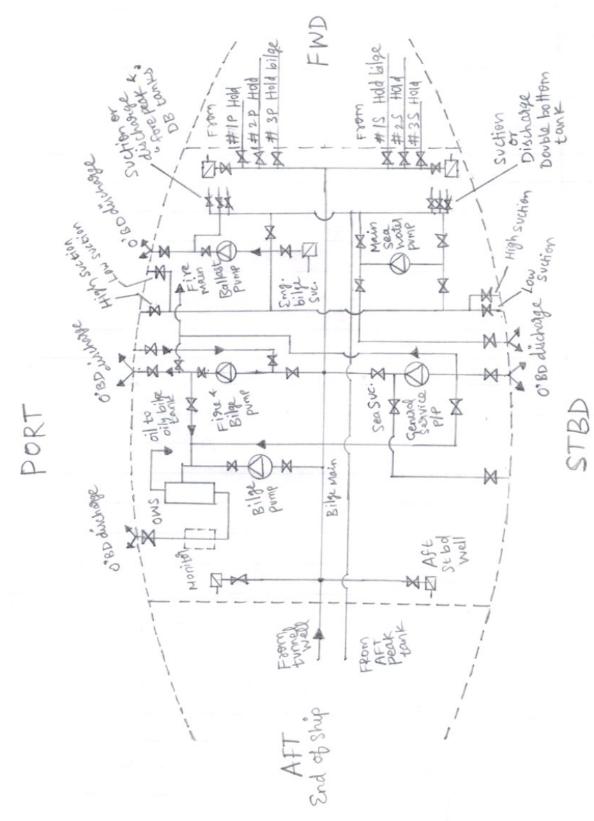
2.1 Purpose
To pump out and drain any watertight compartment (including tween decks) adjacent to a damaged compartment, under all reasonable damage conditions. Efficient drainage must be provided especially to unusual-form compartments, and the piping system design must not allow flooding under damage conditions.
2.2 The rules (vessels over 90 m long) — the ones worth knowing
At least four independent power pumps connected to the main line. Ballast, sanitary etc. are acceptable, also an engine-driven pump, provided they are of sufficient capacity and connected to the main line.
One such pump should be of the remote-controlled submersible type, or the power pumps and controls so placed that one pump is always available under all reasonable damage conditions. Each pump should where possible be located in a separate watertight compartment.
Pumps should be of the self-priming type unless efficient priming devices are provided.
Pump capacity should give a water speed in the main line of not less than 2 m/s.
Each pump should have a direct suction to the space in which it is situated, at least the same bore as the bilge main. Not more than two such suctions are required; in the machinery space these should be arranged one each side.
Main engine circulating pumps shall have a direct suction (with non-return valves) draining the lowest level in the machinery space, at least ⅔ of the diameter of the main sea inlet. In motor ships this should apply, but direct suctions on other suitable pumps of equivalent capacity are acceptable.
Bilge pipes should not be led through oil tanks or double-bottom tanks. Joints flanged, pipes well secured and protected against damage. Pipes to be independent to the bilge system only.
Collision bulkheads should not be pierced below the margin line by more than one pipe; that pipe fitted with a screw-down valve operated from above the bulkhead deck, valve chest secured to the forward side.
The bilge piping system is to be separate from cargo and oil fuel systems. Spindles to all master valves, bilge injection etc. should be led above the engine room platform, clearly marked and accessible at all times.
Diameter of bilge suction lines from an empirical formula. No bilge main under 65 mm bore, no branch under 50 mm, none need be over 100 mm.
Bilge valves should be of the non-return type. Valves, blanks, lock-ups etc. must prevent connection between sea and bilges, or bilges and water ballast, at the same time.
Emergency bilge pumping systems, if provided, should be separate from the main system.
Bilge pipes to be provided with mud boxes. Suction pipe ends enclosed in easily removable strum boxes, holes approximately 10 mm diameter with combined area not less than twice the area of the suction pipe.
Sounding pipes as straight as possible, easily accessible, normally with closing plugs; machinery space pipes to have self-closing cocks.
2.3 The severed-pipe rule (learn this one in full)
Provision is to be made in every vessel to prevent the flooding of any watertight compartment served by a bilge suction pipe in the event of the pipe being severed or damaged, by collision or grounding, in any other watertight compartment.
Where any part of such a pipe is situated nearer to the side of the ship than 1/5 of the midship breadth measured at the level of the deepest subdivision load water line, or in any duct keel, a non-return valve shall be fitted to the pipe in the watertight compartment containing the open end of the pipe.
2.4 Main and bilge injection valves
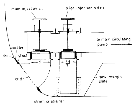
A doubler plate is welded to the skin (usually machined after welding); the chest flange is bedded to the doubler and studded in place. The joint is either spigot and jointing compound, or flat with a joint of canvas and red lead putty.
- The diameter of the bilge injection valve is at least ⅔ of the diameter of the main sea inlet.
- Valve spindles should be clear of the engine platform.
- Valves and operating gear require regular examination and greasing, with cleaning of strum or strainer.
2.5 Oil–water ballast chest
A standard fitting on most cargo vessels, on the double-bottom piping system. Normally all chests are open to oil fuel (bend) and blanked to water ballast. This means an error in opening the wrong valve would not in itself allow crossing of circuits. Alternatives: hollow one-way discharge plug cocks, or a system of interlock valves. Any system employed must prevent easy joining of oil and water circuits by accident.
2.6 Emergency bilge pump
See the suction and priming topic — a submersible centrifugal pump with its motor in an air bell, capable of working completely flooded, with a dc emergency circuit supply, also usable as an emergency fire pump.
3. Ballast System
The only real requirement is that there must be no possibility of sea or ballast water gaining access to dry cargo or adjacent compartments.
- Bilge connections to pumps connected to ballast or sea must be non-return valves or one-way cocks.
- Lock-up valves or blanks must prevent flooding or inadvertent pumping out of deep tanks.
- Water ballast and oil fuel must be effectively isolated.
4. Fire Main and Emergency Fire Pump
4.1 Starting the emergency fire pump
There are two methods of driving the emergency pump:
- By diesel — with reserve fuel for 3 hours.
- By an electric motor — with supply from the emergency switchboard.
Procedure:
Check the suction — is it fully open?
If the pump is of the self-priming type (with a vacuum pump), ensure the supply tank containing the priming water is full.
Close the discharge valve and open the air vent on the volute casing.
Close the vent once water starts coming out.
Start the pump and open the discharge valve gradually.
In the self-priming type, close the check valve on the attached vacuum pump line.
Monitor the pressure (suction and discharge) and the amperage of the pump.
Most of the time the emergency fire pump will work when the ship is loaded. But when the ship is in ballast condition, the emergency fire pump can lose suction. We have to make sure the vacuum pump runs properly; if it runs as desired, then water will fill the suction line.
4.2 Two-stage fire and general service pump
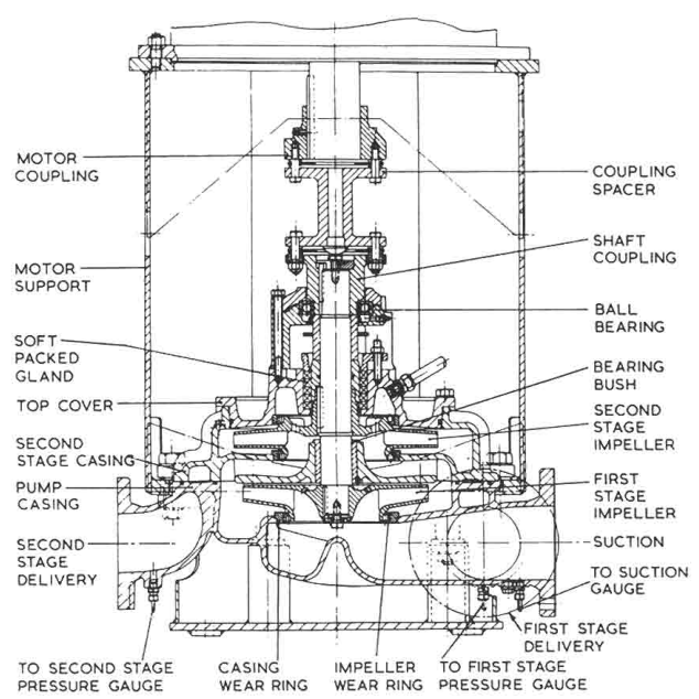
Because both low and high head are available from one pump, it can be used for double duty — lower head by pumping through the first stage impeller only, higher head through both impellers.
5. Sea Water Circulating System
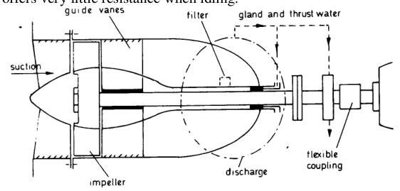
The axial flow pump is the classic main condenser circulating pump because:
- Under the low head (2.5–6.2 m) and high throughput (2800–9500 m³/h) conditions commonly required by main condensers, an axial flow pump with a higher speed than an equally matched centrifugal pump can be used, so the electric motor can be smaller.
- The pump will idle and offer little resistance when flow is induced through it by external means.
- The pump is reversible.
This combination makes it ideal for condenser circulating duties, especially in conjunction with a scoop injection, where the motion of the ship under normal steaming conditions is sufficient to induce flow through the idling pump and the condenser. Reversibility and high throughput make it ideal for heeling and trimming duties — an axial flow pump may be fitted on the straight transfer pipe between tanks installed for this purpose.
Materials: gunmetal casing for sea-water circulation; cast iron for heeling/trimming. Impellers aluminium-bronze, guide vanes gunmetal, shaft stainless steel with a renewable stainless steel sleeve in way of the bush. A water-cooled tilting-pad thrust bearing is required because of the considerable thrust generated. The mechanical seal is water-cooled, as is the composition shaft bush — the latter via a multi-leaf filter in condenser circulating service, because of the possible ingress of sand.
6. Cargo Pumping Systems
6.1 Crude oil tankers
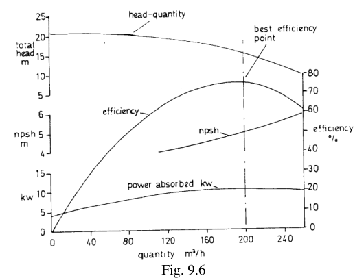
Reciprocating pumps were commonly used for cargo discharge and stripping before the advent of the VLCC. These have largely been replaced by centrifugal pumps, which have fewer wearing parts (no valves or linkages) and therefore require much less maintenance.
- The compact centrifugal pump can be mounted horizontally or vertically in the pump room, with turbine or electric motor drive from the machinery space.
- The drive shaft passes through the engine room bulkhead via a gas seal.
- Rate of pumping is high (typically 2600 m³/h) until a low level is reached, when loss of suction head and impeded flow through frames and limber holes makes a slowdown necessary — unless a small stripping pump is used (or a Vac-Strip system).
Centrifugal cargo pumps used differ according to cargo type:
- Product tankers (crude etc.): separate pump room with conventional centrifugal pumps, probably vertical overhung impeller, sometimes called barrel-type cargo pump. This double-eye inlet pump has either straight-through or 90° suction–discharge angle with pipe connections in the bottom half of the casing, and two external bearings above the impeller — the upper takes all the hydraulic thrust, the lower acts as a radial load bearing.
Advantages of this arrangement:
- Impeller can be sited lower in the pump room, improving suction conditions and reducing stripping time.
- Removal of the impeller without disturbing pipe joints.
- Easier access to bearings and shaft seal without removal of rotating elements.
6.2 Chemical, LPG and multi-product tankers
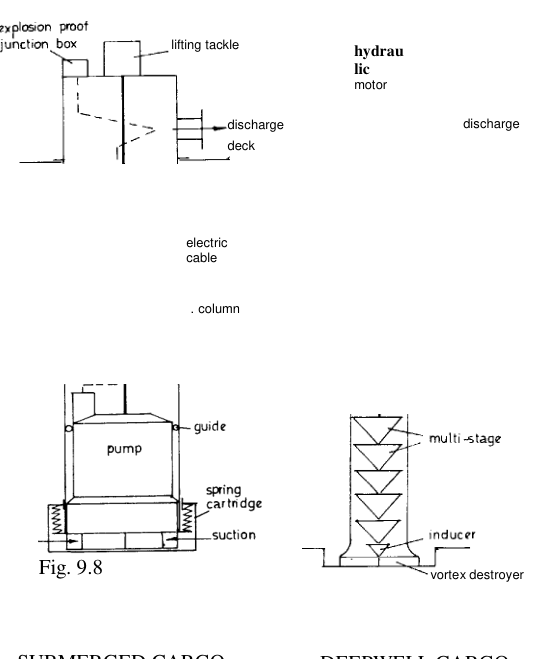
Here a separate pump is sited in each tank.
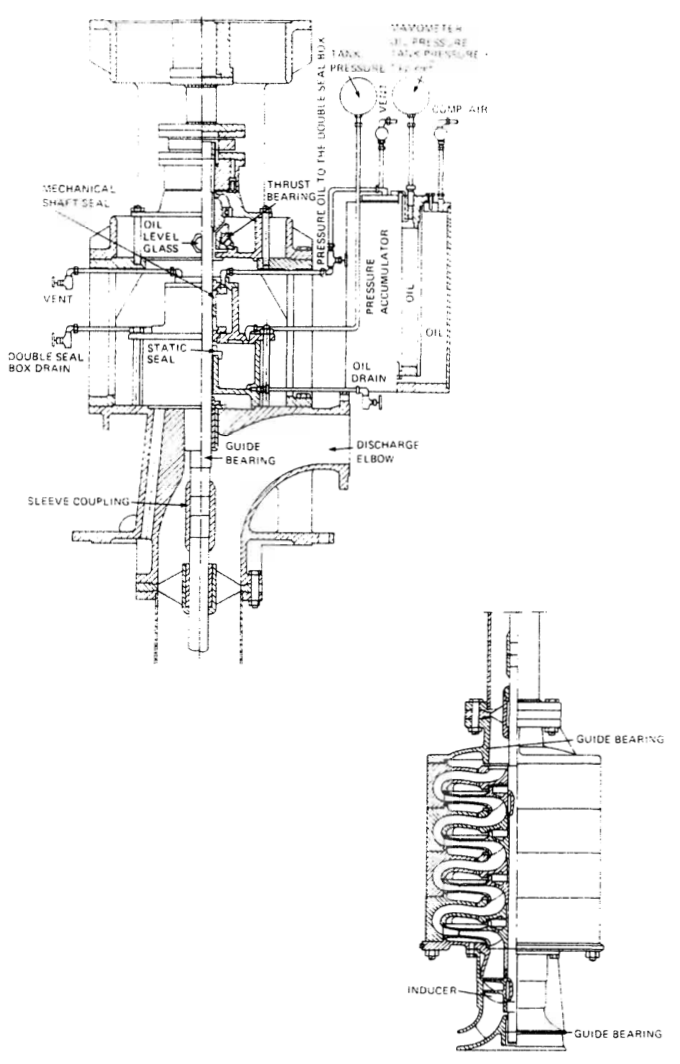
- Pumps driven through line shafting coupled to hydraulic motors on deck: deepwell, single or multi-stage with radial or mixed-flow impellers.
- Or submerged pumps electrically or hydraulically driven, usually single elements.
- The line-shaft pump, despite some bearing problems, is proving the more popular, especially for LPG carriers.
- Submersible pumps eliminate line-shaft bearings and gland problems, but expensive problems could occur due to hydraulic fluid leakage into the cargo and vice-versa.
The submerged electric motor driven pump rests on a spring cartridge which closes when the pump is raised, sealing off the tank from the column.
Air extraction is required on most pumps, especially on all bilge pumps. Early designs of circulating pumps employed a steam ejector on the volute casing together with a steam jet into the casing to condense and prime, or a direct water priming valve. Later designs incorporated a separate air pump.
In the more modern designs, reciprocating air pumps are usually replaced by rotary types. The usual suction separating chamber and ball float are provided, but the air connection from the top of the ball float chamber goes to a rotary air pump directly driven by an extension of the motor spindle on top of the pump. The rotor revolves in a specially shaped chamber supplied with fresh water from a reservoir in the air pump casing.
The rotor casing is continuously cooled by a closed water circuit from the pump discharge round the air pump jacket and back to the pump suction. The air pump can be placed in or out of operation by a control cock on the front of the air pump casing.
As the impeller vanes pass the suction port, air is drawn in and trapped between the water ring and the pump shaft. This "slug" of air is carried around and delivered to the discharge port — hence this pump is a positive displacement type.
6.3 Mixed-flow pumps for cryogenic carriers
A mixed-flow (part centrifugal, part axial) pump for cargo duty with cryogenic carriers may be fitted with a scroll (screw) type inducer to reduce the NPSH requirement and eliminate the need for a stripping pump. In practice two or more vertically arranged stages are used, operated by the prime mover on deck, with the bell mouth suction at the bottom of the tank and the pump casing acting as a long discharge pipe.
7. Fuel Oil Systems
The rules are lengthy but the engineer's instructions are worth knowing in full:
- A plan and description of the oil piping arrangement should be clearly displayed.
- Escape of oil heated to or above the flashpoint is most dangerous, and may result in explosion or fire.
- After lighting burners, the torches must be fully extinguished by the appliances provided.
- Cleanliness is essential to safety — no oil or other combustible substances should be allowed to accumulate in bilges, gutterways, tank tops or boiler flats.
- Before entering any oil tank which has contained oil fuel, the oil should be removed entirely and all oil vapour carefully removed by steaming and efficient ventilation. Tests of the atmosphere must be made to ensure safety before inspection or work begins.
Key installation requirements:
- Boiler, settling tank and oil fuel unit spaces must be clean, free of combustible material, and have good access.
- Oil tanks and oil pumps should be fitted as far from boilers as practicable, with trays and gutters.
- Filling stations should be isolated, well drained and ventilated.
- Every oil tank should have at least one air pipe, or a separate overflow pipe system (preferably returning to an overflow tank with visual and sight returns), with an aggregate area at least 1¼ times the aggregate area of the filling pipes.
- Oil units should be in duplicate, and any oil pump must be isolated to the oil system only, provided with a relief valve preferably on the suction side, capable of being shut down from a remote control position, and provided with shut-off isolating valves.
- Heating coil drains should be returned via an observation tank.
- Valves or cocks fitted to tanks in the machinery and boiler spaces should be capable of being operated from a remote position above the bulkhead deck.
- Ample ventilation and clearance spaces for circulation; no artificial lights capable of igniting oil vapour; ventilator dampers must have reliable operating gear clearly marked for shut and open positions.
8. Oily Water Separator and Bilge Discharge
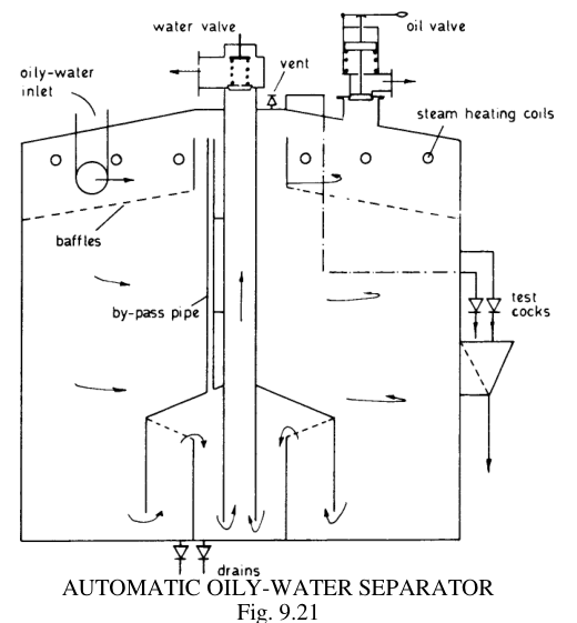
Bilge discharge overboard is permitted only when the ship:
- Is proceeding on passage;
- Is at least 12 nautical miles from land;
- Is not within a Special Area;
- Has an approved oily water separator or filtering system in operation;
- Has the oil content meter working and the alarm/auto-stop functioning.
In Special Areas (Mediterranean, Baltic, Black Sea, Red Sea, Persian Gulf area), bilge discharge is permitted only when an oily water separator or filtering system can achieve the required low oil content.
Typical automatic OWS operation:
- The oil content meter (OCM) is set at 15 ppm.
- If oil content is less than 15 ppm, the overboard valve opens and water discharges overboard.
- If oil content is more than 15 ppm, a 3-way solenoid valve activates to recirculate the water back to the bilge tank, both audio and visual alarms operate, and the water is not discharged to sea.
Pump-side implications:
- The OWS feed pump must be matched to the separator's capacity — starving or overfeeding both reduce separation efficiency.
- Coalescing-type separators are sensitive to detergents and emulsifiers in the bilge water; these must not be introduced.
- Record all overboard discharges in the Oil Record Book with the required detail.
9. Feed Water and Condensate Systems
The feed system is covered in the boiler notes; the pump-side points to remember:
- Feed pumps are multi-stage centrifugal (turbo-feed) for high pressure at moderate speed. Because the suction source is a deaerator at elevated temperature, the pump must be flooded — it can never be run in suction lift.
- Condensate extraction pumps take from the condenser under vacuum. The suction level is maintained constant by a float control where pumps are fed from deaerators or drain coolers.
- Air extraction is essential — a separate air pump (water-ring type, or steam jet air ejector) removes air from the condenser and from the pump suction, and maintains the vacuum.
- A closed feed system includes the air ejector, gland condenser/drain cooler, and feed heater; the extraction pump handles condensate from the condenser hotwell.
10. System Design Rules That Prevent Pump Problems
Never throttle the suction of any pump. Control on the discharge or by speed.
Fit a strainer on the suction, and maintain it. Record differential pressure.
Keep suction lines short, straight, and generously sized.
Avoid air pockets and loops in suction lines.
Ensure adequate submergence of suction bell mouths, or fit vortex destroyers.
Provide a relief valve on every positive displacement pump discharge, between pump and first isolating valve.
Provide a recirculation/minimum-flow line on centrifugal pumps that can be run at low flow.
Provide a non-return valve on the discharge of every pump discharging into a common main or against a head.
Isolate incompatible circuits — oil/water, bilge/ballast, cargo/ballast — with blanks, lock-ups or interlock valves.
Support the piping — inadequately supported piping causes vibration and coupling misalignment, and is a listed cause of pump vibration.
Ensure the pump is not the system's weak point — check that the pump's duty point actually lies on the installed system curve.