Pump Principles and Pump Types
A pump does not create flow — it adds energy, and the system decides how much of it becomes flow.
Key Principles at a Glance 5 points
- A pump imparts energy to a fluid; it does not create flow. The system — pipes, static lift and tank pressures — decides how much energy becomes flow.
- Most pump failures are suction-side failures, not pump-body failures.
- Two families decide the rules: positive displacement (self-priming, relief valve essential, discharge open on start) and roto-dynamic (must be primed, no relief valve needed, discharge throttled on start).
- A centrifugal pump contains no liquid initially is like a pump with an essential part missing — the liquid is a working part of the pump.
- Centrifugal overloads at low head and high throughput; a positive displacement pump started against a closed discharge destroys itself or its relief valve.
1. What a Pump Actually Does
A pump is a device that imparts energy to a fluid. It does not create flow by itself — it adds energy to the liquid, and the system (the pipes, the static lift, the tank pressures) decides how much of that energy is converted into flow.
Onboard, pumps serve the main propulsion plant, the generating plant, the auxiliary boiler plant, the cargo plant, and every auxiliary system. Pump failure can shut down the entire plant. Correct functioning and maintenance of pumps and pumping systems is therefore of paramount importance.
The engineer's mental model is simple and it holds for every pump type:
Suction side: can the pump get liquid into it? Energy transfer: how does it add pressure or velocity energy? Discharge side: what does the system resistance allow through? Almost every pump problem traces back to the first question.
Most pump failures are suction-side failures, not pump-body failures. Keep that in mind throughout these notes.
2. The Two Families — and Why the Difference Matters
Every pump onboard belongs to one of two families. The difference is not academic — it decides priming, relief-valve requirements, discharge-valve operation, and what happens when you shut the discharge.
2.1 Positive displacement pumps
One or more chambers are alternately filled and then emptied. This covers reciprocating, screw, gear and water-ring types.
- They do not require a priming device — in fact they may be used as priming devices.
- Used for small to medium discharge rates.
- Can pump fluids over a wide range of viscosity.
- Can develop high pressure differentials (especially reciprocating).
2.2 Dynamic pressure pumps (roto-dynamic)
A tangential acceleration is imparted to the fluid. This covers centrifugal, axial and mixed-flow types (mixed flow is part axial, part centrifugal).
- Depending on supply head they may require a positive displacement pump as a priming device.
- Used for medium to high discharge rates.
- Usually confined to low viscosity fluids.
- Generate only low to moderate pressure differentials.
2.3 The operational consequences
| Feature | Positive displacement | Centrifugal / roto-dynamic |
|---|---|---|
| Priming | Self-priming | Must be primed (or have a priming device) |
| Relief valve | Essential in discharge line | Not essential (power drops as discharge closes) |
| Discharge valve on start | Must be open (or bypass open) | Must be closed/throttled on start |
| Effect of closing discharge | Pressure rises until something breaks | Pressure rises moderately; power drops |
| Flow control | Speed, bypass, or stroke | Throttling, speed (VFD), impeller trim |
| Viscosity | Wide range | Low viscosity only |
| Flow character | Pulsating (needs air vessel) | Steady |
The last row of the table is the one that gets engineers into trouble. A centrifugal pump started with the discharge valve wide open can overload its motor at low head and high throughput; a positive displacement pump started with the discharge closed will destroy itself or its relief valve.
Centrifugal: discharge throttled — the motor is not overloaded at shut-off. Positive displacement: discharge open — closed discharge means pressure rises until something breaks.
3. Centrifugal Pumps — the Working Principle
Rotation of the impeller causes the liquid it contains to move outwards from the centre to beyond the circumference of the impeller. The revolving liquid is impelled by centrifugal effect. It can only be projected into the casing around the periphery if other liquid in the casing can be displaced; the displaced liquid moving from casing to delivery pipe causes flow in the discharge side of the system.
The liquid in the impeller and casing is essential to the operation. In moving out under centrifugal effect it drops the pressure at the centre, to which the suction pipe delivers the liquid to be pumped. The moving liquid acts in the same way as a reciprocating pump piston on its suction stroke. Provided the pump is filled initially with liquid and flow is maintained, the suction stroke action continues. If such a pump contains no liquid initially, it is as though an essential part is missing.
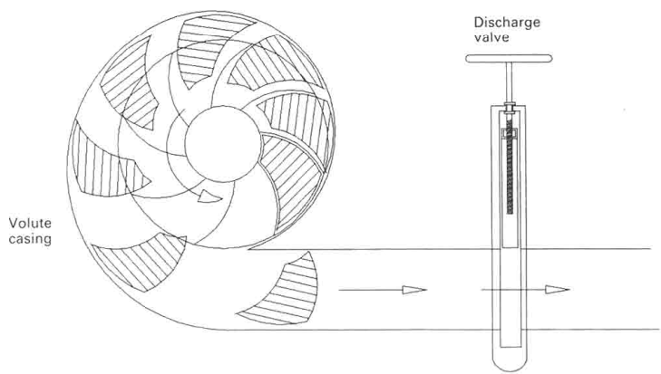
That single paragraph explains priming, cavitation, and why a centrifugal pump cannot pump gas — all three are consequences of "the liquid is a working part of the pump."
4. Pump Types and Where Each Is Used
4.1 Centrifugal — the general workhorse
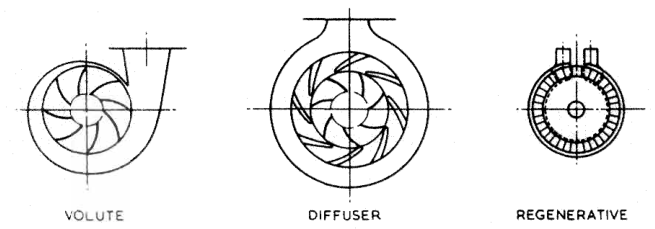
- Volute pump: spiral casing gradually reduces velocity after the impeller, converting kinetic to pressure energy. General purpose; the commonest design.
- Diffuser (turbine) pump: a ring of stationary guide passages around the impeller converts a larger amount of kinetic energy to pressure. Used for high pressure, as in multi-stage boiler feed pumps.
- Regenerative pump: relatively high pressure, small capacity.
- Multi-stage: fluid from one impeller is led to the eye of the next, so total head = head per stage × number of stages. Used for high pressure at moderate speed (turbo-feed).
- Double-inlet (double eye): fluid enters from two sides, giving twice the discharge at a given head. Used for low NPSH applications.
4.2 Axial flow
Best where large capacity and wide variation of low lift head at constant speed are required. Efficient, simple, wide capacity range. Can be made reversible, and offers very little resistance when idling — which is exactly why it is ideal for condenser circulating duties with scoop injection, and for heeling and trimming duties.
4.3 Reciprocating
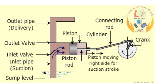
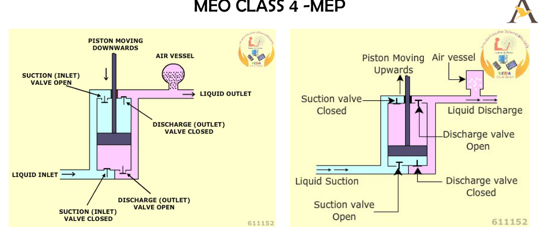
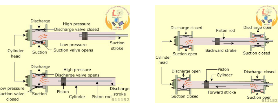
During the suction stroke the piston moves and creates a vacuum in the cylinder; the suction valve opens and water enters. During the delivery stroke the increasing pressure closes the suction valve and opens the delivery valve.
- Air vessels on suction and discharge act as buffers, damping pressure fluctuations. As discharge pressure rises, air in the vessel compresses; as pressure falls it expands, returning stored energy to the system.
- A relief valve is always fitted between suction and discharge chambers to protect the pump if operated with a closed discharge valve.
- Classified as: direct or indirect acting; simplex or duplex; single or double acting; high or low pressure; vertical or horizontal.
Advantages: high outlet pressure, high suction lift, priming not required.
Disadvantages: high wear and tear; non-uniform flow; low flow rate; heavy and bulky; high initial cost.
Uses: lubricating oil pump to the main engine; main bilge suction pump; vertical duplex bilge and stripping pumps.
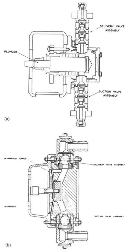
In a direct-acting pump the pump rod is a direct extension of the piston rod. In an indirect-acting pump there is an intermediate mechanism (lever, cam, or rotating crankshaft) between piston and plunger, allowing relative stroke length or speed to be changed.
The differential-area principle: the steam piston is larger in diameter than the plunger. Since F = p × A, the same steam pressure acting on a larger area produces a much higher pressure on the smaller plunger area. A high-pressure pump therefore discharges a small volume against high pressure; a low-pressure pump may have a steam piston smaller than the plunger.
4.4 Gear pumps
A rotary positive displacement pump. In a twin gear pump one gear is connected to the motor and drives the other; the drive and driven shafts rotate in opposite directions. The fluid is carried round between the teeth and the casing. There are no suction or discharge valves.
Fairly efficient and smooth running; best suited to pumping oil, particularly boiler oil fuel pressure feed.
4.5 Screw pumps
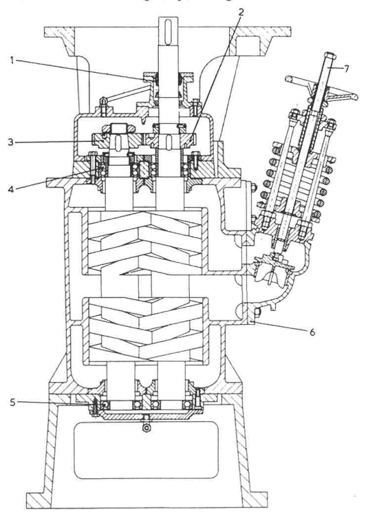
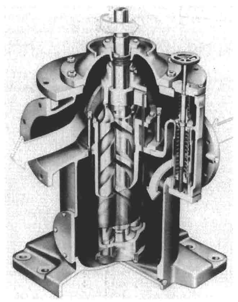
Fluid enters the outer suction manifolds and passes through the meshing screws to the central discharge manifold. Quiet and reliable, particularly suited to pumping oil.
- Self-priming, and can deal with large volumes of air while running smoothly and maintaining discharge pressure — ideal for tank draining and intermittent supply such as lubricating oil systems with the vessel rolling.
- Timing gears fitted to some designs maintain correct clearance between screws, preventing overheating and seizure. Modern screw profiles preclude timing gears, eliminating turbulence and vibration.
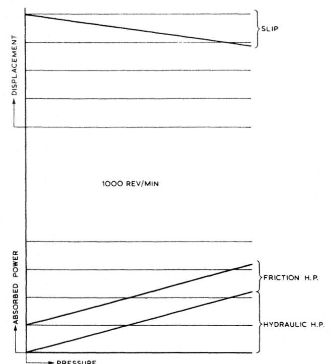
- Always provided with a relief valve bypassing back to suction.
- Triple-screw pumps: the centre screw is driven; the two outer screws are driven by fluid pressure and act purely as seals. Works well at high pressure and high viscosity (up to 4000 cSt).
4.6 Axial flow vs centrifugal — the comparison that matters
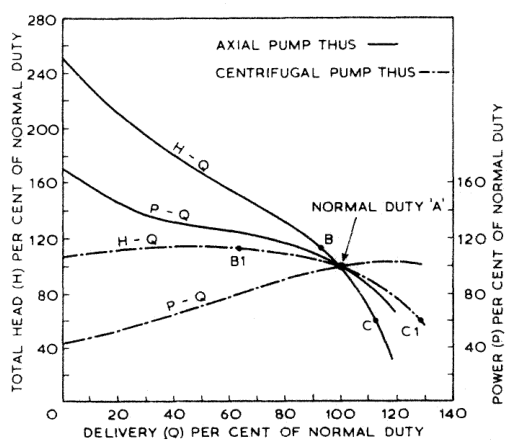
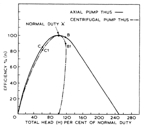
Reading these two curves answers several standard oral questions at once:
- Closing the discharge of a centrifugal pump: pressure rises by a moderate amount and power demand actually drops. The motor is not overloaded at shut-off.
- Centrifugal pump at low head / high throughput: absorbed power rises. The motor can be overloaded at low head and high throughput — the opposite condition for overload of an axial pump.
- The axial pump retains reasonable efficiency over a wider head range than the centrifugal pump.
- The axial pump will idle with little resistance when flow is induced through it externally, and it is reversible.
4.7 Special-duty centrifugal designs
- Vertical turbine pumps: impellers discharge into a diffuser bell rather than a volute. Don't need priming — impellers and bell housings are submerged. Head varied by adding stages. Used for wells, rivers, tanks and sumps, and as in-line boosters.
- Non-metallic pumps: wet end lined/coated with epoxy resin, PTFE, phenolic resin, rubber, polyester, glass, ceramic, plastic or carbon/graphite. Used for abrasive, chemically corrosive and oxidizing liquids. Mostly back-pullout construction.
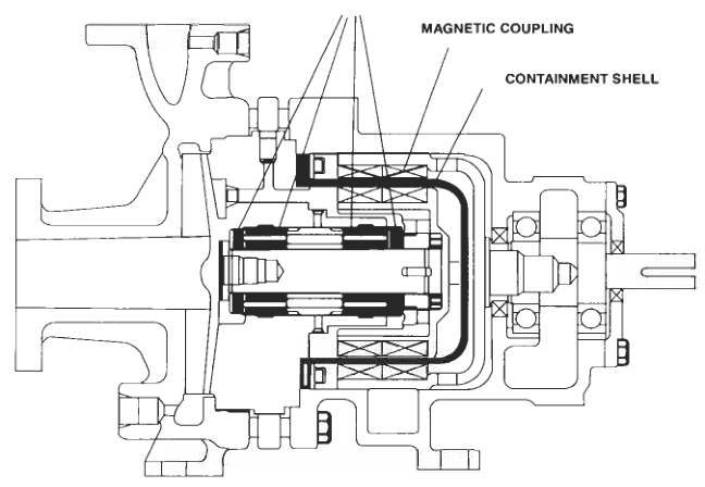
- Magnetic drive pumps: a conventional motor drives one set of magnets which drive magnets fixed to the pump shaft; a non-magnetic housing isolates the pumped liquid. No mechanical seal. Cannot run dry, cannot resist extended cavitation, must run close to BEP, magnets can decouple, and they tend to heat the pumped liquid.
- Canned motor pumps: the motor rotor is hermetically sealed inside a can and runs wet in the pumped liquid. No mechanical seal, only two bearings. Cannot run dry or under cavitation, fine abrasives will damage the bearings.
5. Impeller Geometry — the Vocabulary
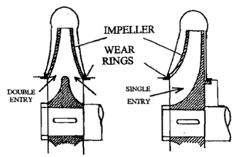
- Single entry — suction from one side only. A stationary wear ring is fitted behind the rear shroud to take up thrust.
- Double entry — suction from both sides. Gives twice the discharge at a given head; halves the NPSHr; balances axial thrust. Used for low-NPSH applications.
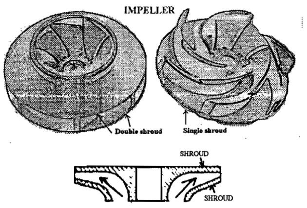
- Open impeller — vanes not enclosed by shrouds; the casing effectively shrouds the vanes. Good for dirty liquids, but higher leakage.
- Semi-open (semi-enclosed) — one shroud only.
- Totally enclosed (double shrouded) — both shrouds; the most efficient, but unsuitable for solids.
Impeller classification is done by specific speed, Ns — see the performance topic. Radial-vane impellers (Ns 500–1500) generate head by pure centrifugal action; Francis/mixed-vane (Ns 1500–7000) generate head by a mixture of centrifugal action and impeller design; axial-flow impellers (Ns above 7000–8000) are for high flow with little head.
6. Where Each Pump Type Is Used Onboard
| Service | Usual pump type |
|---|---|
| Sea water circulating (main condenser) | Axial flow (reversible, scoop-assisted) |
| Boiler feed | Multi-stage centrifugal / diffuser (turbo-feed) |
| Condensate extraction | Multi-stage centrifugal |
| General service, salt/fresh water, bilge, ballast | Single-entry centrifugal |
| Fire and general service (two-stage) | Centrifugal, two-stage |
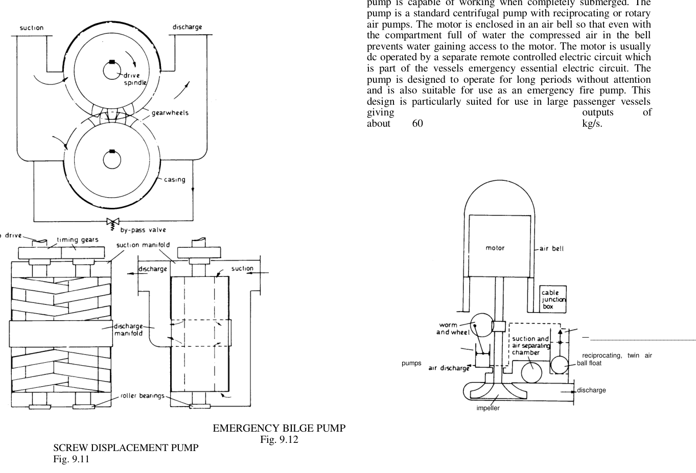
| Emergency fire pump | Centrifugal, submersible motor in air bell |
| Main engine lubricating oil | Reciprocating or screw |
| Boiler fuel oil pressure feed | Gear pump |
| Fuel oil transfer / booster | Screw or gear |
| Cargo discharge (crude) | Large centrifugal, vertical overhung (barrel) |
| Cargo (chemical / LPG / multi-product) | Deepwell line-shaft or submerged |
| Cargo stripping / tank draining | Screw (self-priming) or reciprocating |
| Bilge and stripping (small vessel) | Vertical duplex reciprocating |
| Steering gear hydraulic | Variable-delivery axial piston / Hele-Shaw |
| Priming (all centrifugal) | Water-ring / liquid-ring exhauster |
| Metering / dosing | Plunger metering pump |