
Suction, NPSH, Cavitation and Priming
Discharge-side problems are usually obvious and recoverable; suction-side problems are subtle, damaging, and often diagnosed too late.
Key Principles at a Glance 5 points
- All the pump production is based on the suction pressure — every pump needs a gauge at the suction nozzle.
- Head is the constant, pressure is not: a pump generating 125 ft of head reads 54.1 psig on water but 37.8 psig on gasoline. You cannot specify a pump by psi.
- NPSHa must always exceed NPSHr. If NPSHa falls below NPSHr, the pump cavitates.
- Above about 94 °C water must be supplied from a head, which is why hot feed water systems always place the pump below the de-aerator.
- A centrifugal pump cannot pump a gas — before start-up the casing must be filled with liquid and vented of all gases.
1. Why the Suction Side Is the Vulnerable Side
Discharge-side problems are usually obvious and recoverable; suction-side problems are subtle, damaging, and often diagnosed too late.
The pump can only convert the pressure it receives at the suction nozzle into discharge pressure. All the pump's production is based on the suction pressure. If the suction pressure is inadequate, it leads to cavitation. Because of this, all pumps need a gauge at the suction nozzle to measure the pressure entering the pump.
Three pressures matter inside a pump:
- Suction pressure — at the pump suction nozzle. Probably the most important pressure inside the pump.
- Discharge pressure — suction pressure plus the total pressure developed by the pump.
- Seal chamber pressure — the pressure in the stuffing box/seal chamber to be sealed. Must be within the mechanical seal's limits.
1.1 Head versus pressure — the concept that causes most confusion
The maintenance technician reads gauges in psi; the manufacturer talks in head. Head is the constant: a pump that generates 90 ft of head can elevate water, gasoline, caustic soda or any liquid to a height of 90 ft. The psi reading depends on the conversion factor 2.31 and the specific gravity.
This is why you cannot specify a pump by psi. A pump generating 125 ft of head produces:
| Liquid | sp.gr. | Pressure |
|---|---|---|
| Water | 1.0 | 54.1 psig |
| Gasoline | 0.70 | 37.8 psig |
| Sea water | 1.03 | 55.7 psig |
| Conc. sulfuric acid | 2.00 | 108.2 psig |
Same pump, same head, same rpm — wildly different gauge readings. Conversely, three pumps developing the same discharge pressure will develop different heads inversely proportional to specific gravity.
2. Suction Lift — the Theoretical Limit and the Practical Limit
Consider a reciprocating pump. If it could create a perfect vacuum in the barrel, it should theoretically lift cold fresh water from 10.3 m above the suction valve.
So pump lift depends on:
- The barometer reading (the vacuum attainable).
- The fluid pumped — oil with density below 1.0 can be lifted a greater amount.
- The fluid temperature — warm fluids tend to vaporise and destroy the vacuum.
In practice a good reciprocating pump will lift cold water from about 8 m with a high barometer. As the fluid temperature rises, suction lift decreases:
| Temperature | Practical lift (760 mm barometer) |
|---|---|
| Cold water | 7.5 m (750 mm barometer) |
| 64 °C | 3 m |
| 77 °C | 2.1 m |
| 94 °C | 0 m — the pump will not draw water |
| 110 °C | Head required: 3 m |
| 123 °C | Head required: 6.7 m |
Above about 94 °C, water must be supplied from a head to increase the pressure on the suction valve and prevent vapour lock. This is why hot feed water systems are always arranged with the pump below the de-aerator.
2.1 Practical lift by pump type
| Pump type | Practical cold-water lift (high barometer) |
|---|---|
| Reciprocating | ~8 m |
| Centrifugal (facing clearances of a few mm) | ~7.3 m |
| Gear / screw displacement (750 mm barometer) | ~6.7 m |
Centrifugal pumps are more limited because clearances in a fast-running centrifugal pump are difficult to maintain. They are also very prone to cavitation, especially at inlet to the impellers.
3. NPSH — Net Positive Suction Head
NPSH is a measure of the pump suction conditions. There are two values and they must be compared:
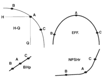
- NPSHr (required) — a property of the pump. The minimum suction head the pump needs to avoid cavitation. Published by the manufacturer as a curve of NPSHr against capacity.
- NPSHa (available) — a property of the system. What the installation actually provides.
3.1 The NPSHa formula
Where:
| Term | Meaning |
|---|---|
| Ha | Atmospheric head — read from a barometer/table; reduced at altitude |
| Hs | Static head — the static height in feet observed from the suction liquid surface to the pump centreline. Positive if the liquid level is above the pump; negative if the pump is in suction lift. |
| Hvp | Vapour pressure head — depends on the liquid and its temperature. Rises with temperature. |
| Hf | Friction head — losses in suction piping, valves and fittings |
| Hi | Inlet head — a safety factor, typically 2 ft |
3.2 How to increase NPSHa — the practical list
For a pump in suction lift (negative Hs):
Raise the liquid level in the suction vessel — increases Hs.
Elevate the suction vessel — increases Hs.
Lower the pump — increases Hs.
Lower the temperature of the fluid in the suction vessel — reduces Hvp.
Pressurise the suction vessel with air or a gas compatible with the liquid — increases the artificial Ha.
Reduce the losses (Hf) of connections and fittings in the suction line.
Eliminate some elbows. If the suction piping has multiple elbows, straighten it.
Increase the suction pipe diameter — reduces velocity and friction.
Convert to a pump with a double suction impeller — double suction impellers are for low NPSH applications.
Use two smaller pumps in parallel.
Use a larger/slower pump.
Turn off the pump and drain the tank by gravity.
3.3 Suction specific speed (Nss)
An index used to describe the suction geometry of the impeller. It uses NPSHr in the denominator:
Where N = pump/motor speed in rpm, Q = flow at BEP in gpm, NPSHr = required NPSH at BEP.
4. Cavitation
4.1 The mechanism
Low pressure regions occur in the flow at points where high local velocities exist. If vaporisation occurs due to these low pressure areas, bubbles occur. These expand as they move with the flow and collapse when they reach a high pressure region.
The formation and collapse of bubbles is very rapid, and collapse near a surface generates very high pressure hammer blows, resulting in:
- Pitting
- Noise
- Vibration
- Fall-off in pump efficiency
4.2 Why centrifugal pumps are especially prone
During operation, if the drop in pressure created at the suction side of a centrifugal pump (by liquid moving radially outwards from the eye of the impeller) is greater than the vapour pressure for the temperature of the liquid being pumped, then vapour will be drawn from the liquid in this area.
This is likely to occur if:
- There is a restriction in the suction pipe.
- The liquid is volatile or at a higher temperature than anticipated.
- The impeller speed is excessive.
A vapour cavity of this type is likely to cause loss of suction or erratic operation.
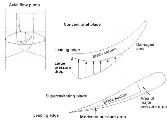
A lesser cavitation problem occurs when NPSHr is only just matched by NPSHa, because centrifugal pumps have features which promote localized cavitation: the impeller entry on the side away from the shaft has a hydrofoil-like profile, and local liquid flow creates a pressure drop starting at the effective leading edge and extending along the surface. A vapour pocket created by that pressure drop collapses in a higher-pressure area and causes damage. A change of flow direction from axial to radial also makes the fluid experience different velocities.
4.3 The recognised types of cavitation
There are five recognised types: vaporization, turbulence, internal re-circulation, vane passing syndrome, and air aspiration.
- Incipient cavitation (just beginning) can occur when suction lift capability cannot meet supply requirements and the output reduces until the two coincide. Under these conditions the pump runs noisily and cavitation damage can occur. By throttling the discharge, or reducing pump speed, rough running and possible damage can be avoided.
- Super cavitation occurs when the vapour bubbles collapse within the liquid after the impeller.
4.4 Diagnosing cavitation
Signs:
- Crackling, gravel-like noise from the casing.
- Erratic flow and pressure, especially on load change.
- Vibration.
- Progressive loss of head and capacity.
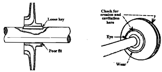
- On dismantling: impeller vane metal removed in a spongy, honeycombed pattern, typically on the suction side of the vanes and near the eye.
Distinguish liquid knock from mechanical knock in reciprocating pumps — they sound similar but have completely different causes (liquid knock = cavitation/air; mechanical knock = loose piston, worn bearings, loose crosshead pins).
4.5 What to do about cavitation
- Lower the temperature — reduces Hvp.
- Raise the liquid level in the suction vessel — elevates Hs.
- Change the pump (e.g. to a double-suction or lower-Nss design).
- Reduce the suction lift.
- Reduce pump speed or throttle the discharge slightly.
- Clean the suction strainer and check the suction line for obstructions.
- Check for air ingress at the suction side (see the air-ingress section).
4.6 Inducers and supercavitating pumps
Inducers are sometimes fitted to centrifugal pump impeller shafts at suction. Their purpose is to ensure the fluid supplied to the impeller is at sufficient pressure to avoid cavitation at impeller suction, or to enable the pump to operate with a lower net positive suction head. Types: scroll, screw or propeller.
The propeller inducer (like a stub-bladed fan) is fitted to supercavitating pumps, where cavitation occurs between the inducer and the impeller. Such pumps can operate at about one third of the NPSH normally required for conventional centrifugal pumps, and are suitable for LPG and LNG carriers.
Supercavitating axial pump blades have a wedge cross-section to produce a different cavitation pattern: the pressure drop is not pronounced at the leading edge, is minimal over the full suction side, and is exaggerated only at the trailing edge. Vapour pockets persist until clear of the blade and collapse where they cause no damage. They operate at high speed but generate low discharge head. Used as suction boosters or inducers for conventional centrifugal cargo pumps in liquefied gas carriers because they can handle liquids at or near their vapour pressure at higher speeds than conventional pumps.
5. Air Ingress — the Other Way to Lose Suction
Air entering the suction side destroys the pump's ability to draw liquid just as effectively as cavitation, but it is a mechanical fault, not a thermodynamic one.
5.1 Where air gets in
- Through loose flange faces and gaskets on the suction side.
- From bubbles and air pockets carried in the liquid.
- From products that foam.
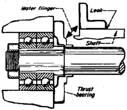
- Through a leaking shaft gland.
- Through an open valve on an empty bilge or an uncovered suction.
- Through vortexing at the suction inlet when the tank level is low.
5.2 What to do about it
- Tighten all flange faces and gaskets.
- Raise the level in the suction vessel, or elevate the vessel, or lower the pump (increases Hs).
- Lower the temperature of the fluid in the suction vessel.
- Pressurise the suction vessel.
- Fit or repair vortex destroyers at the suction bell mouth.
- Renew gland packing or the mechanical seal.
- Check the submergence of the suction pipe — see the priming section.
6. Priming — Why, and How
A centrifugal pump cannot pump a gas. Therefore the differential pressure necessary for flow will not be created if the impeller is handling air or vapour. Prior to start-up, the pump's casing should be filled with liquid and vented of all gases.
6.1 The priming options
- Gravity / flooded suction — the pump is placed below the level of the liquid to be pumped, so it floods if valves are opened.
- Central priming system — the pump is connected through vents to a central system fitted with vacuum pumps or air ejectors. Generally used to prime multiple pumps on the vessel.
- Integral or independent vacuum pump — fitted to the individual pump.
- Self-priming centrifugal pump — a special design, typically fitted with a suction chamber.
- Positive displacement pump as a primer — because PD pumps are self-priming and can handle large volumes of air.
6.2 Water-ring (liquid-ring) primers
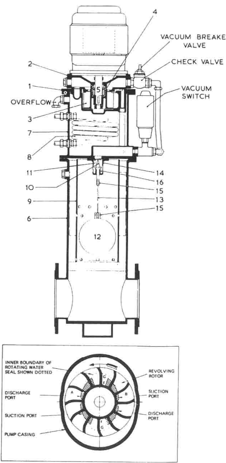
The removal of air from pump suction pipes is usually achieved with a liquid ring primer, necessary to produce vacuum conditions so that atmospheric pressure on the liquid surface promotes flow into and priming of the pump.
The liquid ring air pump consists of a bladed circular rotor, shrouded on the underside, rotating in an oval casing. Sealing water is drawn into the oval casing through a make-up supply pipe. The water, thrown out to the casing periphery by the turning rotor, whirls around to form a moving layer against the oval casing. The water seals the rotor blades and recedes from and re-approaches the rotor boss twice in each revolution. The effect is to produce a series of reciprocating water pistons between the blades.
As the water surface moves out from the rotor boss it provides a suction stroke; as it moves in, a discharge stroke. The shaped suction and discharge ports permit air to be drawn in from the main pump suction pipe float chamber and expelled to atmosphere.
- A continuous supply of sealing water is circulated from the primer reservoir to the whirlpool casing and discharged with the air back to the reservoir. The air passes to atmosphere through the overflow pipe.
- A cooling coil in the reservoir limits the temperature rise of the sealing water during long periods of operation. Supply can be taken from any convenient sea-water connection — about 0.152 litres/s at a pressure not exceeding 2 bar.
- Air handling capacity is good — air gulps are quickly cleared and small air leakages are handled without any fall in pump performance.
This type replaced the now-obsolete reciprocating pump primers. Eccentric vane primers have good air handling capability but vanes wear and sometimes jam in the rotor slots. Ejectors are effective if sized correctly but their efficiency is low.
6.3 The float chamber
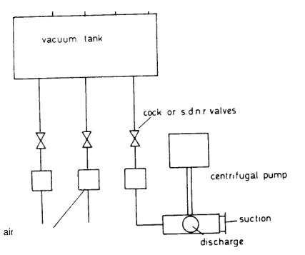
The water ring primer draws air from the pump suction pipe through a float chamber. The float rises as liquid replaces air; as the level rises well above the pump, the impeller and casing are flooded and the float spindle closes off the suction. This ensures the primer itself is not flooded.
6.4 Central priming systems
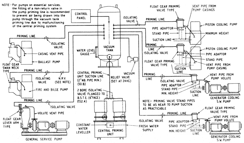
Used when more than four pumps require priming facilities. It gives a large air-exhausting reservoir as well as capacity greater than individual pumps can carry. Pump casings can be filled with liquid before starting. The air exhausting units are usually of the liquid ring type.
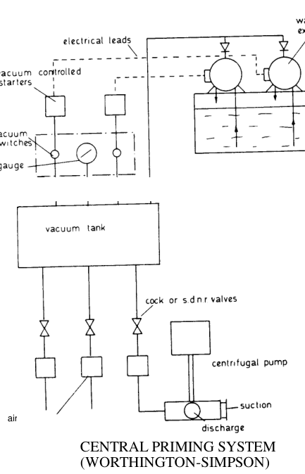
Operation: water ring exhausters maintain a vacuum condition between pre-set limits in the vacuum tank. Opening the priming cock (or s.d.n.r. valve) for a pump causes priming to take place. To prevent water entering the vacuum tank after priming, float operated air release valves automatically close.
For essential services an s.d.n.r. (screw-down non-return) valve is fitted instead of a priming cock, so that if the valve is inadvertently left open and the vacuum in the tank is lost, air is not drawn into the pump and its suction is not lost with possible serious consequences to plant.
Advantages of the central priming system:
- Saving in total power — each pump does not have its own exhauster running all the while the pump operates.
- Reduced capital cost.
- Simplified maintenance.
- Automatic — takes care of any minor leaks present in the suction side of a centrifugal pump.
Two water ring exhausters are mounted on top of a water supply tank; one acts as standby, but both can operate together under heavy demand.
6.5 Priming practice onboard
For a self-priming type with an attached vacuum pump:
Ensure the supply tank containing the priming water is full.
Close the discharge valve and open the air vent on the volute casing.
Close the vent once water starts coming out.
Start the pump and open the discharge valve gradually.
Close the check valve on the attached vacuum pump line.
Monitor suction and discharge pressure, and motor amperage.
6.6 Loss of prime at low tank level — and the Vac-Strip answer
A centrifugal pump will not regain lost suction until the pump fills with liquid after the vapour is released. In crude oil cargo discharge, as the tank level falls:
- Entrained air increases, and gassed oils release volatile light fractions if the suction pipe pressure falls below the oil's vapour pressure.
- Flow through frames and limber holes is impeded.
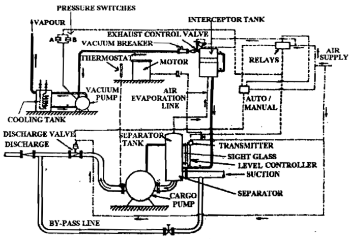
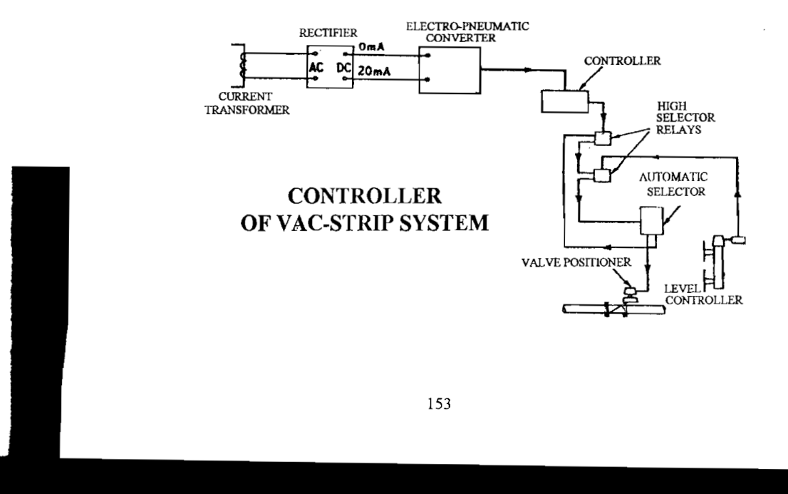
This forces a slowdown in the rate of pumping unless a small stripping pump is used. Systems such as the Worthington-Simpson 'Vac-Strip' enable a faster general rate of discharge to be maintained while reducing the rate temporarily at low level. A separator with a vapour outlet, sight glass and level controller is placed in the suction line near the pump; the vapour outlet leads to an interceptor tank with a moisture eliminator, and thence to a water-ring vapour extraction pump controlled by pressure switches. Small quantities of liquid carried with the vapour drop out and return to the pump. This arrangement ensures the pump is always fully primed.
7. Suction Piping Design — the Rules That Prevent Most Problems
- Suction pipe as short and as straight as possible.
- Avoid loops in the suction line where air can collect.
- Avoid multiple elbows. Each elbow adds Hf and creates turbulence.
- Suction pipe diameter generous — sized for low velocity, not for economy.
- No reducing pipes immediately at the suction flange unless the maker specifies; use an eccentric reducer with the flat side up so air cannot pocket.
- Ensure adequate submergence of the suction bell mouth to prevent vortexing.
- Fit a strainer/mud box — and clean it.
- Suction valve fully open before starting.
- Pump should be sited as low as possible, below the liquid level where practicable.
A slow rate of discharge by a centrifugal cargo pump can be explained by increasing head due to a restricted or very long discharge pipe, high viscosity of the liquid, discharge to a storage tank sited at a high level, or even a partly open valve on the discharge line.
8. Emergency Bilge Pump — the Submersible Case
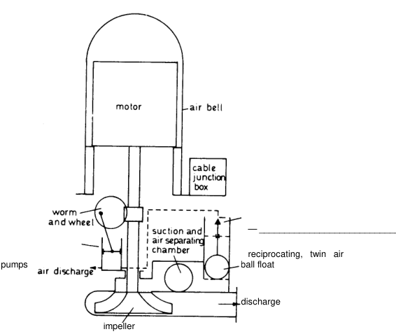
The function of this pump is to drain compartments adjacent to a damaged (holed) compartment. It is capable of working when completely submerged.
- It is a standard centrifugal pump with reciprocating or rotary air pumps for priming.
- The motor is enclosed in an air bell, so that even with the compartment full of water the compressed air in the bell prevents water reaching the motor.
- The motor is usually dc operated by a separate remote-controlled electric circuit which is part of the vessel's emergency essential electric circuit.
- Designed to operate for long periods without attention; also suitable for use as an emergency fire pump.
- Particularly suited to large passenger vessels, giving outputs of about 60 kg/s.