

Piston Crowns, Piston Rings & Thermal Mechanics
Master marine diesel pistons: Cr-Mo crown metallurgy, cocktail shaker cooling, CPR rings, butt clearances, groove wear, and ring sticking prevention.
1. Piston Crown Construction, Metallurgy & Inconel Cladding
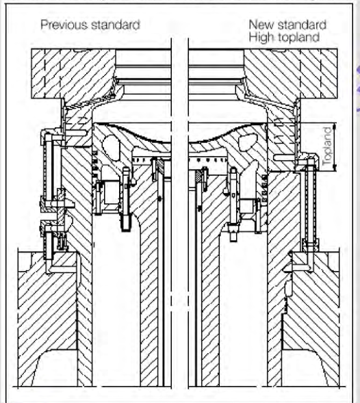
The marine diesel engine piston crown operates in the most punishing thermal and mechanical environment of any moving machinery component. It forms the moving lower boundary of the combustion chamber, enduring cyclic mechanical firing pressures up to 210 bar alternating with scavenge pressures, while its upper gas face is bathed in combustion flame reaching 1800°C to 2000°C.
Design Requirements & The Thermal Paradox
Engineering a large-bore (500 to 980 mm diameter) crosshead piston requires resolving two fundamentally conflicting engineering demands:
- Mechanical Strength: The crown must possess sufficient thickness and tensile fatigue strength at elevated temperatures to withstand millions of cycles of fluctuating gas bending loads without cracking.
- Thermal Conductivity: The crown must transfer heat rapidly away from the combustion surface into internal cooling passages. Increasing metal thickness impedes heat flow, creating a steep thermal gradient (ΔT ≈ 250°C–300°C) between the gas face and the cooling oil side that generates severe compressive thermal hoop stresses.
Crown Metallurgy & Inconel Cladding
Modern two-stroke piston crowns are forged or cast from high-grade Chrome-Molybdenum alloy steel (typically 0.5% Mo, 1.0%–1.5% Cr, with trace Vanadium).
- Role of Alloying Elements: Molybdenum maintains high creep resistance and hot tensile strength at 450°C, while chromium provides oxidation resistance.
- Inconel 625 Cladding: In heavy fuel oil combustion, the combination of vanadium and sodium forms molten vanadate slags that melt at ~535°C, causing catastrophic hot corrosion and "burning away" of bare steel crown rims. To counteract this, modern crowns have a 6 to 8 mm thick layer of Inconel 625 (a nickel-chromium-molybdenum superalloy) laser-clad or submerged-arc welded across the outer rim and bowl. Inconel is virtually immune to vanadium pentoxide attack.
- Chrome-Plated Ring Grooves: Because the piston crown expands more than the cast iron rings, relative sliding causes severe micro-fretting and adhesive wear of the ring lands. Ring groove upper and lower seating faces are electroplated with 0.3 to 0.5 mm of hard industrial chrome (or induction hardened) to eliminate groove wear and prevent ring sticking.
2. Piston Cooling Dynamics: The Cocktail-Shaker Effect
Because the piston crown is isolated from the cylinder jacket cooling water, it must be cooled internally. In modern marine engineering, system lubricating oil is the universal cooling medium, completely replacing obsolete water-cooled piston systems.
Why Water Cooling Was Abandoned for Marine Pistons
Historical engines used demineralized fresh water because water's specific heat capacity (4.18 kJ/kg·K) is over double that of lubricating oil (approx. 2.0 kJ/kg·K):
- Water cooling required complex telescopic pipes with reciprocating gland packings inside the crankcase.
- Gland seal failures were inevitable; water leaked continuously into the crankcase sump, creating catastrophic emulsions, destroying bearing oil films, and triggering microbial degradation.
- By adopting oil cooling, any internal seal leakage simply returns safely to the engine sump with zero contamination risk.
The Cocktail-Shaker Hydrodynamic Mechanism
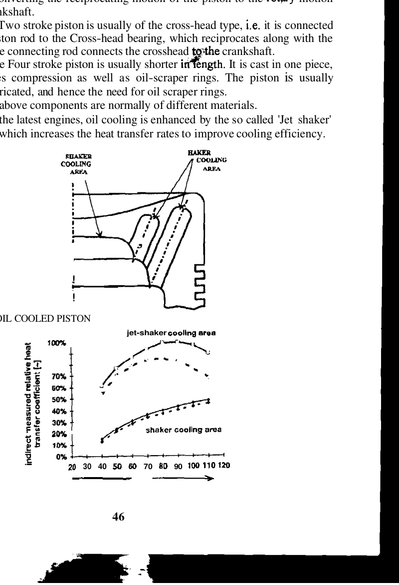
Piston cooling does not rely on static flooded channels. Instead, it utilizes the violent vertical acceleration and deceleration of the reciprocating piston to generate the "Cocktail-Shaker" (shaker effect):
- Oil Supply Path: Lubricating oil at approx. 45°C to 50°C and 4.0 bar is fed from the crosshead pin through a central central inlet pipe running up the interior bore of the hollow piston rod.
- Partial Cavity Filling: The internal cavity beneath the crown is only partially filled (approx. 40% to 50% volume). This airspace is critical; a 100% completely flooded cavity would behave as a solid hydraulic lock without dynamic movement.
- Inertial Sloshing Action: As the piston approaches Top Dead Centre (TDC) at speeds up to 10 m/s and decelerates violently, inertial forces propel the pool of cooling oil upward like a high-velocity wave, slamming it directly against the underside ceiling of the crown and forcing it into radial bore-cooling passages.
- Scrubbing the Boundary Layer: In laminar flow, a stagnant insulating film of oil forms on metal walls, severely choking heat conduction. The violent slamming impact of the cocktail shaker breaks down this boundary film, inducing intense micro-turbulence that elevates heat transfer rates by 300% to 500% compared to static pipe flow.
-
Drainage & Monitoring: As the piston approaches BDC, the oil crashes back down to the cavity floor, draining through central standpipes down the annular space between the central feed pipe and the piston rod bore. The return oil discharges through a telescopic pipe into an external sight glass equipped with a temperature sensor:
- Normal Return Temp: 55°C to 65°C (temperature rise ΔT ≈ 10°C–15°C across the piston).
- Alarm Threshold: A sudden spike above 75°C indicates piston ring blow-by, crown cracking, or reduced oil flow, requiring immediate engine load reduction.
3. Piston Skirt, Rod Fastenings & Crosshead Mechanics
Unlike four-stroke trunk piston engines—where the massive piston skirt acts as a crosshead to transmit connecting rod angular side thrust directly to the cylinder liner—large two-stroke engines transmit all side thrust to stationary crosshead guide shoes. Consequently, the two-stroke piston skirt serves a completely different, specialized purpose.
Functions of the Two-Stroke Short Skirt
- Scavenge Port Sealing: In uniflow-scavenged engines, when the piston reaches Top Dead Centre (TDC), the bottom of the piston must cover the scavenge air ports at the bottom of the liner to prevent high-pressure scavenge air from blowing uselessly into the under-piston space.
- Piston Alignment: Provides a stable guide during stroke reversal to prevent the piston crown from tilting or slapping against the liner wall.
Cast Iron Skirt & Leaded-Bronze Wear Bands
The skirt is cast from high-grade grey or nodular cast iron and bolted firmly to the underside of the forged steel crown. Cast iron is chosen because its graphite flake microstructure gives it superior sliding compatibility against the cast iron cylinder liner, preventing galling.
- Leaded-Bronze Wear Rings: Two or three circumferential grooves are machined into the outer diameter of the skirt and fitted with leaded-bronze wear bands (approx. 80% Cu, 10% Sn, 10% Pb). The bronze bands project approximately 0.20 to 0.30 mm proud of the cast iron skirt surface.
- Emergency Rubbing Surface: If the crosshead guide shoes wear or if thermal expansion tilts the piston momentarily, the soft bronze bands rub against the liner wall without scoring the iron bore, bedding down smoothly and acting as a non-scuffing sacrificial contact layer.
Piston Rod Mechanical Attachment
The piston crown and skirt assembly is secured to the upper flange of the forged steel piston rod by 4 to 8 high-tensile alloy steel studs:
- The studs are tightened using specialized hydraulic tensioning jacks to a precise elongation (typically 0.40 to 0.60 mm) to ensure uniform pre-stressing.
- Because the underside of the crown flexes slightly under cyclic gas pressure, the studs must withstand high dynamic fatigue loads. They feature reduced shank diameters (waisted studs) to distribute tensile strain over their full length, and are secured with mechanical lockplates or tab washers.
4. Piston Rings: Metallurgy, Profiles & Controlled Pressure Relief (CPR)
Piston rings are the dynamic sealing elements that convert high-pressure combustion gas energy into mechanical work. A large two-stroke piston typically carries 4 or 5 compression rings located in the upper crown lands.
Piston Ring Metallurgy & Manufacture
Piston rings are cast from specialized high-strength alloyed spheroidal graphite (SG) iron or carbidic cast iron containing chromium, molybdenum, vanadium, and copper (e.g. DAROS RS-iron). The metallurgy must satisfy three strict rules:
- The ring material must be slightly softer than the cylinder liner so that the ring acts as the primary consumable wear element.
- It must retain high elastic springiness (modulus of elasticity) at 200°C without suffering thermal relaxation.
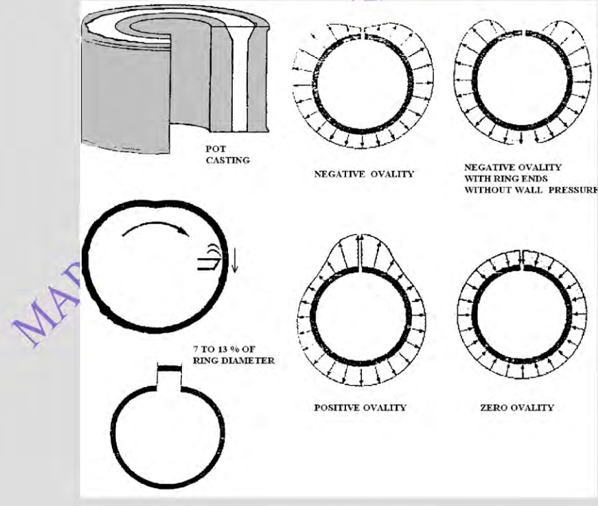
- Rings are manufactured via cam-turning of pot castings (pot-cast), machining an oval shape that produces uniform radial wall pressure when compressed into the circular cylinder bore.
Piston Ring Wear Coatings
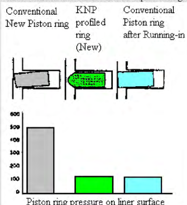
- Alucoat Running-In Layer: A soft, 0.05 mm thick coating of aluminium oxide (Al2O3) applied to the outer sliding face. During the initial 500 hours, it wears down rapidly, conforming to the microscopic wave-cut grooves of the liner without scuffing.
- Plasma-Sprayed Ceramic Coatings: Modern rings feature a 0.25 to 0.40 mm thick layer of Chromium-Ceramic (Cr-C) or diamond-like carbon applied by a high-temperature plasma arc (10,000°C). This ultra-hard layer extends piston ring service life beyond 16,000 to 24,000 running hours.
The Controlled Pressure Relief (CPR) Ring Philosophy
In older engines with plain piston rings, the No. 1 (Top) Piston Ring bore over 80% of the entire combustion pressure drop (180 bar pressure drop across a single ring!). This massive pressure forced the top ring against the cylinder liner with extreme radial force, causing severe boundary friction, scuffing, and premature ring breakage.
- The CPR Innovation: The top ring is manufactured with small, precisely calibrated radial decompression grooves (slots) milled into its upper flank.
- Pressure Distribution: The grooves allow a small, controlled amount of high-pressure combustion gas to bypass the top ring and pressurize the space above the No. 2 ring.
- Balanced Loading: Instead of the top ring bearing 180 bar, the pressure drop is split smoothly: the top ring bears approximately 100 bar, and the second ring bears 60 bar. This dramatically lowers the contact pressure of the top ring, eliminates ring collapse, and reduces liner wear by over 40%.
5. Critical Piston Ring Clearances & Failure Modes
Piston rings must be free to expand, contract, and rotate inside their grooves. During every engine overhaul, marine engineers must measure three critical ring clearances:
Clearance Checks: Maker Limits & Measurement Method
| Clearance Parameter | Acceptance value | How Measured | Consequence if Out of Specification |
|---|---|---|---|
| Vertical (Axial) Clearance | Use the engine maker's ring/groove specification; values vary with ring position and design. | Feeler gauge inserted between ring top face and groove ceiling with ring pushed fully down. | Too small: Carbon bakes and ring sticks. Too large: Gas enters underneath; ring batters and fractures groove lands. |
| Butt (End) Gap Clearance | Use the maker's specified ring gap for the ring and bore. | Place the ring square in the maker-specified bore station (often an unworn region) and measure the end gap with a feeler gauge. | Too small: Ring ends expand and butt solid, jamming tightly in bore, breaking the ring and seizing the engine! Too large: Excessive gas blow-by into scavenge space. |
| Back Clearance | Use the maker's drawing and inspection method; do not infer a universal value. | Check radial clearance behind the ring to the groove bottom using the specified inspection method. | Too small: Ring bottoms out in groove, locking ring and causing severe scuffing. |
Classic Piston Ring Failure Modes
- Ring Sticking: Caused by thermal breakdown of over-lubricated cylinder oil or incomplete combustion soot. Ash and lacquer bake into the vertical clearance space, gluing the ring firmly inside the groove. The ring can no longer follow the liner wall, triggering instantaneous gas blow-by, burning off the remaining oil film, and initiating scavenge fires.
- Ring Collapse: Occurs when high-pressure combustion gas rushes past the front sliding face of the ring faster than gas can enter the back clearance space. The external gas pressure forces the ring radially inward into the groove, breaking the seal. The ring flutters violently, shattering into pieces.
- Ring Breakage: Almost universally initiates at the ring tips adjacent to the butt gap due to fatigue bending, excessive vertical clearance causing groove hammering, or striking the wear ridge at the top of the liner stroke.
- Micro-Seizure & Scuffing: Triggered by cat fines or temporary oil starvation. Frictional heating causes micro-welding between ring and liner asperities, tearing metal and turning the ring running face into a rough, torn, dark-colored disaster zone.
Practise this in the question bank
- Crankshaft / Bearing / Cylinder — 85 questions
Found a mistake, or something unclear?
Report it in a few seconds — it goes straight to the editors.
- Two-Stroke Structure — Frame, Tie Rods, Liner, Piston & Crosshead
- Marine Crankshafts — Builds, Bedplate, Chocks & Alignment
- Engine Bearings — Renewal, Crosshead to Thrust Block
- Camshaft Chain Drive, Hydraulic Tensioners & Timing Synchronisation
- Crosshead Assembly, Guide Clearances & Piston Rod Stuffing Box
- Cylinder Liner Wear, Calibration & Cold Corrosion
- Piston Crowns, Piston Rings & Thermal Mechanics
- Exhaust Valve Actuation, Air Spring Mechanics & Spindle Metallurgy
- Engine Bedplate Foundation, Holding Down Bolts & Epoxy Chocking
- Crankshaft Alignment, Web Deflections & Bearing Clearances