

Air Compressor Construction — Pistons, Rings, Valves & Running Gear
Trunk and stepped tandem piston architecture, compression/scraper/rider rings with clearances and stagger, Hoerbiger concentric plate suction and disc
1. The compressor as two connected machines
A reciprocating compressor has two interacting sections:
- The running gear or frame end, which receives power from the driver and converts rotary motion into reciprocating motion.
- The gas end, where the piston changes the gas volume and automatic valves control suction and discharge.
A typical flow of power is:
The gas path is separate:
This separation is especially important in heavy-duty and oil-free compressors. The frame may contain lubricating oil while the cylinder is designed to prevent that oil entering the compressed gas.
Modern heavy-duty continuous-service compressors may attach one or more cylinders to a horizontal or vertical frame. The same basic principles apply from a small single-cylinder air compressor to a large multistage, multiservice process machine.
2. Frame and crankcase
The frame supports the crankshaft bearings, crosshead guides, cylinders, lubrication system, and attached piping loads. It must remain stiff enough to preserve alignment under gas forces, inertia forces, thermal distortion, and foundation movement.
2.1 Frame functions
The frame:
- carries the main bearings;
- locates the crankshaft and crank throws;
- supports the crosshead guides;
- transmits cylinder and running-gear forces to the foundation;
- encloses or supports the crankcase lubrication system;
- provides inspection access;
- supports distance pieces and packing cases where fitted; and
- provides mounting surfaces for cylinders and auxiliary equipment.
A flexible or cracked frame changes the alignment between the crankshaft, crosshead, piston rod, and cylinder. The resulting failures may include packing leakage, piston-ring wear, cylinder rubbing, bearing distress, abnormal vibration, and high power consumption.
2.2 Material and construction
Frames may be cast or fabricated from steel or cast iron according to size, pressure, speed, and manufacturer practice. The important characteristics are stiffness, dimensional stability, resistance to fatigue, and accurate bearing and guide machining.
The frame must also tolerate repeated cyclic loading. A compressor does not apply a steady force: gas pressure and inertia forces vary every revolution. Local stress concentration around bearing saddles, cylinder attachments, and crosshead guides must therefore be controlled.
2.3 Crankcase enclosure
The crankcase retains lubricating oil and prevents contamination from entering the running gear. Covers and inspection doors permit examination of:
- main bearings;
- crankpin bearings;
- connecting rods;
- oil pump and strainer;
- crosshead shoes;
- crankshaft webs; and
- counterweights.
A crankcase breather or vent prevents excessive pressure caused by oil agitation, blow-by, or temperature rise. The vent arrangement must not permit unsafe oil mist release or allow dirt to enter.
2.4 Frame inspection points
During an inspection check for:
- cracks around bearing housings;
- fretting or movement at bolted joints;
- loose foundation or frame bolts;
- oil leakage;
- abnormal oil temperature or pressure;
- loose inspection covers;
- metal particles in the oil;
- evidence of water contamination; and
- paint or grout cracks indicating movement.
A frame defect should not be dismissed as a cosmetic problem. The frame is the reference structure for the entire compressor.
3. Crankshaft
The crankshaft converts the driver’s continuous rotary motion into the reciprocating motion required by the pistons. It is usually a steel forging supported by at least two main bearings. More throws and cylinders generally require additional bearing support.
3.1 Principal features
A crankshaft includes:
- main journals;
- crankpins;
- webs;
- counterweights or balance weights;
- keyways or coupling connection;
- oil passages where pressure lubrication is used; and
- thrust-locating arrangements where required.
The crank throw determines the piston stroke:
L = 2r
where L is stroke and r is crank radius.
3.2 Crank throws and cylinder arrangement
The angular arrangement of crank throws determines piston phase, firing or compression sequence, torque uniformity, and balance. A multistage compressor must also coordinate the motion of low-pressure and high-pressure pistons so that interstage flow remains stable.
Throw arrangement affects:
- primary and secondary inertia forces;
- rocking couples;
- torque variation;
- flywheel requirement;
- vibration transmitted to the foundation; and
- the timing of suction and discharge events.
3.3 Counterweights
Counterweights offset a portion of the rotating and reciprocating mass effects. They may be integral with the shaft or separately bolted. They cannot eliminate every unbalanced force in every arrangement, but correct balancing reduces bearing load, foundation reaction, and vibration.
A missing, loose, cracked, or incorrectly installed counterweight is a serious defect. It can cause rapid bearing damage, shaft fatigue, or catastrophic failure.
3.4 Crankshaft inspection
Inspect journals and crankpins for:
- scoring;
- overheating or discolouration;
- cracks;
- taper and out-of-round;
- wiped bearing material;
- blocked oil holes; and
- fretting at fitted components.
Measure bearing clearances according to the manufacturer’s procedure. Excess clearance reduces oil-film reliability and can produce low oil pressure, knocking, and inaccurate shaft position. Insufficient clearance can cause seizure when the shaft expands or the oil viscosity rises during a cold start.
4. Main bearings
Main bearings support the crankshaft and maintain its centreline in the frame. They may be:
- anti-friction rolling bearings;
- plain sleeve bearings; or
- older adjustable babbitted two- or three-piece bearings.
The bearing type determines lubrication, inspection, clearance measurement, permissible load, and replacement procedure.
4.1 Bearing duties
A main bearing must:
- carry radial gas and inertia loads;
- maintain crankshaft alignment;
- transmit torque reactions into the frame;
- operate with an oil film or rolling contact; and
- accommodate thermal expansion and shaft movement within limits.
4.2 Bearing failure symptoms
Possible symptoms include:
- low oil pressure;
- rising bearing temperature;
- metallic particles in the sump;
- rumbling or knocking noise;
- increased vibration;
- crankshaft runout or movement; and
- oil discolouration.
Bearing symptoms must be correlated with oil condition, pressure, temperature, alignment, and load. A low oil-pressure alarm may be caused by a pump or filter problem, but it may also indicate internal bearing leakage.
5. Connecting rod
The connecting rod links the crankpin to the crosshead. It transmits both compression and tension loads as the crank rotates. The rod is subjected to alternating forces, bending effects from misalignment, and cyclic fatigue.
5.1 Construction
A connecting rod normally has:
- a crankpin end with bearing shell or bushing;
- a shank designed for stiffness and fatigue strength;
- a crosshead-end connection;
- bolts or a fitted connection; and
- provisions for oil supply where required.
The crankpin bearing must accommodate the changing load direction and maintain an oil film. Connecting-rod bolts are critical load-bearing parts; incorrect tightening or damaged threads can cause rapid failure.
5.2 Rod-load significance
Gas pressure on the piston and inertia of the reciprocating mass combine to produce rod load. Rod load is usually checked in both compression and tension because the limiting condition can differ by design.
Excessive rod load may result from:
- excessive discharge pressure;
- liquid entering the cylinder;
- overspeed;
- incorrect cylinder pressure balance;
- valve failure;
- excessive piston mass or altered components; and
- abnormal clearance or impact.
A rod-load limit is a design protection limit, not a target operating value.
6. Crosshead
A crosshead guides the piston rod and separates the rod’s reciprocating motion from the angular motion of the connecting rod. In heavy-duty compressors the crosshead is mounted in a guide and carries sliding shoes or shoes with replaceable wear surfaces.
6.1 Why a crosshead is used
Crosshead construction:
- guides the piston rod accurately;
- prevents the connecting rod from applying side thrust directly to the piston;
- allows a narrow piston and greater valve area;
- permits a longer stroke and higher capacity;
- separates crankcase oil from the cylinder gas end;
- reduces piston slap and ring wear;
- supports stronger piston designs and higher pressure; and
- permits compression at both ends of a piston in double-acting machines.
The crosshead therefore does more than merely guide motion. It is a key part of alignment, lubrication control, and cylinder cleanliness.
6.2 Crosshead shoes and guides
The shoe-to-guide clearance must allow an oil film and thermal expansion without permitting excessive movement. Excessive clearance can produce knocking and piston-rod misalignment. Insufficient clearance can cause heating and seizure.
Inspect for:
- wiped or scored shoe surfaces;
- uneven contact pattern;
- embedded dirt or metal;
- guide wear;
- loose shoe retainers;
- oil starvation; and
- evidence of frame distortion.
A crosshead problem can appear at the gas end as packing leakage or abnormal ring wear. Always investigate alignment before replacing only the visible worn part.
7. Piston rod
The piston rod transmits crosshead force to the piston. It must withstand alternating tension and compression, maintain straightness, and provide a reliable sealing surface through the packing case.
7.1 Requirements
The rod must have:
- adequate fatigue strength;
- a precise diameter and surface finish through the packing;
- corrosion and wear resistance;
- correct fit at the crosshead and piston;
- sufficient stiffness to prevent bending; and
- a secure locking arrangement.
Rod material, diameter, length, composition, and fastening arrangement are selected for compressor load and piston design.
7.2 Rod runout and alignment
Rod runout is the deviation of the rod from its intended centreline during rotation and reciprocation. Excessive runout may indicate:
- bent piston rod;
- incorrect crosshead alignment;
- frame distortion;
- cylinder misalignment;
- loose piston or crosshead connection; or
- foundation movement.
Consequences include packing leakage, rapid packing wear, piston-ring damage, cylinder scoring, and increased friction.
7.3 Tail rods and opposed plungers
Special high-pressure designs may use tail rods or opposed plungers. These arrangements balance forces or permit extreme pressure service, but they add seals, alignment requirements, and inspection points. High-pressure cylinders can use opposed single-acting ends as identical stages or as different stages with different bore sizes.
8. Piston
The piston forms the moving boundary of the compression space. Its face, rings, rider bands, rod connection, and end clearances determine sealing, capacity, friction, and mechanical reliability.
8.1 Single-acting piston arrangement
A single-acting piston compresses gas on one side only. The opposite side may be open to the crankcase or separated by a packing arrangement. The cylinder has suction and discharge events at the active end.
8.2 Double-acting piston arrangement
A double-acting piston compresses gas on both sides. Each end has suction and discharge valves, and the piston rod passes through a packing case at one end. Double acting increases capacity for a given frame size but adds valves, packing, cooling, and clearance considerations.
8.3 Piston rings and rider rings
Piston rings reduce leakage between piston and cylinder. Rider rings support the piston weight and limit metal-to-metal contact, especially in non-lubricated designs. Ring material and profile must match gas cleanliness, temperature, pressure, cylinder material, and lubrication.
Ring failure can cause:
- reduced capacity;
- increased discharge temperature;
- gas blow-by;
- crankcase contamination;
- increased power;
- cylinder scoring; and
- abnormal noise.
8.4 Piston clearances
End clearance prevents the piston from striking the head at the end of the stroke. Radial clearance allows thermal expansion and ring operation. Both must remain within the manufacturer’s limits.
Too little end clearance causes impact risk. Too much clearance reduces capacity because more gas remains trapped and re-expands during suction. Incorrect piston position can result from a wrong rod length, incorrect packing adjustment, changed gasket thickness, or a shifted crosshead.
9. Cylinder barrel and heads
A typical double-acting cylinder consists of a barrel, usually water-jacketed, with front and rear heads. The rear head may be integral with the barrel or a separate bolted component. Heads can also be water-cooled to remove compression heat.
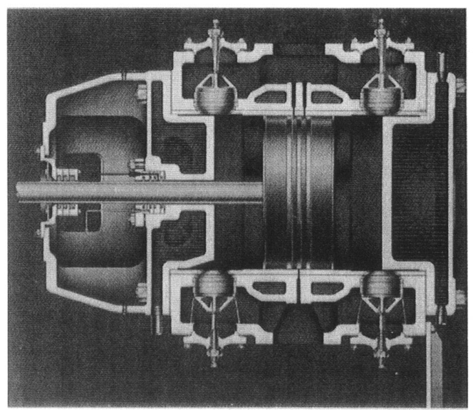
9.1 Cylinder barrel
The barrel provides the precision bore in which the piston and rings operate. It must resist:
- internal gas pressure;
- cyclic pressure loading;
- thermal gradients;
- valve impact and pulsation forces; and
- wear from rings and rider bands.
The bore finish must retain the intended surface condition without excessive roughness that damages rings or excessive smoothness that prevents suitable oil retention where lubrication is required.
9.2 Cylinder heads
Cylinder heads close the compression space and provide access to valves, clearance pockets, cooling passages, and pressure connections. They must withstand pressure and thermal cycling while maintaining gasket sealing.
Head inspection includes:
- cracks and erosion;
- gasket-face condition;
- loose or damaged valve pockets;
- blocked water passages;
- corrosion or scale;
- incorrect clearance-pocket operation; and
- evidence of piston contact.
9.3 Water jackets
Water jackets remove heat from the barrel and heads. Fouling, sludge, scale, air pockets, low flow, or excessive water temperature reduces heat transfer. The result is higher gas temperature, poorer lubrication, deposits, shorter valve life, and greater maintenance cost.
The cooling system must be drained and protected against corrosion and freezing where applicable. Chemical cleaning should follow the equipment maker’s procedure because aggressive treatment can damage materials or seals.
9.4 Valve pockets
Valve pockets locate suction and discharge valves around the cylinder barrel or in the heads. Their shape influences flow restriction, clearance volume, valve accessibility, and heat transfer.
A valve pocket that is damaged, incorrectly gasketed, or assembled with the wrong valve can create leakage, reverse flow, poor capacity, or excessive temperature.
10. Compressor valves
Automatic compressor valves open when the pressure difference across the valve overcomes spring and inertia forces, and close when the pressure difference reverses. They do not normally require a mechanical cam.
10.1 Suction valves
The suction valve admits low-pressure gas during the suction part of the cycle. It must open with low pressure loss and close securely before compression begins.
A leaking suction valve allows compressed gas to return to the suction passage. It reduces capacity, increases temperature, and may cause an abnormal indicator card.
10.2 Discharge valves
The discharge valve opens when cylinder pressure exceeds discharge pressure by enough to overcome spring and valve inertia forces. It must close without excessive impact when cylinder pressure falls.
A leaking discharge valve allows high-pressure gas to return to the cylinder during expansion or suction. The cylinder may run hot, lose capacity, and consume more power.
10.3 Valve construction
Common valve elements include:
- seat;
- plate, ring, or poppet;
- springs;
- guard or lift limiter;
- retainer; and
- gasket or sealing arrangement.
Valve materials must tolerate pressure pulsation, temperature, impact, corrosion, and any liquid or solid contamination in the gas.
10.4 Valve condition and compressor performance
Valves are often among the most maintenance-sensitive compressor components. Check for:
- broken springs;
- cracked or worn plates;
- damaged seats;
- carbon or oil deposits;
- excessive lift;
- incorrect spring arrangement;
- dirt or liquid damage; and
- incorrect installation orientation.
Valve leakage is a gas-end problem, but its effects appear throughout the machine: lower capacity, higher power, high discharge temperature, altered interstage pressure, and possible driver overload.
11. Piston-rod packing
Packing seals the moving piston rod where it passes through the cylinder head or distance piece. It prevents compressed gas escaping to the crankcase or atmosphere and prevents frame oil entering the cylinder.
11.1 Packing functions
Packing must:
- limit gas leakage;
- tolerate rod reciprocation;
- maintain sealing as pressure changes;
- control oil migration;
- dissipate heat; and
- permit inspection and adjustment.
Packing may be lubricated, minimally lubricated, or non-lubricated. Cooling may use oil, water, or a thermosiphon arrangement depending on the design.
11.2 Packing leakage
Packing leakage may be caused by:
- worn rings;
- scored or rough piston rod;
- rod runout;
- incorrect ring orientation;
- inadequate cooling;
- incorrect lubrication;
- loose or distorted packing case; or
- excessive cylinder pressure.
Do not cure packing leakage by tightening until the rings overheat. Excessive loading increases friction and can score the rod. Determine whether the root cause is alignment, cooling, lubrication, or wear.
11.3 Distance piece
A distance piece separates the cylinder from the frame. It provides space for packing, oil scrapers, vents, drains, and inspection. In oil-free or hazardous service it helps prevent frame oil from reaching the gas end and provides a controlled leakage path.
12. Oil scraper and crankcase separation
An oil scraper limits the movement of crankcase oil along the piston rod. It works with the distance piece and packing arrangement to control oil carryover.
The design objective is not merely to keep the crankcase dry. It is to maintain the required balance between:
- crankcase lubrication;
- rod-surface oil film;
- cylinder cleanliness;
- packing life; and
- allowable gas contamination.
A damaged scraper can produce oil carryover, contaminated gas, carbon deposits, valve sticking, and unsafe discharge piping. In an oil-free gas end, the frame can still be pressure-lubricated, but the separation system must be maintained.
13. Lubrication system
The running gear commonly uses a forced or splash lubrication system. Its components may include:
- oil sump;
- gear or plunger oil pump;
- suction strainer;
- pressure-regulating valve;
- oil filter;
- cooler;
- pressure gauge and switch;
- distribution passages; and
- drain and sampling points.
13.1 Lubrication objectives
Proper lubrication:
- reduces bearing and shoe wear;
- removes heat;
- flushes wear particles toward the filter;
- prevents corrosion;
- reduces friction; and
- provides an oil film between loaded surfaces.
Oil quality, cleanliness, viscosity, level, pressure, and temperature all matter. Incorrect oil can produce low pressure, foaming, deposits, seal incompatibility, or bearing damage.
13.2 Oil contamination
Inspect for:
- water or coolant in the oil;
- fuel or process gas dilution;
- metallic particles;
- carbon and sludge;
- abnormal viscosity; and
- foaming.
A clean oil sample does not prove that all bearings are healthy, but a contaminated sample is a strong reason for investigation.
14. Flow path through a two-stage compressor
A typical two-stage machine operates as follows:
Every item introduces a pressure drop or maintenance requirement. A restriction before the low-pressure cylinder reduces mass flow. A restriction between stages changes the stage pressure ratio. A restricted aftercooler or discharge line increases final discharge pressure and power.
The construction of the compressor cannot be separated from the construction of its accessories.
15. Construction comparison: trunk piston and crosshead
| Feature | Trunk piston | Crosshead compressor |
|---|---|---|
| Piston guidance | Piston skirt guides in cylinder | Crosshead and shoes guide rod |
| Frame-to-cylinder separation | Less complete | Strong separation through distance piece |
| Typical size | Small and moderate duty | Heavy-duty and high-pressure service |
| Oil control | More direct interaction with cylinder | Better separation of frame oil and gas end |
| Piston side thrust | Carried by piston skirt | Mostly carried by crosshead guide |
| Double-acting use | Limited by arrangement | Well suited to heavy-duty double acting |
| Maintenance emphasis | Skirt, rings, cylinder lubrication | Shoes, rod alignment, packing, distance piece |
Neither arrangement is universally superior. Selection depends on pressure, capacity, gas cleanliness, speed, duty cycle, cost, and maintenance capability.
16. Marine Trunk Piston Architecture
In marine reciprocating air compressors (such as Hamworthy, Sperre, Hatlapa, Yanmar, and Tanabe), the machine is built strictly on Trunk Piston Construction. Unlike 2-stroke slow-speed main propulsion engines—which require massive crossheads, guide shoes, and piston rods to isolate cylinder combustion from the crankcase—marine auxiliary air compressors eliminate the crosshead entirely to achieve extreme compactness and high rotational speed.
A. How the Marine Trunk Piston Operates
In a trunk piston compressor, the piston connects directly to the top end of the connecting rod via an internal, oscillating gudgeon pin (wrist pin) fitted inside the piston pin bosses:
- Direct Side-Thrust Transmission: As the crankshaft rotates, the connecting rod swings through an angular arc, imposing an alternating lateral side-thrust. In a trunk compressor, this side-thrust is absorbed directly by the cylindrical piston skirt bearing against the cylinder liner wall.
- Compact Vertical Architecture: Because there is no crosshead, no piston rod, and no stuffing box, the machine is compact, has low overall height, and fits easily on engine room auxiliary machinery flats.
- High Operating Speed: Without the massive reciprocating weight of crosshead shoes and guide assemblies, reciprocating inertia is minimal. This allows marine compressors to run at 750 to 1800 RPM, directly coupled to standard 4-pole or 2-pole AC induction motors.
- Lubrication: Cylinder liners are lubricated either by oil mist splashed violently from the crankcase by rotating crank webs or through pressurized rifle drillings in the connecting rod feeding the gudgeon pin and skirt.
17. The Stepped Tandem (Differential) Piston Working Principle
In commercial marine merchant vessels, starting air must be compressed from atmospheric pressure (1 bar) to 30 bar gauge (31 bar absolute). As proven in thermodynamics, doing this in a single stage produces destructive discharge temperatures exceeding 400°C and destroys volumetric efficiency.
To achieve two-stage compression with intercooling while keeping the compressor as small, light, and reliable as possible, marine manufacturers (such as Hamworthy, Sperre, Hatlapa, and Tanabe) developed the legendary Stepped Tandem Piston (frequently referred to as a Differential Piston).
A. Mechanical Geometry: Two Pistons in One Casting
A stepped tandem piston is a single, precision-machined aluminum alloy or cast iron piston casting that has two distinct outer diameters:
- The Upper Crown (Large Diameter - DLP): Forms the ceiling of the piston. The volume enclosed between this upper crown and the cylinder head forms the Low-Pressure (LP) Stage Chamber.
- The Lower Trunk (Small Diameter - DHP): Extends downward into the lower cylinder bore, containing the gudgeon pin and skirt.
- The Annular Step / Shoulder (Differential Area): The transition between the large upper diameter and the smaller lower diameter forms a horizontal annular shoulder. The enclosed space between this downward-facing shoulder and the cylinder block's stepped landing forms the High-Pressure (HP) Stage Chamber!
Effective Piston Areas
The effective compression surface areas for the two stages are:
LP Stage Compression Area: ALP = π4 × DLP2
HP Stage Annular Compression Area: AHP = π4 × (DLP2 − DHP2)
The HP stage uses the differential annular step area—requiring ZERO additional connecting rods or crankpins!
B. The 360-Degree Compression Cycle
To understand why this design is so brilliantly efficient, trace what occurs during one complete crankshaft revolution (two strokes):
-
The Downward Stroke: LP Inhalation + HP Compression & Delivery
As the crank pulls the stepped piston downward from TDC toward BDC:
- LP Stage: The volume above the upper crown expands. Pressure inside the LP cylinder drops below atmospheric, causing the LP Suction Valve to pop open. Fresh atmospheric air is drawn into the LP cylinder throughout the entire downward stroke.
- HP Annular Stage: Simultaneously, the downward-moving annular shoulder travels closer to the cylinder block's fixed stepped landing! The volume of the annular HP space contracts. Air previously trapped in the annular space is compressed from interstage pressure (5.5 bar) up to full discharge pressure (30 bar gauge). When pressure exceeds line resistance, the HP Delivery Valve lifts, discharging hot, high-pressure air through the aftercooler into the ship's 30-bar starting air reservoirs!
-
The Upward Stroke: LP Compression & Intercooling + HP Inhalation
As the crank pushes the stepped piston upward from BDC toward TDC:
- LP Stage: The volume above the upper crown contracts. The fresh air charge is compressed from atmospheric pressure up to intermediate pressure (~5.5 bar). At ~5.5 bar, the LP Delivery Valve opens, forcing the air out through the water-cooled intercooler tubes, where heat is rejected and air volume shrinks.
- HP Annular Stage: Simultaneously, the annular shoulder moves upward away from the fixed block step, causing the annular volume to expand. The pressure in the annular space drops below interstage pressure, causing the HP Suction Valve to open. Cold, dense air from the intercooler is inhaled directly into the annular HP space, completely filling it in preparation for the next downward stroke!
The Thermodynamic & Mechanical Masterstroke
Notice that in a stepped tandem compressor, compression work is performed on BOTH the upstroke (LP stage) and the downstroke (HP stage)!
In a conventional single-acting compressor, all work is crammed into the upward stroke, requiring a massive flywheel to store kinetic energy and violently jerking the motor. In a stepped machine, work is distributed across all 360 degrees of rotation. This results in smooth, balanced motor driving torque, minimal cyclic speed variation, and exceptional mechanical balance.
18. Piston Rings, Sealing & Oil Scraper Rings in Trunk Compressors
Because the trunk piston has no external crosshead or separation diaphragm, the piston rings must perform two critical, opposite sealing functions under extreme thermal and pressure differentials:
A. Compression Rings (Gas Sealing)
Compression rings prevent high-pressure air from leaking backward past the piston into the crankcase (blow-by):
- LP Compression Rings (Top Crown): 2 to 3 cast-iron or nodular iron rings fitted on the large diameter crown. They seal intermediate pressure (up to 5.5 bar) at temperatures around 130°C to 150°C. Standard butt-end or angle-cut gaps (0.3 to 0.5 mm) are used.
- HP Compression Rings (Stepped Trunk): 3 to 4 heavy-duty rings fitted on the smaller stepped diameter. These rings must withstand severe pressures up to 30 to 35 bar. In modern marine compressors, these are spheroidal graphite iron or bronze-filled PTFE with stepped lap joints to eliminate straight gas blow-by paths under high differential pressure.
B. Oil Control Scraper (Wiper) Rings (Crankcase Protection)
In trunk compressors, the crankpin bearings and cylinder walls are lubricated by pressurized oil delivered through the crankshaft rifle drillings and violently splashed by the rotating crank webs. If this oil reaches the high-temperature air chambers, disaster follows.
At the bottom of the piston skirt, one or two specialized oil scraper rings are fitted:
- Dual Knife-Edge Profile: The upper face is chamfered to hydrodynamically glide over the oil film during the piston's upward stroke. On the downward stroke, the sharp lower scraping edges shear excess oil cleanly from the cylinder liner wall.
- Radial Skirt Drainage Ports: Directly behind the scraper ring groove, multiple radial holes (∅ 3 to 4 mm) are drilled through the piston skirt wall. Oil scraped into the ring groove escapes through these drillings and drains directly into the hollow piston interior and back into the crankcase sump.
Danger: Consequences of Scraper Ring Failure: The Starting Air Explosion Hazard
If scraper rings become worn, loose in their grooves, or have their drainage holes choked with carbonized sludge, oil control collapses. Splash oil is pumped upward into the LP and HP stages.
Under 30 bar pressure and discharge temperatures reaching 140°C to 160°C, this lubricating oil vaporizes, cracks into volatile hydrocarbon fractions, and forms glowing carbon embers on discharge valves. When an ember ignites oil mist inside the discharge pipe or starting air line, a devastating starting air explosion occurs, capable of rupturing air pipes and killing engine room personnel.
19. The 4 Compressor Ring Profiles & Anatomical Functions
In a marine auxiliary reciprocating compressor, the piston assembly operates under cyclic gas pressures up to 35 bar, discharge temperatures exceeding 150°C, and violent connecting rod angular acceleration. To handle these demands, four specialized ring profiles are employed across different stages and compressor types.
Core Operating Distinctions:
- Piston Sealing Rings (1 & 2): Function solely to seal high-pressure gas. They possess inherent radial spring tension and self-energize outward against the cylinder bore.
- Oil Scraper Rings (3): Fitted on the lower trunk skirt to wipe splash oil downward into radial skirt drainage ports.
- Rider Guide Rings (4): Do NOT seal gas. They act as sacrificial radial bearings supporting piston mass and connecting rod side-thrust in oil-free control air compressors or composite aluminum pistons.
20. Dynamic Gas-Energized Sealing Physics
A piston ring does not seal purely by its own spring tension. In fact, inherent mechanical tension provides only 10% to 15% of the total radial sealing force. The remaining 85% to 90% is generated dynamically by gas pressure self-energization.
21. Oil Scraper Rings & Skirt Drainage Ports
In all trunk-piston compressors, crankcase oil is thrown violently against the bottom cylinder walls. If oil migrates past the piston into the high-temperature compression chambers, it bakes onto delivery valves and causes **Starting Air Line Explosions**.
Danger: The Chain Reaction: Scraper Failure → Starting Air Line Explosion
- Choked Skirt Drain Holes: Carbon sludge clogs the radial drainage holes behind the scraper ring.
- Upward Oil Pumping: Without a drain escape path, the scraper ring hydraulically locks and vigorously pumps crankcase oil upward past the compression rings.
- Carbonization on 30-Bar Delivery Valves: Under 30 bar pressure and 150°C discharge heat, oil vaporizes and cracks, depositing thick, sticky carbon onto the HP delivery valve plates and springs.
- Valve Leakage & Thermal Runaway: Leaking discharge valves allow superheated 30-bar compressed air to re-enter the cylinder, driving localized temperatures past 400°C. Glowing carbon embers auto-ignite the oil mist in the discharge line, creating a high-velocity shockwave explosion that can shatter the ship's starting air manifold!
22. Ring Joint Geometry: Butt, Scarf & Step-Cut Profiles
23. Working Principle of Automatic Pressure-Operated Valves
Unlike internal combustion engine valves that are mechanically opened and closed by rotating camshafts, rocker arms, and pushrods, marine reciprocating air compressor valves are 100% automatic and differential-pressure operated.
They open and close solely in response to the pressure differential (ΔP) acting across the valve plate against the resisting force of calibrated helical closing springs:
- Opening Event: When cylinder gas pressure drops below manifold pressure (suction) or exceeds manifold pressure (discharge) by enough margin to overcome spring preload and plate inertia, the valve plate lifts off its seat.
- Closing Event: As the piston approaches dead center and gas flow decelerates, differential pressure collapses. The calibrated springs snap the plate back onto its seat before stroke reversal occurs, preventing reverse gas flow (slip).
Warning: The Severe Cyclic Impact Reality
Consider a standard 2-stage marine air compressor running at 1,800 RPM: each valve plate opens, travels to maximum lift, arrests against the guard, and slams shut onto its seat 30 times every single second (108,000 times per hour)!
Any uneven seating, excessive lift, lack of dampening, or hydraulic liquid slugging will cause high-cycle fatigue cracking and explosive fracture of the valve plate within days.
24. Exploded Architecture of Hoerbiger Concentric Plate Valves
The Hoerbiger Concentric Multi-Ring Plate Valve is the undisputed standard in marine starting air compressors (Hamworthy, Sperre, Hatlapa, Tanabe). It provides maximum flow area for a given pocket diameter while maintaining low moving mass and superior structural integrity.
25. Suction vs Discharge Valves: Differences & Anti-Inversion Safeguards
A classic blunder made by inexperienced marine engineers during cylinder head overhaul is installing a valve upside down or interchanging suction and discharge valves. The mechanical consequences are catastrophic.
Mechanical Anti-Inversion Safeguards
To prevent human error during overhaul, quality marine compressor manufacturers incorporate physical safeguards:
- Asymmetric Locating Dowel Pins: The cylinder head pocket and valve body have offset locating pins that prevent the valve assembly from entering the pocket if turned upside down.
- Different Pocket Diameters: In many modern compressors (e.g. Sperre Classic and Tanabe models), the suction valve pocket diameter is deliberately machined slightly larger than the discharge valve pocket, making it physically impossible to drop a discharge valve into a suction pocket.
- Visual Laser Marking & Directional Arrows: Valve guards and seats are laser-engraved with flow arrows (→) and stamped "CYLINDER SIDE" or "DISCHARGE".
26. Concentric Valve Component Anatomy: Dampening Plates & Lift Geometry
Why Dampening & Cushion Plates Are Vital
When high-pressure gas accelerates the valve plate off its seat, the plate reaches speeds of 5 to 10 m/s in less than two milliseconds. If this high-speed plate strikes the rigid steel guard plate directly, metal-to-metal shock causes rapid embrittlement, edge chipping, and destructive ring bouncing (flutter).
To eliminate this, a dampening or cushion plate is interposed between the valve plate and the springs:
- Pneumatic Air Pocket: As the valve plate nears the cushion plate, the thin film of trapped gas between them is squeezed, creating progressive pneumatic resistance that smoothly decelerates the plate.
- Friction Damping: The micro-sliding contact between the valve plate and dampening plate absorbs kinetic resonance, killing valve flutter and preventing the valve from reopening erratically during the stroke.
27. Mechanical motion through the compressor
A reciprocating compressor receives rotary motion from an electric motor, engine, turbine, or other driver. The crankshaft carries eccentric crank throws. A connecting rod links each crankpin to a crosshead. The crosshead moves along a straight guide and drives the piston rod and piston.
One crank revolution produces one piston cycle. With a simple crank-slider mechanism, the piston position is not a perfect sine wave because the connecting rod has finite length. The angularity of the connecting rod produces a secondary component of piston acceleration.
The running gear must transmit gas pressure forces in both compression and tension, accelerate and decelerate the moving masses, maintain alignment, and survive millions of load cycles. Correct operation therefore depends on the entire mechanical chain rather than on the piston alone.
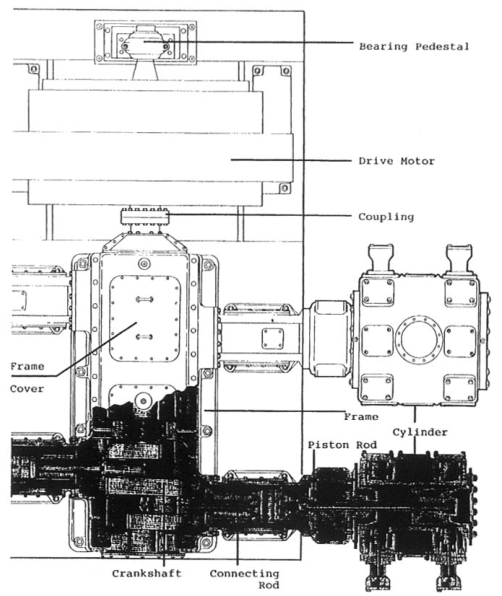
28. Crankshaft geometry
2.1 Crank radius and stroke
The crank radius r is the distance from the crankshaft centreline to the crankpin centreline. The piston stroke is approximately:
L = 2r
A longer stroke can increase displacement for a given bore, but it also increases piston speed, rod motion, inertia loading, and package size. Speed, bore, stroke, and cylinder arrangement must be selected together.
2.2 Crankshaft parts
A compressor crankshaft contains:
- main journals supported by main bearings;
- crankpins supporting connecting rods;
- webs connecting journals and crankpins;
- counterweights;
- coupling or flywheel attachment;
- oil passages where pressure lubrication is used; and
- locating or thrust features.
The shaft must resist alternating bending, torsion, bearing reactions, and local stress concentrations. Fillets at journals and crankpins are carefully designed because sharp changes in section raise fatigue stress.
2.3 Crank throws and phasing
The angular position of each throw determines the phase of each cylinder. Phasing is selected to balance forces, distribute torque, maintain acceptable interstage timing, and control discharge pulsation.
A multistage compressor may use separate cylinders with different bore sizes. The low-pressure cylinder handles the larger inlet volume; the high-pressure cylinder handles a smaller volume at greater pressure. The crank arrangement must accommodate their different gas and inertia loads.
2.4 Counterweights
Counterweights are placed to oppose centrifugal forces from rotating masses and to reduce selected components of reciprocating inertia. A rotating mass can be balanced completely with an appropriate counterweight. A reciprocating mass cannot generally be completely balanced by a single rotating mass because its motion is linear and periodic.
Counterweight changes are not an operating adjustment. Removing, replacing, or relocating a counterweight changes shaft balance and can create dangerous vibration and bearing load.
29. Crosshead and guide
The crosshead changes the angular movement of the connecting rod into straight-line movement of the piston rod. It runs in a guide fixed to the frame and carries replaceable shoes or machined bearing surfaces.
4.1 Crosshead components
A crosshead assembly may include:
- crosshead body;
- crosshead pin;
- connecting-rod bushing;
- upper and lower shoes;
- shoe retainers;
- guide surfaces;
- piston-rod threaded connection;
- lock nut and locking device; and
- oil passages.
The crosshead pin may be fixed or allowed to float laterally or rotate according to design. Retaining rings, caps, or other features control lateral movement.
4.2 Crosshead guidance
The guide must maintain piston-rod alignment while supporting side thrust generated by connecting-rod angularity. Excessive guide clearance allows the crosshead to move, causing:
- piston-rod runout;
- packing leakage;
- piston-ring and rider-ring wear;
- cylinder scoring;
- crosshead knocking; and
- uneven shoe loading.
Insufficient clearance prevents the oil film from forming and may cause overheating or seizure. Clearances must be measured against the manufacturer’s limits; generic values are unsafe.
4.3 Crosshead lubrication
In a pressure-lubricated frame, oil may travel through the crankshaft and connecting rod to the crosshead pin bushing and shoes. Oil quality and flow must be sufficient at cold start as well as normal operating temperature.
Check:
- oil passages;
- crosshead supply holes;
- shoe contact pattern;
- guide scoring;
- shoe thickness;
- pin and bushing clearance; and
- evidence of oil starvation.
4.4 Piston-rod connection
The piston rod may be screwed into the crosshead and locked with a nut, or joined using a floating or pre-stressed coupling. Locking devices can include castellated nuts, dowels, set screws, multi-bolt locks, or hydraulic pre-stressing arrangements.
The connection must remain tight under alternating tension and compression. Incorrect locking or torque can allow the rod to turn, change piston end clearance, loosen the piston, or damage the crosshead.
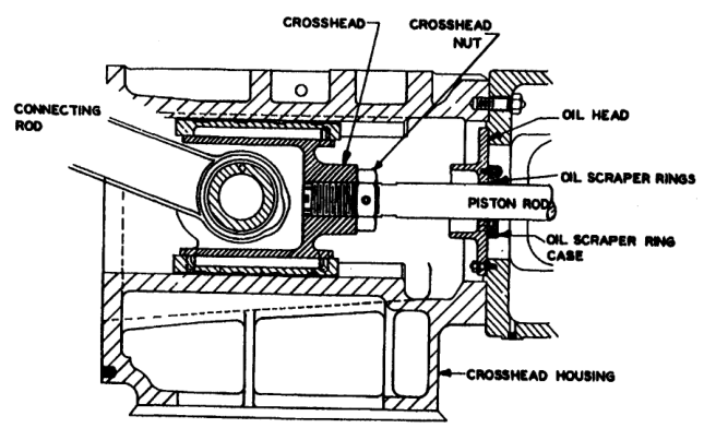
30. Piston rod and rod column loading
The piston rod carries the force from the crosshead into the piston. In a horizontal or vertical cylinder it may be loaded in tension, compression, or both during a revolution.
5.1 Compression and tension
When gas pressure and inertia act so that the piston pushes against the rod, the rod is in compression. A long slender rod can deflect or buckle under compression. When the force reverses, the rod is in tension and stretches elastically.
The rod must be designed for the combined effects of:
- gas pressure difference;
- inertia force;
- rod length and diameter;
- piston mass;
- temperature;
- crosshead alignment; and
- cylinder pressure pulsation.
5.2 Frame or rod load
Frame load is the load that the compressor frame and running gear can safely carry in tension and compression. It includes the connecting rod, bolts, crosshead pin, piston rod, bearings, crankshaft, and related structure.
A useful preliminary pressure-force relationship is:
F = P × A
For an approximate differential cylinder load:
F ≈ (pd-ps)Anet
where Anet accounts for piston-rod area where applicable. Exact compression and tension calculations must include the pressure acting on each piston face and the instantaneous inertia force.
The weakest loaded component may govern the allowable frame or rod load. A rod can appear strong while the crosshead pin bushing, connecting-rod bearing, bolts, or frame is overloaded.
5.3 Conditions that increase rod load
Rod or frame load can increase because of:
- discharge pressure above design;
- suction pressure below design;
- excessive pressure ratio;
- liquid in the cylinder;
- overspeed;
- altered gas composition or density;
- incorrect relief-valve setting;
- blocked discharge piping;
- wrong cylinder clearance; and
- abnormal valve operation.
Operating outside the specified pressure envelope can damage parts even when the motor current appears normal.
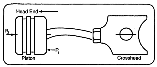
31. Gas forces and inertia forces
The running gear is acted on by two broad categories of force:
- Gas forces, caused by pressure acting on piston areas.
- Inertia forces, caused by accelerating and decelerating piston, piston-rod, crosshead, and connecting-rod masses.
Friction and bearing reactions add further loads. The resultant changes continuously with crank angle.
6.1 Gas force
For a piston face:
Fg = pA
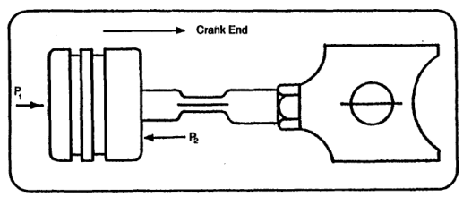
For a double-acting piston, the net force depends on the pressure on the head end, crank end, and piston-rod area. Suction and discharge pressure vary during valve opening, closing, compression, and expansion; therefore the instantaneous force is not simply the difference between receiver and atmospheric pressure.
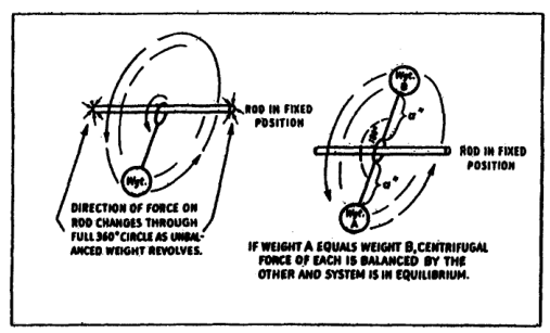
6.2 Rotating-mass inertia
Rotating masses create centrifugal force. In simplified form:
Fc = mrω²
where m is rotating mass, r is radius, and ω is angular velocity.
The force increases with the square of speed. A small speed increase can therefore produce a substantial increase in bearing and foundation loading.
6.3 Reciprocating-mass inertia
The piston, piston rod, crosshead, and the reciprocating portion of the connecting rod accelerate and decelerate. Their inertia force has primary and secondary components.
A simplified acceleration expression is commonly represented as:
a ≈ rω²(cosθ + r/lcos2θ)
where:
- r is crank radius;
- l is connecting-rod length; and
- θ is crank angle.
The first term varies once per revolution. The second varies twice per revolution.
6.4 Primary force
Primary force occurs at shaft speed. It contains contributions from rotating and reciprocating masses. Counterweights and suitable crank arrangements can reduce it significantly.
6.5 Secondary force
Secondary force occurs at twice shaft speed and results from connecting-rod angularity and reciprocating mass. It cannot generally be eliminated by ordinary counterweights. Cylinder arrangement and foundation design are therefore important.
The two significant vibration periods are:
- primary: one cycle per shaft revolution;
- secondary: two cycles per shaft revolution.
Vibration frequency can help distinguish a rotating imbalance from a reciprocating or twice-speed problem, but diagnosis should include phase, amplitude, load, and operating condition.
32. Forces and couples
A force acts through a line. A couple is produced when equal or related forces act in different planes or have an offset moment arm. A compressor may have acceptable net force but still transmit a significant couple to its foundation.
7.1 Primary and secondary couples
In a multicylinder machine, inertia forces from individual cranks may not act in the same plane. Their offset creates a moment attempting to rotate the machine about the shaft axis. This produces primary and secondary couples.
Couples depend on:
- crank spacing;
- cylinder arrangement;
- crank phase angle;
- piston mass;
- connecting-rod length;
- cylinder centre distance; and
- counterweight placement.
7.2 Balanced-opposed arrangement
In a balanced-opposed compressor, cylinders are arranged on opposite sides of the frame. With correct phasing, piston forces can cancel substantially. Closely spaced cranks reduce the moment arm and therefore reduce primary and secondary couples.
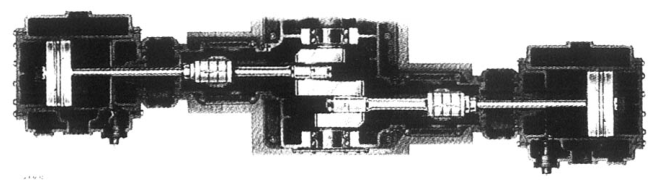
The arrangement may still transmit residual forces and pulsation. “Balanced” does not mean vibration-free; it means that selected forces and couples are reduced by geometry and phasing.
7.3 V and Y arrangements
A V or Y compressor changes the direction of forces through the cylinder angle. Some force components can be transferred or combined in a way that reduces foundation loading, but secondary forces may remain. A single-cylinder or Y-type machine can require foundation design to absorb unbalanced components that cannot be cancelled by the crank arrangement.
7.4 Force-balance table
The source gives relative force and couple values for several arrangements. The exact values depend on the machine, but the design lesson is general:
- counterweights can eliminate or reduce selected primary components;
- secondary force is more difficult to balance;
- opposed cylinders can cancel force through equal and opposite motion;
- close crank spacing reduces couple moment; and
- foundation design remains necessary even on a balanced machine.
33. Foundation and alignment connection
The foundation receives the remaining static, gas, inertia, and couple loads. It must be sufficiently massive and stiff to prevent sliding, rocking, tilting, or loss of alignment.
Poor foundation conditions can cause:
- frame distortion;
- crankshaft misalignment;
- bearing edge loading;
- crosshead shoe wear;
- piston-rod runout;
- packing failure;
- piston and cylinder scoring; and
- pipe stress.
The foundation and compressor must be treated as a dynamic system. A strong compressor on a weak or uneven foundation is not a reliable installation.
8.1 Alignment path
The alignment path is:
A defect anywhere in this chain can appear at another location. For example, a foundation shift can present as a packing leak; a bent piston rod can present as rider-ring wear; a worn crosshead shoe can present as cylinder scoring.
8.2 Piping forces
Suction, discharge, and interstage piping must not impose excessive external forces or moments on the cylinder. Thermal expansion, unsupported coolers, rigid connections, and pulsation bottles can distort the machine.
Piping support must be checked during installation and after maintenance because a moved support or altered gasket stack can change alignment.
34. Mechanical balance and operating speed
Speed influences nearly every mechanical load:
- piston speed increases approximately with speed;
- inertia force increases approximately with speed squared;
- valve impact frequency increases with speed;
- bearing heat generation increases with speed and load; and
- vibration may approach a structural or foundation natural frequency.
A compressor must not be oversped to obtain extra capacity without confirming rod load, valve dynamics, lubrication, cooling, and vibration limits. Capacity improvement through speed may be much more expensive mechanically than the apparent increase in flow suggests.
9.1 Resonance risk
If an excitation frequency approaches a natural frequency of the frame, foundation, piping, or connected structure, vibration amplitude may rise sharply. Excitation sources include:
- one-times shaft speed;
- twice shaft speed;
- cylinder firing or compression frequency;
- valve-impact frequency; and
- pressure pulsation frequency.
Avoiding resonance requires design analysis, measurement, and controlled operating speed. A vibration alarm should not be defeated simply because the compressor continues to deliver air.
35. Worked reasoning example
Problem
A two-stage compressor develops a new frame knock after a maintenance overhaul. Oil pressure is slightly lower than normal, vibration is highest near the crankcase, and the knock increases with speed.
Reasoning
- A speed-related knock suggests a running-gear or rotating component rather than a purely gas-end valve fault.
- Slightly low oil pressure raises suspicion of internal leakage, a dirty strainer, or bearing clearance.
- The maintenance history makes incorrect bearing assembly, loose connecting-rod bolts, incorrect crosshead clearance, or a loose counterweight possible.
- Stop the compressor and inspect oil for metal.
- Verify pump operation, filter condition, and relief-valve setting.
- Measure main-bearing, crankpin, and crosshead clearances.
- Check counterweight fasteners and crankshaft runout.
- Check foundation and coupling fasteners.
- Do not continue operating solely because pressure and capacity remain normal.
The machine may continue to deliver air while a bearing or fastener progresses toward catastrophic failure.
36. Cooler Construction: Finned Tubes & Water-in-Tube Flow
Marine compressor intercoolers and aftercoolers are shell-and-tube or matrix-type heat exchangers constructed to withstand continuous marine vibration, aggressive cooling seawater, and high pulsating air pressures.
Key Constructional Features
- Water-in-Tube Flow: Cooling water flows through the inside of the tubes, while compressed air flows across the exterior. This makes mechanical cleaning of marine silt and marine growth straightforward by removing the end covers and brushing the tube bores.
- External Finned Tubes: Because the heat transfer coefficient of stagnant air is only 20–50 W/m²K compared to water's 2,000–4,000 W/m²K, the exterior surface area of the tubes is multiplied 4- to 8-fold using spirally wound copper wire or stamped aluminum-brass fins.
- Thermal Expansion Compensation: Marine coolers use a floating tube plate design or U-tube bundle to allow free axial expansion without shearing the tube-to-tubesheet rolled joints.
- Galvanic Corrosion Protection: High-purity zinc sacrificial anodes (pencils) are screwed into the cast iron or bronze water end-covers. These must be inspected every 500 running hours and replaced when 50% consumed.
Practise this in the question bank
- Air Compressor (motor) — 6 questions
Found a mistake, or something unclear?
Report it in a few seconds — it goes straight to the editors.
- Air Compressor Principle, Thermodynamics & Multistage Advantages
- Air Compressor Types & Classification
- Air Compressor Construction — Pistons, Rings, Valves & Running Gear
- Air Compressor Working — Cycle, Volumetric Efficiency, Coolers & Capacity
- Air Compressor Operations — Lubrication, Drains & Running
- Air Compressor Maintenance — Lapping, Clearances & Overhaul
- Air Compressor Safety — Relief Devices, Receivers & SOLAS
- Air Compressor Troubleshooting — Interstage Pressure & Fault Finding