

Cylinder Liner Wear, Calibration & Cold Corrosion
Master marine cylinder liners: bore cooling, cold corrosion acid chemistry, cloverleaf wear, micrometer calibration, wear limits, and wave-cut refurbishment.
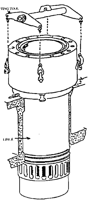
1. Cylinder Liner Construction, Metallurgy & Tangential Bore Cooling
The cylinder liner provides the cylindrical combustion chamber within which the piston reciprocates, containing combustion pressures exceeding 180 to 220 bar and peak gas temperatures reaching 1800°C to 2000°C. In large two-stroke crosshead marine engines, cylinder liners are cast separately from the engine cylinder block (jacket/entablature) for five fundamental engineering reasons:
- Metallurgical Optimization: The stationary entablature requires rigidity and is cast from standard grey iron or fabricated from mild steel. In contrast, the liner demands a specialized, highly alloyed pearlitic cast iron containing chromium, molybdenum, vanadium, copper, and controlled phosphorus (to precipitate a hard wear-resistant steadite network and self-lubricating flake graphite pockets).
- Unrestricted Thermal Expansion: During full-load operation, the liner inner surface operates at 200°C–280°C while the surrounding cylinder block remains at 70°C–80°C. The liner is clamped firmly at its upper flange by the cylinder head but is completely free to expand axially downwards through bottom sealing rings. If cast integrally with the block, massive thermal stresses would crack the structure.
- Replacement Economy: The cylinder block is designed for the 30-year lifetime of the vessel, whereas the liner is a consumable wearing component designed for a service life of approximately 60,000 to 80,000 running hours (about 8 to 12 years).
- Casting Quality & Integrity: Separating the thin-walled, geometrically complex liner from the massive engine block eliminates severe cooling shrinkage defects and residual casting stresses.
- Scavenge Port Architecture: In uniflow-scavenged two-stroke engines, scavenge ports must be cast into the lower trunk at a precise swirl angle (typically 15° to 20° to the radial axis) to generate optimal upward helical air swirl.
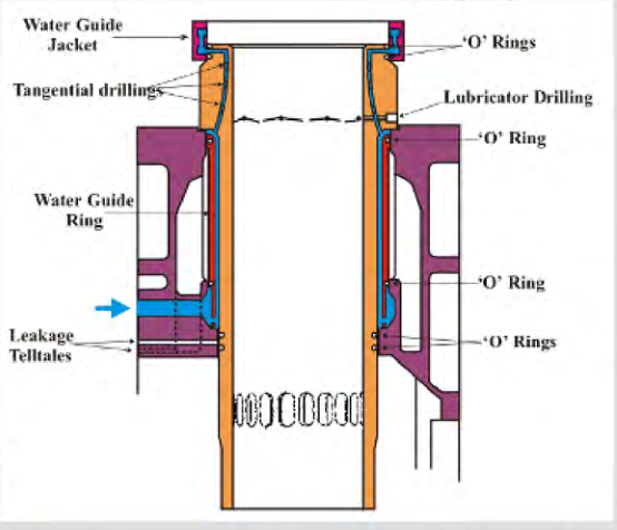
The upper flange uses tangential bore cooling, while the lower body remains free to expand downwards through the O-ring tell-tale seals.
The Thermal-Mechanical Paradox & Tangential Bore Cooling
To withstand peak combustion pressures of 200 bar, the upper section of the cylinder liner must be constructed with massive wall thickness (often 80 to 120 mm thick) to restrict mechanical hoop stress (σhoop = P·d / 2t) below the material fatigue limit.
However, increasing wall thickness creates an acute thermal barrier:
- Thermal conductivity through thick cast iron is low. Heat from combustion gas cannot escape quickly to outer cooling water jackets.
- If cooled purely on the outer circumference, the working surface temperature would surge past 350°C. At this extreme temperature, lubricant oil films burn off, cast iron loses tensile strength, and rapid micro-seizure ensues.
- Conversely, excessive cooling drops wall temperatures below 140°C, precipitating corrosive sulfuric acid.
The Tangential Bore Cooling Solution
To solve this paradox, engine designers employ tangential bore cooling. A series of angled drillings (typically 15 to 25 mm diameter) are bored upward from the lower shoulder of the upper flange at an angle of 15° to 20° to the vertical axis:
- The cooling drillings bring cooling water within 20 to 25 mm of the hot combustion running surface.
- The massive solid outer collar remains intact and cool, providing the structural hoop strength required to contain peak firing pressures.
- The bore angles are arranged tangentially so that cooling water swirls continuously, ensuring uniform peripheral temperature distribution and eliminating hot spots behind exhaust valves.
2. The Four Classical Wear Regimes & Cloverleaf Wear
Cylinder liner wear is the progressive loss or deformation of the bore surface over operating time. Wear rate, allowable ovality and condemnation criteria depend on the liner design, operating history and engine maker's manual; no single rate is a safe universal limit. Liner degradation occurs through several interacting wear regimes:
1. Abrasive Wear
Caused by hard foreign particulate matter trapped between reciprocating piston rings and the liner wall:
- Sources: Refinery catalytic fines (Al2O3 and SiO2 with Mohs hardness 8.0–8.5) introduced via poorly centrifuged heavy fuel oil; airborne silica sand drawn through intake turbocharger filters; hard carbon ash crusts flaking off over-lubricated piston crowns.
- Appearance: Severe vertical abrasive scoring tracks, micro-grooving, and loss of hydrodynamic plateau honing finish.
2. Adhesive Wear (Scuffing / Micro-Seizure)
Occurs under boundary lubrication conditions when the hydrodynamic oil film ruptures completely:
- Microscopic metal asperities on the piston ring and liner make direct dry contact under high temperature and pressure, generating instantaneous localized friction flash temperatures (> 1000°C) that cause micro-welding.
- As the piston continues its stroke, the micro-welds tear apart violently, plucking chunks of metal from the surface. In severe cases, scuffing escalates into total piston seizure and scavenge fires.
3. Corrosive Wear
The electrochemical dissolution of cast iron caused by acids formed during combustion:
- Heavy fuel oils contain up to 3.5% sulfur (and VLSFO contains up to 0.50% sulfur). Sulfur oxidizes into SO2 and SO3, combining with combustion moisture to form gaseous sulfuric acid (H2SO4).
- If the liner wall temperature drops below the Acid Dew Point (130°C to 160°C), sulfuric acid condenses as a liquid film, attacking the pearlite matrix and dissolving iron into iron sulfate.
4. Cloverleaf Wear
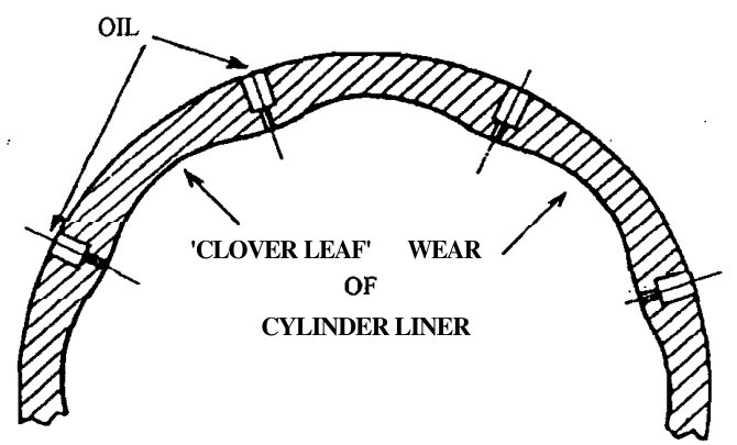
Cloverleaf wear (or cloverleafing) is localized corrosive wear between cylinder-oil injection points on designs that use discrete quills around the liner. Alkaline oil neutralizes acid more effectively near each feed point; the less-protected regions between them can wear faster, producing a lobed bore. The pattern depends on the liner, oil distribution, fuel, temperature and operation, so confirm it by circumferential measurements rather than appearance alone.
Cloverleafing Physics & Prevention
Cylinder oil containing alkaline additives (e.g. BN 40 to 100) is injected through 6 to 8 quills spaced around the liner circumference. In the immediate vicinity of each quill, the concentration of alkaline additive is high, effectively neutralizing condensing sulfuric acid.
However, midway between two adjacent quills, the oil film thins and the alkaline reserve is completely exhausted before reaching the next quill. Un-neutralized sulfuric acid attacks the cast iron vigorously, gouging out scalloped wear troughs. Over time, the internal circumference resembles a multi-lobed cloverleaf.
- Remedy 1: Re-cut oil distribution grooves with upward angling to ensure piston ring edges drag oil circumferentially.
- Remedy 2: Modern engines adopt the Swirl Injection Principle (SIP) or Alpha Lubricators with multiple miniature timed injection pulses, atomizing oil into the scavenge swirl to coat 100% of the circumference uniformly.
3. Modern Cold Corrosion & Low-Load Thermal Management
Since the implementation of slow-steaming operational regimes and modern high-efficiency, ultra-long-stroke diesel engines (stroke-to-bore ratios exceeding 4:1), Cold Corrosion has emerged as the number-one cause of premature liner condemnation, sometimes destroying new liners in fewer than 5,000 running hours.
The Cold Corrosion Mechanism in Ultra-Long-Stroke Engines
Modern Tier II and Tier III electronic engines operate with extremely high peak firing pressures (up to 210 bar) and expanded stroke volumes to maximize thermal efficiency:
- Elevated Acid Dew Point: As cylinder pressure rises from 140 bar to 210 bar, the physical partial pressure of water vapor and sulfur trioxide (SO3) increases dramatically. Consequently, the thermodynamic condensation temperature (Acid Dew Point) shifts upwards from ~130°C to 165°C–175°C.
- Low-Load Temperature Drop: When a vessel operates under "slow steaming" (20% to 50% engine load), less fuel is burned per cycle, and the total heat flux into the cylinder walls plummets. The liner wall surface temperature drops into the 120°C to 150°C range—falling directly below the elevated acid dew point!
- Acid Condensation Deluge: Superheated steam condenses as concentrated liquid sulfuric acid across the upper and mid-stroke running surface, stripping away the lubricating oil film and corroding the iron.
Engine Maker Countermeasures Against Cold Corrosion
- Jacket Cooling Water Bypass / Load-Dependent Temperature Control: Traditional cooling systems maintained jacket water inlet at 80°C and outlet at 85°C across all loads. Modern engines install an automated modulating three-way bypass valve that elevates jacket water temperature up to 90°C–95°C at low loads, intentionally heating the liner metal to keep it safely above the acid dew point.
- Mid-Stroke Liner Insulation (Haramaki Bands): In WinGD (Sulzer) RTA and RT-flex engines, the mid-stroke section of the liner is fitted with an external thermal blanket known as Haramaki (Japanese for "bellyband"). Two bands of Teflon insulation encased in stainless steel sheet prevent cooling water from directly contacting the mid-stroke liner wall, keeping the mid-stroke running surface hot and dry.
- Modified Upper Flange Cooling Drillages: Eliminating drillings in the lower section of the collar, cooling exclusively the uppermost 15% of the stroke where mechanical hoop stress is maximum.
- Adaptive Cylinder Oil Control (ACC): Electronic lubricators automatically increase the specific cylinder oil dosage (g/kWh) when operating at low loads to supply additional alkaline reserve (BN) per unit area.
4. Cylinder Liner Calibration Protocol & Wear Limits
Cylinder liner calibration is carried out at the intervals and conditions specified by the maker and planned maintenance system, and whenever inspection or performance indicates it is needed. It quantifies bore growth and out-of-roundness so the results can be compared with the engine-specific service limits.
Step-by-Step Calibration Procedure
- Safe preparation and temperature: Isolate fuel and starting systems, prevent unintended rotation, and follow the ship's permit and maker's overhaul procedure. Record the liner temperature and allow the equipment to stabilize as specified; do not compare measurements taken at different thermal conditions as if they were equivalent.
- Surface Preparation: Scrape away carbon ridges at the top of the liner (above the top piston ring travel limit) using a curved hand scraper. Wipe the entire bore with clean rags and solvent.
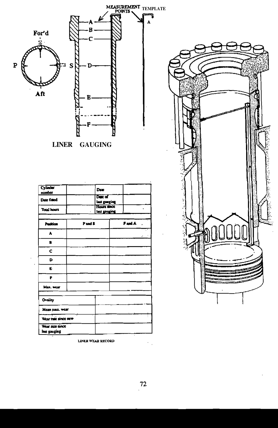
- Measurement Tooling: Use a calibrated internal cylinder micrometer mounted on an extension beam, verified against a master setting gauge at the same ambient temperature.
-
Measurement stations: Use the maker's template and specified heights; station count and location vary by liner design. Include the ring-reversal region, mid-stroke and the lower bore/port region where the manual specifies:
- Upper stations: capture wear at the piston-ring reversal and combustion-end region.
- Intermediate stations: show the bore profile through the ring travel.
- Lower stations: locate wear or distortion near ports and below the main ring-travel region where provided by the maker.
-
Two-Axis Measurement: At each vertical station, record measurements in two perpendicular planes:
- Fore-Aft (FA): Along the longitudinal axis of the ship.
- Second specified plane: take the perpendicular diameter at each station, using the maker's fore-aft/port-starboard orientation and datum.
Recording wear, ovality and serviceability
At each station, record both specified diameters and calculate bore growth from the documented original/reference diameter and out-of-roundness from the difference between perpendicular readings. Compare those values, the wear profile and any local damage with the limit table for that exact liner/engine. Do not use a generic percentage, running-hour rate or another engine's example as a condemnation value.
Why Maximum Wear Occurs at TDC of Top Ring
Four compounding factors converge simultaneously at the top dead centre reversal point of the top piston ring:
- Boundary Lubrication: Piston velocity slows to zero as the crank passes through TDC. The hydrodynamic oil wedge collapses completely, causing metal-to-metal asperity contact.
- Maximum Gas Pressure Behind Ring: Full peak combustion pressure (180–210 bar) enters the top ring groove, acting behind the ring and forcing it outward against the liner wall with maximum mechanical thrust.
- Maximum Metal Temperature: The top of the liner is closest to the combustion flame, operating at highest metal temperature where lubricant viscosity is lowest and oil film evaporates.
- Maximum Acid Concentration: Unburnt fuel and combustion gases are hottest and most reactive at the start of expansion.
5. In-Situ Inspection, Wave-Cut Finish & Liner Refurbishment
Replacing an 800 mm diameter cylinder liner costs over 150,000 USD in material and dry-dock labor. Proactive in-situ maintenance, honing, and surface profile re-conditioning can restore worn or scuffed liners to pristine operating condition.
In-Situ Scavenge Port Inspection
Every 250 to 500 hours (or during any port stay of sufficient duration), marine engineers perform an under-piston scavenge space inspection. By peering upward through the open scavenge air ports while turning the engine slowly on turning gear:
- Liner Wall Condition: Inspect for vertical abrasive scoring marks, brown lacquer varnish, or localized scuffing patches. Look for oily wetness; dry, glazed running surfaces indicate insufficient cylinder oil feed rate.
- Piston Rings: Check that all rings are free to move in their grooves (use a brass feeler gauge or wooden pry bar). Tap rings gently: a healthy ring emits a clear metallic ring; a broken ring gives a dull thud. Inspect for black gas blow-by soot marks across ring faces (indicating stuck or collapsed rings).
-
Scavenge Drain Residual Oil Analysis: Collect unburnt cylinder oil draining from the scavenge bottom drain cock. Measuring the iron content (Fe ppm) and residual Base Number (BN) provides immediate diagnostic feedback:
- Fe < 200 ppm, Residual BN > 15: Optimal lubrication regime.
- Fe > 500 ppm, Residual BN < 10: Severe cold corrosion active; increase cylinder oil feed rate or raise jacket water temperature.
- Fe > 1000 ppm: Catastrophic active scuffing; slow down engine immediately.
Wave-Cut Surface Machining vs Plateau Honing
A mirror-smooth, highly polished cylinder liner is an engine disaster. A glass-like bore cannot retain oil, leading to instantaneous oil film wiping and catastrophic adhesive scuffing ("bore polishing").
- Plateau Honing: Cross-hatch grinding creating microscopic grooves at a 40° to 50° angle. A secondary flat-honing pass shears off sharp peaks, leaving flat plateau bearing surfaces interspersed with deep microscopic oil retention valleys.
- Wave-Cut Machining: Modern MAN B&W cylinder liners feature a micro-undulated circumferential wave profile (depth ≈ 0.02 mm, pitch ≈ 0.2 mm) machined into the upper running surface. The wave crests support the piston rings while the troughs act as micro-reservoirs that hold cylinder oil under high combustion pressure, ensuring boundary lubrication survivability during low-load operation.
In-Situ Rig Honing Protocol
When a cylinder liner exhibits minor scuffing, cloverleaf wear, or ovality within allowable limits, a specialized pneumatic in-situ honing rig is mounted to the top of the cylinder block:
- The rig consists of expanding abrasive diamond-stone arms driven by a pneumatic motor that simultaneously rotates and strokes vertically inside the bore.
- Honing removes the hard, glazed surface skin, cuts away the top wear ridge, and restores the 45° cross-hatch micro-grooves.
- Following honing, the liner must be scrubbed with hot soapy water and nylon brushes (never cotton waste) to wash out abrasive diamond and iron grinding swarf from graphite pores, followed immediately by heavy manual coating with clean cylinder oil.
Practise this in the question bank
- Crankshaft / Bearing / Cylinder — 85 questions
Found a mistake, or something unclear?
Report it in a few seconds — it goes straight to the editors.
- Two-Stroke Structure — Frame, Tie Rods, Liner, Piston & Crosshead
- Marine Crankshafts — Builds, Bedplate, Chocks & Alignment
- Engine Bearings — Renewal, Crosshead to Thrust Block
- Camshaft Chain Drive, Hydraulic Tensioners & Timing Synchronisation
- Crosshead Assembly, Guide Clearances & Piston Rod Stuffing Box
- Cylinder Liner Wear, Calibration & Cold Corrosion
- Piston Crowns, Piston Rings & Thermal Mechanics
- Exhaust Valve Actuation, Air Spring Mechanics & Spindle Metallurgy
- Engine Bedplate Foundation, Holding Down Bolts & Epoxy Chocking
- Crankshaft Alignment, Web Deflections & Bearing Clearances