

Exhaust Valve Actuation, Air Spring Mechanics & Spindle Metallurgy
Complete guide to two-stroke exhaust valves: hydraulic pushrods, pneumatic air spring mechanics, Nimonic 80A metallurgy, hot corrosion, differential seat angles, and overhaul.
Operating Environment & Exhaust Valve Service Demands
In modern uniflow-scavenged two-stroke crosshead marine diesel engines, the exhaust valve assembly is arguably the most thermodynamically and mechanically stressed static-to-dynamic component in the entire power plant. Centrally situated in the cylinder cover, each cylinder relies on a single, massive exhaust valve to discharge hot combustion gases into the exhaust manifold and turbocharger turbine while maintaining an absolute, gas-tight seal against peak firing pressures exceeding 180 to 230 bar.
The Hostile In-Cylinder Environment
The valve operates under cyclical exposure to severe thermal, chemical, and mechanical forces repeated 70 to 120 times per minute under continuous transoceanic service:
- Extreme Thermal Cycling: During blowdown (when the valve opens approximately 40° to 60° before bottom dead center), supersonic gas flow engulfs the spindle disc and neck at temperatures between 500°C and 700°C. Within fractions of a second during the scavenge period, cool scavenge air at 35°C to 45°C sweeps across the valve face. This induces severe cyclic thermal gradient stresses across the disc and stem.
- Gas Dynamics & Erosive Velocity: High-velocity gas discharge exceeding 300 to 450 m/s past the initial cracking seat gap causes violent localized gas erosion. Any tiny combustion particulate, unburnt carbon flake, or fuel ash trapped on the landing face can trigger supersonic gas blow-by, leading to catastrophic channeling ("wire drawing") and seat burnout within dozens of hours.
- Vanadium-Sodium High-Temperature Hot Corrosion: Marine heavy fuel oils (HFO and low-grade VLSFO) contain soluble vanadium and sodium complexes. During combustion, vanadium oxidizes into vanadium pentoxide (V2O5), which combines with sodium oxides (Na2O) to form eutectic sodium-vanadyl-vanadates (such as Na2O·V2O4·5V2O5 and 5Na2O·V2O4·11V2O5). These eutectic slag mixtures have melting points as low as 535°C to 550°C. In molten state, this slag coats the valve head, fluxing and dissolving the protective chromium oxide (Cr2O3) layer on the metal surface, creating aggressive liquid-phase accelerated oxidation ("vanadium guttering").
- Cyclic Impact & Mechanical Shock: At engine speeds of 100 RPM, the valve cycles over 140,000 times per 24 hours. The landing impact of a spindle weighing 50 to 150 kg onto a stationary hardened valve seat ring demands controlled landing deceleration to prevent micro-chipping, seat hammering, and fatigue cracking of the valve spindle neck.
The Fundamental Thermal Stress Rule: finite element thermo-mechanical analysis reveals that in large two-stroke exhaust valves, thermal stress is 3 to 4 times greater than mechanical gas-pressure stress. The greatest thermal hoop stress develops along the transition radius of the valve neck, while the highest mechanical tensile stress occurs at the center of the flame face. Maintaining uniform circumferential temperature distribution is critical to prevent thermal warping.
Hydraulic Actuation: Cam-Driven vs Electronic Servo Systems
Modern two-stroke engines abandoned mechanical rocker arms, pushrods, and overhead camshaft linkages decades ago due to massive moving inertia, mechanical deflection, joint wear, and excessive noise. Instead, hydraulic actuation transmits opening force from the lower engine structure directly to the cylinder cover actuator.
1. Camshaft-Driven Hydraulic Pushrod (MAN B&W MC / MC-C Engines)
In conventionally cammed engines, actuation relies on a closed-circuit "hydraulic pushrod":
- Cam-Driven Actuator Pump: An exhaust cam mounted on the mid-level camshaft operates an actuator roller follower connected to a single-acting hydraulic pump piston. The cam profile dictates opening velocity, maximum lift, and the start of closing.
- High-Pressure Hydraulic Pipe: A double-walled, high-strength steel pipe filled with engine system lube oil connects the cam actuator pump to the hydraulic cylinder mounted atop the exhaust valve housing.
- Hydraulic Actuator Cylinder & Piston: As the camshaft turns, the cam lobe forces the actuator pump piston upward. Displaced hydraulic oil enters the cylinder atop the exhaust valve housing at 150 to 220 bar, driving the valve actuator piston downward. The actuator piston presses directly on the top end of the valve spindle, overcoming closing air spring pressure and forcing the valve open against cylinder pressure.
- Return & Oil Replenishment: As the cam follower rolls onto the base circle, oil flows back to the actuator pump under the driving force of the air spring. A non-return valve continuously feeds low-pressure system oil (approx. 4.0 to 5.5 bar) into the hydraulic circuit to replenish leakage past the piston rings, purge trapped air, and prevent cavitation. A venting valve on top of the actuator housing purges air pockets.
2. Electronically Controlled Actuation (MAN ME & WinGD RT-flex / X-Engines)
Modern "intelligent" electronically controlled two-stroke engines completely omit the exhaust camshaft, actuator roller followers, and mechanical camshaft drive gears.
| System Feature | MAN ME / ME-C Series (FIVA / ELVA) | WinGD RT-flex / X-Engines (VCU Rail Valve) |
|---|---|---|
| Hydraulic Power Source | Hydraulic Power Supply (HPS): engine-driven or electric axial piston swashplate pumps delivering 200–300 bar system oil. | Common Rail Servo Oil Pump Unit supplying servo oil rail manifold at 200 bar. |
| Control Valve Mechanism | FIVA (Fuel Injection & Valve Actuation) or ELVA/VIVA: high-speed proportional spool valve operated by linear torque motor. | Rail Valve: high-speed electro-hydraulic 3/2-way bi-stable poppet or spool valve. |
| Exhaust Valve Actuator | Hydraulic Cylinder Unit (HCU) mounted at each cylinder; proportional displacement controls lift profile. | Valve Control Unit (VCU) piston directly linked to exhaust valve spindle pushrod. |
| Variable Timing Flexibility | Fully independent variable exhaust valve opening (EVO) and closing (EVC) dynamically adjusted by Engine Control Units (ECUs). | Fully independent timing control across all speed/load profiles via WECS-9520 / UNIC control architecture. |
| Operational Advantages | Variable Compression Ratio: Deliberate early EVC during low-load operation raises effective compression ratio, preventing cold-corrosion and unburnt smoke. Reduces Part-Load SFOC by 2–4 g/kWh. | Tailors scavenge air retention during slow steaming; optimized blowdown timing matches turbocharger turbine pulse efficiency. |
Causes and Diagnostics of Exhaust Valve Knocking
Exhaust valve knocking or severe metal-to-metal hammering occurs when the hydraulic damping cushion fails or landing velocity exceeds design thresholds (typically >0.5 m/s). The chief operational causes fall into three distinct mechanical failure modes:
- Deficiencies in Hydraulic Oil Supply:
- Air in the oil (foaming): Caused by low lube oil sump level, air ingress at pump suction flanges, or failing supply non-return valves. Entrained air compresses elastomericly, causing lost motion during opening and collapsing cushioning upon landing.
- Low supply pressure: Pressure dropping below 4.0 bar starves the refill cycle, causing vacuum voids in the actuator chamber.
- Excessive oil temperature: Viscosity drops below acceptable operating thresholds (<10 cSt), causing extreme internal leakage through actuator piston clearances.
- Faults in the Air Spring System:
- Incorrect closing air pressure: Supply air pressure falling below 5.5 bar reduces valve acceleration, while excessive air pressure (>7.5 bar) slams the valve upward violently into the mechanical housing before hydraulic cushioning engages.
- Defective air spring drain / safety valve: Blocked drain line traps leaking hydraulic oil below the air piston, creating hydraulic lock that restricts full valve lift.
- Excessive High-Pressure Circuit Leakage:
- Worn piston rings or scoring in the hydraulic actuator cylinder.
- Maladjusted or worn throttle/cushioning cone needle valve.
- Punctured or leaking hydraulic non-return valve allowing HP oil to surge backward into the LP feed rail.
- Fractured or loose high-pressure pipe flange seals.
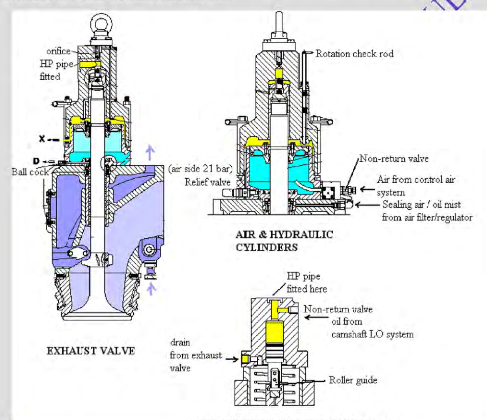
Pneumatic Air Spring Mechanics vs Helical Coil Springs
Many large slow-speed two-stroke engines use a pneumatic air spring to close the hydraulically opened exhaust valve. Other arrangements exist, so identify the system on the engine drawing before applying this description. Where fitted, the air spring avoids a large mechanical spring pack and provides a compressible closing force.
The Elimination of Helical Coil Springs
Mechanical steel coil springs have design and maintenance trade-offs on large, high-lift exhaust valves:
- Harmonic Resonance and Spring Surge: Every helical steel spring has a natural vibrational frequency (fn). As engine speeds and camshaft lift acceleration harmonics align with fn, high-amplitude torsional and axial waves travel back and forth along the spring wire ("surge"). This amplifies localized shear stresses beyond the endurance limit, leading to premature fatigue fracture.
- Catastrophic Drop Risk: When a mechanical spring fractured in an overhead valve pocket, the valve collets could dislodge, allowing the 80 kg valve spindle to drop directly into the cylinder space. The rising piston crown would crush the valve at 200 bar, devastating the cylinder cover, liner, and connecting rod.
- Linear vs Progressive Stiffness Limitations: A steel coil spring obeys Hooke's Law (F = k · x) where spring rate k is strictly constant. To ensure sufficient seating force against gas back-pressure when closed, excessive initial mechanical preload was mandatory. This exerted unnecessary high continuous loads on cam lobes and actuator bushings throughout the cycle.
- Weight and Bulk: Nested spring packs added 150 to 250 kg of reciprocating and static deadweight to each cylinder cover, complicating shipboard overhaul in tight crane clearances.
Thermodynamic Operating Principle of the Air Spring
The pneumatic air spring functions as a frictionless, variable-rate gas strut built directly into the lower housing of the exhaust valve:
- Air supply and charging: Regulated control air enters the air-spring chamber through the maker's specified pipework and non-return arrangement. Some published systems use about 7 bar, but the normal range and source are engine-specific; do not assume it is directly reduced from the starting-air receiver.
- Polytropic Compression Stroke: As the hydraulic actuator forces the valve spindle downward during opening, the air spring piston sweeps downward into the sealed air chamber. The trapped air is compressed polytropically (P · Vn = C, with n ≈ 1.3 to 1.35).
- Compression and restoring force: As the valve opens, its air-spring piston reduces the trapped volume and raises pressure; that pressure provides the closing force when hydraulic opening pressure is relieved. Peak pressure, volume ratio and valve travel are design-specific and must be taken from the maker's data.
- Progressive Restoring Force: Because the pressure escalates non-linearly with volume reduction, the air spring provides massive deceleration force precisely at bottom dead center to arrest downward spindle momentum, and maximum acceleration force to initiate rapid, crisp valve closing.
- Gentle Seating Force: As the valve returns toward the closed position, the air volume expands and pressure decays back to 6.0 bar. This delivers sufficient positive sealing force against scavenge manifold pressure without violently slamming the valve into the seat ring.
Air Spring Polytropic Closing Force Equation
Fclosing(x) = P(x) · Apiston = P0 · V0n (V0 − Apiston · x)n · Apiston
Where P0 = the engine's measured/specification charging pressure, V0 = initial chamber volume, Apiston = cross-sectional area of air piston, x = valve lift displacement, and n is the process exponent selected for the maker's calculation.
Pneumatic Safety and Cushioning Elements
- Safety relief and drains: Where fitted, the maker specifies relief setting and leakage drains. Hydraulic oil or condensate in the air-spring chamber can affect its working volume and response; investigate abnormal drain discharge and never change a relief setting outside the approved procedure.
- Bottom Oil Drain / Leakage Orifice: Positioned at the lowest point of the air chamber to drain oil and condensed moisture into the engine dirty oil drain tank. A spring-loaded drain valve or calibrated orifice ensures continuous purging. If this drain chokes, oil accumulation leads to hydraulic lock and severely restricted valve lift!
- Hydraulic cushioning: Depending on design, a damping feature controls valve landing and helps limit seat impact. Its clearances and adjustment are maker-controlled.
Low air-spring pressure and response
Control air supplies the force that returns the exhaust valve after hydraulic opening pressure is relieved. If air pressure is low or the supply is interrupted, the closing force and valve response can be impaired. The alarm, interlock, slowdown or shutdown response differs by engine control system. Treat an air-spring pressure alarm as a machinery fault: verify the indicated supply and leakage using the approved procedure, notify the bridge and chief engineer, and follow the maker's operating limits. Do not continue operation on the assumption that the valve will close normally.
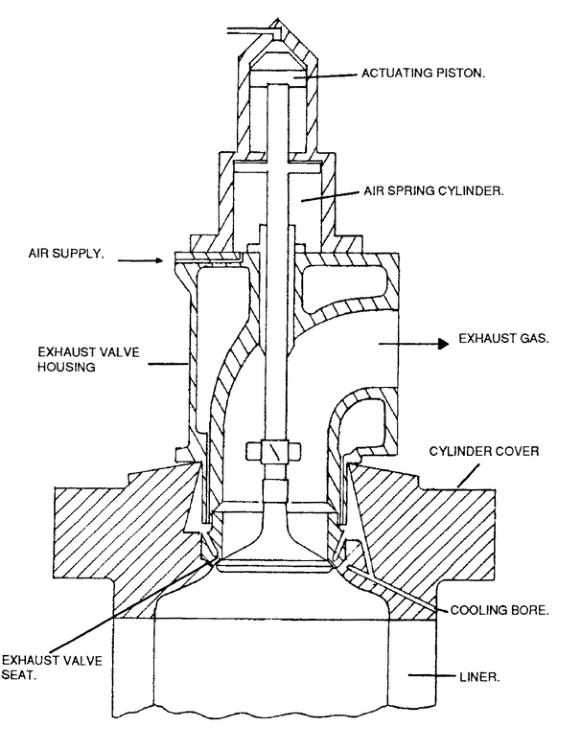
Valve Spindle Rotation: Aerodynamic Vanes vs Mechanical Rotators
Exhaust valves in internal combustion engines must rotate continuously in service. Operating a large marine diesel exhaust valve in a locked, non-rotating condition will cause seat failure and burn-through within a matter of hundreds of running hours.
The Four Critical Functions of Valve Rotation
- Equalization of Circumferential Temperature Gradients: Due to fuel injector spray asymmetry, localized scavenge swirl eddies, and proximity to the exhaust branch outlet, gas flow around the spindle head is non-uniform. Temperature differences across opposite sides of a stationary valve disc can reach 60°C to 100°C. This causes asymmetrical thermal expansion, warping the disc into an oval or "dished" contour that breaks gas sealing. Continuous rotation redistributes the thermal load, maintaining perfect circularity.
- Crushing and Removal of Ash Deposits: Molten vanadium and sodium fuel ashes stick to the landing face. As the valve rotates and lands, the microscopic relative movement and rotational momentum crush glassy ash crystals and sweep deposits clean before they fuse into solid slag.
- Elimination of Localized Hot-Spot Burnout: If a minor gas leak develops at one point on the circumference, rotation prevents concentrated high-velocity flame jetting on a single spot of the seat, stopping the runaway formation of burned gutters.
- Uniform Radial Wear Distribution: Friction and mechanical seating wear are distributed evenly around the entire 360° contact face instead of concentrating in one quadrant.
1. Gas-Driven Rotation Vanes (Two-Stroke Engines)
Modern two-stroke engines employ curved aerodynamic rotation wings (vanes) cast or welded directly onto the valve spindle stem immediately above the valve disc:
- Operating Principle: As the exhaust valve opens during blowdown, high-velocity exhaust gas (350–500 m/s) discharges past the spindle neck and impinges upon the angled vanes. The aerodynamic lift generated creates a strong tangential torque.
- Thrust Bearing Race: To allow the spindle to spin freely under high gas forces, a heavy-duty ball or roller thrust bearing assembly is interposed between the valve spring collar and the static casing. The valve spindle rotates at approximately 10 to 30 RPM under medium-to-full engine load.
- Load Dependency: Because rotational torque is derived from exhaust gas kinetic energy, rotation speed is proportional to engine load. At low loads (<25%), gas velocity drops, and spindle rotation may stop. Special synthetic grease or forced oil lubrication on the thrust bearing minimizes static friction.
2. Mechanical Positive Rotators: Rotocap vs Turnomat (Four-Stroke Engines)
In medium-speed four-stroke auxiliary and propulsion engines, exhaust gas velocities are insufficient to reliably drive vanes. Mechanical positive rotators built into the spring carrier are utilized:
| Parameter | Rotocap Mechanism | Turnomat Mechanism |
|---|---|---|
| Internal Architecture | Belleville disc spring washer resting on a circumferential race containing 6 to 10 steel ball bearings seated in inclined helical tracks with return coil springs. | Helical splines or cam track rollers engaging internal ratchet teeth with locking pawls. |
| Rotation Timing | Rotates as the valve OPENS. As rocker arm force compresses the valve spring, the increasing load flattens the Belleville washer. The washer lifts off the ball race, allowing the balls to roll down their inclined tracks, driving the spring carrier and spindle through 2° to 5° of rotation per stroke. | Rotates as the valve CLOSES. Rotation occurs during the landing stroke, creating positive relative sliding friction against the seat ring. |
| Primary Mechanical Benefit | Smooth rotation without dynamic friction against the seat face, minimizing abrasive scrubbing wear of the Stellite coating. | Aggressive mechanical scraping action that shears hard carbon deposits off the seat face during closure. |
| Operational Monitoring | Engineers apply a visible vertical paint stripe across the rotocap body and spindle top. Under a stroboscopic light (or visual check during running), positive rotation must be verified at every watch. Non-rotation requires immediate overhaul. | Visual index marks checked at idle and normal operating speeds. |
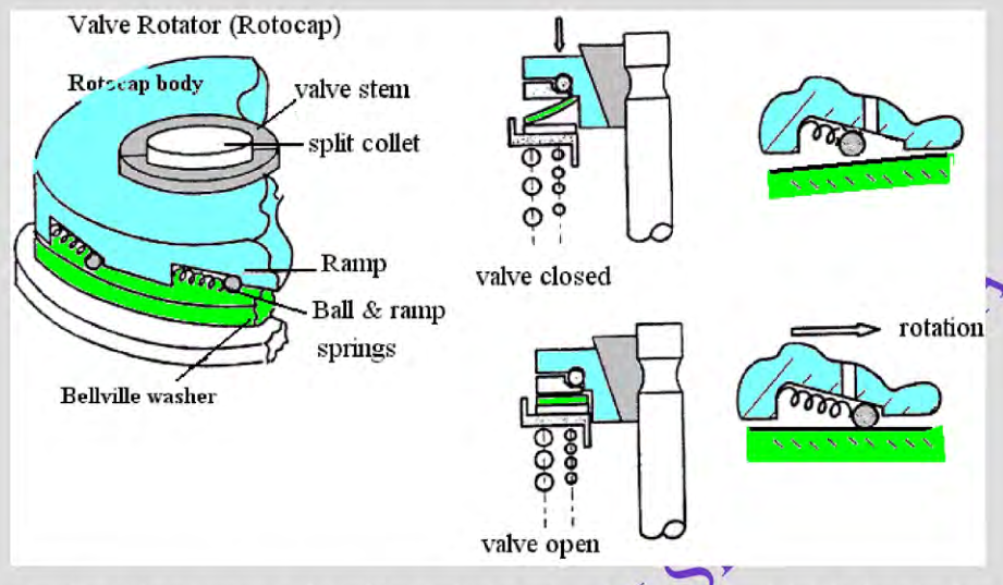
Exhaust Valve Metallurgy & High-Temperature Materials
The metallurgy of the exhaust valve spindle represents one of the pinnacle achievements in high-temperature marine materials engineering. The material must resist creep deformation at 750°C, withstand high-cycle mechanical fatigue from millions of seating impacts, and provide absolute chemical immunity to molten sodium-vanadium pentoxide hot corrosion.
Evolution of Valve Materials
- Martensitic Chromium Steels (Obsolete): Early engines used silicon-chromium steels (e.g., En52 / Silchrome). While cheap, they lost hardness rapidly above 500°C and suffered disastrous catastrophic oxidation when burning heavy fuel.
- Austenitic Stainless Steels (21-4N): Containing 21% Chromium, 4% Nickel, 9% Manganese, and 0.4% Nitrogen. These alloys offer decent hot tensile strength and form a passivating Cr2O3 surface layer, but remain vulnerable to vanadium attack above 540°C.
- Superalloys: Nimonic 80A (Modern Industry Benchmark): Forged precipitation-hardenable nickel-chromium-titanium alloy:
- Chemical Composition: ~70% Nickel (Ni), 19.5% Chromium (Cr), 2.4% Titanium (Ti), 1.4% Aluminum (Al), balance Iron and trace Cobalt.
- Precipitation Hardening: Intermetallic gamma-prime (γ' - Ni3(Ti, Al)) precipitates form uniformly within the austenitic nickel matrix, preventing dislocation movement and creep rupture up to 750°C.
- Immunity to Vanadium Eutectics: High nickel and chromium content forms a refractory, dense, adherent chromia-spinel oxide layer that resists dissolution by molten sodium vanadate slags.
- Forged One-Piece Construction: Modern large spindles are hot-die forged in a single piece, eliminating weld heat-affected zones in the high-stress neck radius.
- DuraSpindle (MAN B&W Advanced Hardfacing): A specialized engineered design where a forged heat-resistant steel spindle head is armored with a super-hard, highly alloyed welded layer across the entire combustion combustion bowl and seating face, delivering exceptional wear life exceeding 40,000 to 60,000 running hours.
Seat Face Hardfacing: Stellite Alloys
Because the valve spindle disc undergoes localized contact stresses up to 300 MPa against the seat ring, the contact face must be hardfaced with cobalt-based superalloys deposited via Plasma Transferred Arc (PTA) welding or laser cladding:
| Hardfacing Alloy | Key Composition | Mechanical Properties | Marine Application |
|---|---|---|---|
| Stellite 6 | Cobalt Base, 28% Cr, 4.5% W, 1.2% C | Hot hardness 38–42 HRC at 550°C; outstanding galling and cavitation erosion resistance. | Standard weld overlay for medium-speed four-stroke and two-stroke auxiliary valves. |
| Stellite 12 | Cobalt Base, 29% Cr, 8.5% W, 1.4% C | Higher tungsten carbide fraction; exceptional abrasive wear resistance under high mechanical contact pressures. | Heavy-duty uniflow exhaust valve seat inserts subject to high-ash residual fuel combustion. |
| Inconel 625 / 718 | Nickel-Chromium-Molybdenum-Niobium | High yield strength (up to 1100 MPa), exceptional thermal fatigue resistance without brittle carbide phase transformation. | Laser-clad valve spindle discs in extreme slow-steaming, high-pressure common rail engines. |
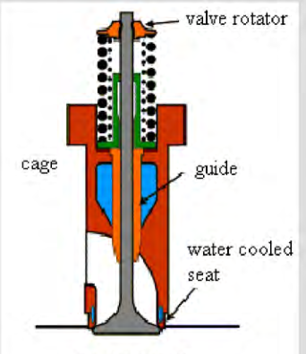
Bore-Cooled Valve Seat Ring & Differential Contact Geometry
Even the most advanced metallurgy will rapidly fail if metal temperatures are allowed to cross the critical threshold of 450°C to 500°C where vanadium slag liquefies. To maintain thermal integrity, modern engines utilize a separate, replaceable, bore-cooled valve seat ring.
Bore-Cooling Fluid Mechanics
Cast or forged from alloyed molybdenum-chromium steel, the valve seat ring incorporates precision-drilled cooling water passages:
- Geometry: A series of interconnected tangential and radial cooling holes are drilled diagonally through the ring body, passing within 10 to 15 mm of the actual valve seating landing surface.
- Coolant Circulation: Treated low-temperature jacket fresh water enters the bottom of the seat ring at 75°C to 80°C, circulates at high velocity (over 2.0 m/s to prevent localized nucleate boiling), and discharges into the cylinder cover jacket cooling gallery.
- Thermal Results: Bore cooling slashes the seat surface metal temperature from over 550°C down to 300°C to 350°C under 100% engine MCR! Because this operating temperature is more than 180°C below the melting point of sodium-vanadium eutectics, fuel ash hits the seat as a dry, non-corrosive solid powder that cannot weld to or chemically corrode the metal.
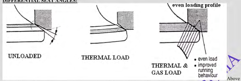
Differential Contact Angles (Thermal Distortion Compensation)
One of the most frequent examination questions in marine engineering relates to the differential angle machined between the exhaust valve spindle face and the valve seat ring.
Warning — Why Aren't the Angles Machined Identically? If the valve spindle and seat ring were both ground to exactly the identical angle (e.g., exactly 30°00' each) in the cold workshop state, the valve would leak violently under full engine load and burn out rapidly!
The thermodynamic explanation lies in radial and axial thermal expansion gradients:
- Thermal "Tuliping" / Dishing: The bottom combustion face of the valve spindle head is exposed to 600°C gas, while the upper face is cooled by scavenge air and the stem is cooled by the air spring. The bottom face expands significantly more than the top face. This severe vertical temperature gradient forces the rim of the valve disc to curl downward and outward—a distortion known as "tuliping".
- Cold Geometry (Inner Edge Contact): To compensate for this distortion, the valve seat ring is ground to exactly 30°00', while the valve spindle disc is ground slightly steeper to 30°30' to 30°45' (a differential mismatch of 30 to 45 angular minutes). In the cold state, contact occurs exclusively as a narrow line at the inner circumference of the seat.
- Hot Running Condition (Full Planar Contact): When the engine reaches normal running temperature and peak firing pressure (180+ bar) bears down upon the valve disc, the thermal curling and elastic deformation flatten the spindle disc outwards. The angular mismatch vanishes, establishing a 100% full-width, perfectly parallel planar contact across the entire seat width. Seating pressure is distributed uniformly, guaranteeing a hermetic gas seal and maximizing conductive heat transfer from the spindle to the water-cooled seat ring.
Overhaul Protocols, Measurements & Troubleshooting Matrix
The exhaust valve overhaul schedule is typically set between 8,000 and 16,000 running hours (or up to 24,000 to 32,000 hours for modern DuraSpindle assemblies). Rigorous procedural adherence prevents in-service disasters.
Step-by-Step Overhaul Procedure
- Pre-Dismantling Safety & De-energization: Isolate starting air and control air supplies to the cylinder unit. Open indicator cocks and engage the turning gear. Bleed hydraulic oil pressure from the actuator circuit and confirm that the air spring pressure gauge reads exactly zero. Lock out the engine remote control system.
- Dismantling & Rigging: Disconnect the double-walled high-pressure oil line, air supply pipe, cooling water flexible jumper hoses, and leakage drain lines. Mount the specialized lifting bracket to the exhaust valve casing. Using the engine room crane, withdraw the complete valve assembly vertically clear of the cylinder cover and land it onto the dedicated maintenance overhaul stand.
- Decompressing the Air Spring: Fasten the specialized hydraulic spring tensioner or central compression screw tool onto the spindle top. Compress the air spring slightly to relieve collet wedge tension. Remove the two-piece conical safety clamping collets (keeper pieces). Slowly relax the compression tool to release all residual spring energy before disassembling the upper hydraulic actuator and air piston.
- Cleaning & Non-Destructive Testing (NDT): Clean the spindle disc and seat using soft brass wire brushes or walnut-shell blasting (never use aggressive grinding wheels or chisels that notch the surface). Perform a meticulous Dye Penetrant Inspection (DPT) across the entire landing seat face, the neck fillet transition radius, and the bottom combustion center. Inspect specifically for:
- Radial thermal fatigue cracks spreading from the seat face inward.
- Guttering channels caused by high-temperature blow-by.
- Dishing (plastic concave deformation of the lower disc face).
- Critical Metrology & Dimensional Checks:
- Spindle Straightness (Runout): Mount the spindle on V-blocks or in a lathe. Position a dial test indicator (DTI) along the stem and rim. Maximum permissible radial runout along the spindle stem is typically <0.05 mm. A bent spindle must be scrapped immediately; attempting to straighten a Nimonic spindle introduces severe micro-cracking.
- Spindle-to-Guide Radial Clearance: Measure the internal diameter of the spindle guide bushing at top, middle, and bottom using an inside micrometer. Measure spindle stem outside diameter with an external micrometer. Maximum clearance must not exceed 0.35 to 0.45 mm (nominal clearance approx. 0.15 to 0.22 mm). Excessive clearance leads to spindle cocking, guide bell-mouthing, and severe seat landing misalignment.
- Air Piston & Hydraulic Rings: Measure piston ring end gaps (butt clearance) and ring vertical side clearances in grooves. Replace all piston rings, scraper packings, and rubber O-rings unconditionally at every overhaul.
- Burn-off / Grind-off Gauging: Measure the remaining height of the valve spindle head rim and seat width using the manufacturer's profile template gauge. Once the hardfacing layer has been reduced past the discard limit line, the spindle must be sent ashore for automated PTA re-cladding or scrapped.
- Reconditioning: Grinding vs Turning:
- Never turn Nimonic 80A or Stellite with conventional lathe tools—the extreme work-hardening characteristics cause tool chatter, surface tearing, and micro-stress fractures.
- Use a specialized portable pneumatic/electric valve seat grinding machine mounted rigidly on the valve casing. Set the grinding head angle with extreme precision using the calibrated protractor setting (e.g., exactly 30°00' for the seat and 30°30' for the spindle).
- After grinding, verify contact quality by applying a micro-thin smear of Prussian Blue engineer's marking dye. Cold blueing must show a distinct, unbroken, continuous contact ring around the inner circumference. Light lapping with fine carborundum paste may be completed to ensure roundness, followed by meticulous solvent washing.
Exhaust Valve Troubleshooting Matrix
| Observed Symptom | Probable Root Causes | Immediate Corrective Action |
|---|---|---|
| High exhaust temp on single unit + drop in Pmax and Pcomp | Exhaust valve gas leakage / blow-by. Seat burned by vanadium guttering or jammed open by foreign ash particulate. | Reduce engine speed/load immediately to prevent catastrophic seat washout. If temperature exceeds 480°C–500°C, stop engine, cut off fuel injection to affected cylinder, and replace valve assembly with spare. |
| Severe valve knocking / hammering during closure |
|
Purge air via top actuator venting cock. Verify actuator supply oil pressure and temperature. Check closing air pressure regulator (set to 6.0–6.5 bar). Overhaul actuator cushioning if knocking persists. |
| Valve fails to open or opens with restricted lift |
|
Clear air spring safety drain line. Inspect hydraulic pushrod actuator pump. Switch engine control to backup channel or replace electronic pilot valve. |
| Air spring safety relief valve blowing continuously |
|
Measure closing air supply pressure. Check air spring drain collector for excessive oil carry-over. If oil discharge is heavy, replace actuator shaft scraper seals. |
| Spindle fails to rotate in service |
|
Clean vanes during next port stay. Flush thrust bearing with cleaner/lubricant. If spindle remains stationary at >50% load, schedule immediate valve replacement to avoid thermal warping. |
Practise this in the question bank
- Turbocharger / Supercharger — 16 questions
Found a mistake, or something unclear?
Report it in a few seconds — it goes straight to the editors.
- Two-Stroke Structure — Frame, Tie Rods, Liner, Piston & Crosshead
- Marine Crankshafts — Builds, Bedplate, Chocks & Alignment
- Engine Bearings — Renewal, Crosshead to Thrust Block
- Camshaft Chain Drive, Hydraulic Tensioners & Timing Synchronisation
- Crosshead Assembly, Guide Clearances & Piston Rod Stuffing Box
- Cylinder Liner Wear, Calibration & Cold Corrosion
- Piston Crowns, Piston Rings & Thermal Mechanics
- Exhaust Valve Actuation, Air Spring Mechanics & Spindle Metallurgy
- Engine Bedplate Foundation, Holding Down Bolts & Epoxy Chocking
- Crankshaft Alignment, Web Deflections & Bearing Clearances