

Electronic Cylinder Lubrication: Alpha Lubricator & Pulse Systems
Master marine cylinder lubrication: MAN Alpha lubricator, WinGD PLS, SIP swirl injection, feed rate calculation, BN matching, and scuffing prevention.
1. Cylinder Lubrication Philosophy & Mechanical Lubricator Limitations
Unlike four-stroke trunk piston engines—where cylinder liners are splash-lubricated by oil thrown from the crankcase—large two-stroke crosshead marine diesel engines isolate the combustion chamber completely from the crankcase by means of a transverse diaphragm and piston rod stuffing box. Consequently, the cylinder liner and piston rings must be lubricated on a once-through, total-loss basis: oil injected onto the liner is burned during combustion, scraped down into the scavenge air space, or carried out with the exhaust gas.
The Dual Mission of Marine Cylinder Oil
Cylinder lubricating oil (CLO) must accomplish two conflicting physical and chemical objectives simultaneously:
- Tribological Separation (Physical Duty): Maintain a continuous, elastohydrodynamic and boundary lubricant film between the reciprocating piston rings and the cast iron liner wall under peak combustion pressures exceeding 200 bar and surface temperatures reaching 250°C, preventing adhesive scuffing, micro-welding, and excessive abrasive wear.
- Acid Neutralization (Chemical Duty): Heavy fuel oils contain significant sulfur (up to 3.5% in HSFO, up to 0.50% in VLSFO). Combustion oxidizes sulfur to SO2 and SO3, which combines with moisture to condense as highly concentrated sulfuric acid (H2SO4) on the liner walls. The cylinder oil must carry an alkaline chemical reserve—quantified by its Base Number (BN), ranging from 15 to 140 mg KOH/g—to continuously neutralize acid before it can corrode the cast iron matrix.
Limitations of Traditional Mechanical Lubricators
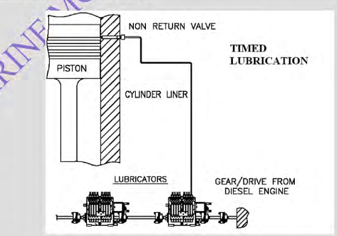
For nearly a century, engines relied on mechanical lubricators (such as the classic IVO or Hans Jensen mechanical boxes) driven by mechanical linkages or chains from the engine camshaft:
Mechanical Lubricator Shortcomings vs Modern Engine Demands
| Operational Parameter | Mechanical Lubricator (Traditional) | Electronic Timed Lubricator (Alpha / PLS) |
|---|---|---|
| Injection Timing | Untimed: Piston-displacement delivery. Oil discharges continuously into the cylinder regardless of piston position. | Millisecond-Precision Timed: Injected directly into the passing piston ring pack on the upward stroke. |
| Oil Wastage | Over 50% to 70% of injected oil is wasted: discharged into open combustion gas (burned unproductively) or scraped down into scavenge drains. | Negligible wastage. Up to 90% of oil is trapped and spread by the piston rings across the upper stroke. |
| Load Dependency | Rough mechanical linkages; cannot respond dynamically to fuel sulfur variations or low-load slow steaming. | Fully computerized; dynamically calculates feed rate based on engine load (MEP), RPM, and fuel sulfur content (ACC). |
| Specific Oil Consumption | High: 1.2 to 1.6 g/kWh (costing over 200,000 USD/year on a container vessel). | Low & Optimized: 0.60 to 0.85 g/kWh (saving up to 40% in lubricant consumption while reducing wear). |
2. The MAN B&W Alpha Lubricator System Architecture
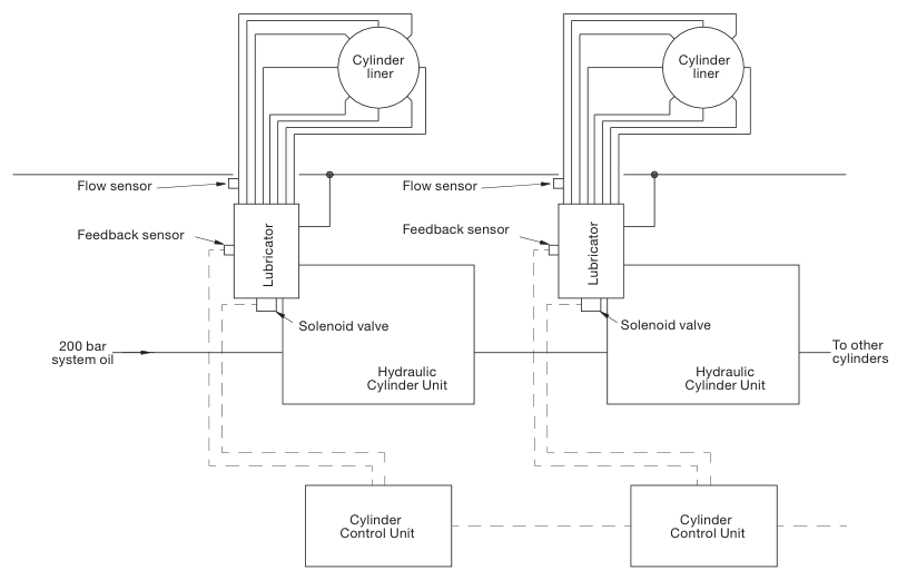
The MAN B&W Alpha Lubricator System is an electronically controlled, hydraulically actuated pulse injection system that replaced mechanical lubricators across all modern MC and ME series two-stroke engines. It delivers microscopic, high-pressure pulses of cylinder oil directly into the piston ring pack at the exact millisecond the piston rings pass the lubricator quills on the upward compression stroke.
System Components & Hydraulic Circuit
Operational Sequence of the Alpha Lubricator
- Hydraulic Power Supply (HPS): Electric motor-driven gear pumps draw engine system oil from the main sump, pressurizing it to 40 to 50 bar. The pressurized oil passes through a fine 10 µm duplex filter and is stored in nitrogen-charged diaphragm accumulators adjacent to each lubricator block.
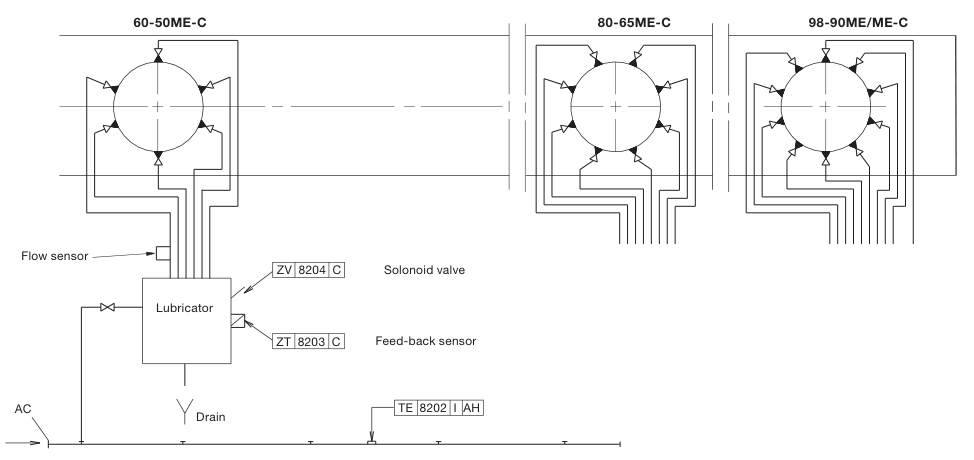
- Lubricator Block Architecture: Each cylinder is fitted with an independent lubricator block containing a centralized hydraulic servo piston that drives 5 to 8 small dosing plungers (one per lubrication quill). A high-speed 24V DC solenoid valve controls hydraulic oil entry.
- Crankshaft Position Trigger: Two redundant magnetic/optical shaft encoders mounted on the flywheel continuously feed exact crankshaft angle and RPM to the Master Control Unit (MCU).
- The Injection Pulse: As the piston travels upward on compression, the MCU energizes the solenoid valve at an exact, programmed crank angle (typically when the top piston ring has just crossed the quill line). The 45 bar servo oil drives the hydraulic piston, causing all dosing plungers to stroke simultaneously.
- Distribution into Ring Pack: The plungers force a precise, calibrated micro-volume (approx. 0.15 to 0.20 cm³ per quill) past spring-loaded ball non-return valves in each quill. The oil enters the space between the 1st and 2nd or 2nd and 3rd piston rings. As the piston completes its upward stroke, the rings drag and spread the oil film upward toward TDC, where boundary protection and acid neutralization are urgently required.
- Return & Feedback: De-energizing the solenoid valve allows springs to return the plungers, drawing fresh cylinder oil from the day tank. An inductive proximity switch (feedback sensor) confirms full plunger stroke on every injection pulse; failure to stroke triggers an immediate slow-down alarm.
3. WinGD Pulse Lubricating & The Swirl Injection Principle (SIP)
While MAN B&W focuses on injecting oil directly between the passing piston rings, WinGD (Wärtsilä/Sulzer) developed alternative philosophies: the Pulse Lubricating System (PLS) and the patented Swirl Injection Principle (SIP) pioneered by Hans Jensen Lubricators.
The Swirl Injection Principle (SIP)
Traditional quills discharge liquid oil directly onto the liner wall, relying on piston rings to drag oil circumferentially. This produces uneven oil distribution and leaves dry zones that trigger cloverleaf wear.
How the Swirl Injection Principle Operates
- High-Pressure Atomizing Nozzles: Instead of simple open holes, SIP quills incorporate special spray nozzles operating at high injection pressure (35 to 40 bar).
- Injection Timing: The oil mist is sprayed into the cylinder during the scavenging period, well before the piston arrives at the quills.
- Aerodynamic Deposition: The upward uniflow scavenge air possesses intense helical angular velocity (swirl). When atomized oil micro-droplets are sprayed horizontally into the vortex, the rotational velocity creates massive centrifugal acceleration that flings the droplets outward.
- Result: The droplets deposit evenly across the entire 360° internal circumference of the liner wall before the piston rises, forming a perfectly uniform lubricating and neutralizing layer that completely eliminates dry cloverleaf zones.
4. Feed Rate Optimization & Adaptive Cylinder Control (ACC)
Controlling cylinder oil feed rate is an uncompromising financial and operational balancing act:
- Under-Lubrication (Feed Rate Too Low): Results in rapid cold corrosion, adhesive scuffing, broken piston rings, blow-by, and liner replacement within 5,000 to 10,000 hours.
- Over-Lubrication (Feed Rate Too High): Wastes thousands of dollars of expensive oil, fouls scavenge spaces and turbochargers, and—critically—causes unreacted alkaline calcium carbonate additives to bake into hard calcium ash crusts on piston top lands. These hard crusts wipe away the oil film, polishing the liner bore and precipitating catastrophic scuffing.
The Feed Rate Formula & Baseline Calculations
Specific cylinder oil consumption is expressed in grams per kilowatt-hour (g/kWh):
Specific Feed Rate (g/kWh) = Daily Consumption (kg/24h) × 1,000Average Engine Power (kW) × 24 hours
Historical vs Modern Target Feed Rates:
- Older mechanical lubricators: 1.20 to 1.60 g/kWh.
- Running-in new liners/rings: 1.20 to 1.50 g/kWh for the first 500 hours.
- Modern electronically controlled engines: 0.60 to 0.85 g/kWh under normal sea cruising.
The Adaptive Cylinder Oil Control (ACC) Algorithm
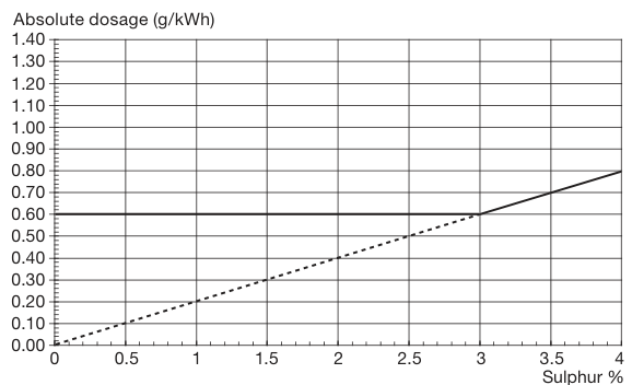
Engineered by MAN B&W, the ACC algorithm dynamically adjusts the specific cylinder oil dosage proportionally to the sulfur percentage present in the fuel:
Cylinder Oil Feed Rate (g/kWh) = ACC Factor × Fuel Sulfur (%)
Where:
- ACC Factor: Typically set between 0.20 and 0.26 g/(kWh · %S) for standard BN 100 oil, or higher for lower BN oils.
- Minimum Feed Rate Floor: Regardless of low sulfur content, the feed rate must never drop below a mechanical minimum hydrodynamic floor (typically 0.60 g/kWh) to prevent boundary lubrication failure.
Practical Feed Rate Calculation Examples (MAN 7S60ME-C8)
Engine Power: 14,000 kW | ACC Factor: 0.22 g/(kWh · %S) | Oil: BN 100
Case A: Burning High Sulfur HFO (2.7% S)
Feed Rate = 0.22 × 2.7 = 0.594 g/kWh → Clamped to minimum floor: 0.60 g/kWh.
Daily Consumption = (14,000 kW × 24 h × 0.60 g/kWh) / 1,000 = 201.6 kg/day (~225 litres/day).
Case B: Severe Low-Load Operation Burning 3.2% S HFO
To counteract low-load cold corrosion, ACC Factor elevated to 0.26:
Feed Rate = 0.26 × 3.2 = 0.832 g/kWh.
Daily Consumption = (14,000 kW × 24 h × 0.832 g/kWh) / 1,000 = 279.5 kg/day (~312 litres/day).
5. Scavenge Drain Oil Sampling & Condition Monitoring Matrix
Modern marine engineering practice prohibits blindly relying on electronic settings. The true operational health of the cylinder liner and piston rings must be validated through regular Scavenge Drain Residual Oil Analysis (also known as scrape-down oil analysis).
Sampling Protocol
- The engine must be operating at steady cruising load for at least 1 to 2 hours prior to sampling.
- Open the cylinder scavenge bottom drain valve and purge the drain line for 30 seconds to flush stagnant sludge.
- Collect a clean 250 ml sample in a specialized container from each cylinder independently.
- Test shipboard immediately using digital test kits or dispatch to ashore laboratories for Inductively Coupled Plasma (ICP) spectrometry.
Key Diagnostic Parameters
-
Residual Base Number (Residual BN): Measures the alkaline reserve remaining in the unburnt oil scraped down into the scavenge space.
- Target Range: 15 to 25 mg KOH/g. This proves that sufficient alkalinity was present to neutralize all sulfuric acid, leaving a small safety margin.
- Residual BN < 10: Acid neutralization failed! Active cold corrosion is occurring. Action: Increase feed rate immediately or switch to higher BN oil.
- Residual BN > 40: Over-lubrication! Unreacted calcium carbonate is precipitating on piston crowns. Action: Reduce feed rate.
-
Total Iron Content (Fe ppm): Measures the total quantity of worn metal:
- Fe < 150 ppm: Excellent running conditions; normal mechanical wear.
- Fe 200 – 400 ppm: Moderate corrosive or abrasive wear; monitor closely.
- Fe > 500 ppm: Critical alarm! Severe corrosive wear or micro-scuffing active.
- Magnetic Iron (PQ Index / Particle Quantifier): Measures large ferromagnetic debris particles (> 5 µm) resulting from abrasive cutting or adhesive scuffing, distinguishing mechanical abrasive tearing from microscopic chemical corrosion (which dissolves as non-magnetic iron salts).
Engine Room Action Matrix Based on Scavenge Drain Analysis
| Residual BN (mg KOH/g) | Iron Content (Fe ppm) | Liner Running Condition | Immediate Corrective Action Required |
|---|---|---|---|
| 15 – 30 | < 150 | Optimal: Perfect balance of acid neutralization and hydrodynamic film. | Maintain current feed rate and ACC factor. No adjustment. |
| < 10 | 300 – 800 | Severe Cold Corrosion: Acid dew point condensation; alkaline reserve exhausted. | Step-up feed rate by 0.15 g/kWh immediately; raise jacket water cooling temp to 92°C; inspect liner surface. |
| > 40 | < 100 | Over-Lubrication: Excess oil wasted; risk of calcium ash bore polishing. | Reduce feed rate incrementally by 0.05 g/kWh per week; inspect piston crown lands for ash crusts. |
| > 25 | > 600 (High Magnetic) | Catastrophic Scuffing / Cat Fine Ingress: Severe abrasive or adhesive tearing. | Check fuel purifier Al+Si levels; perform scavenge port inspection for ring seizure; run in-situ honing if scuffed. |
Practise this in the question bank
- Lubrication System — 31 questions
Found a mistake, or something unclear?
Report it in a few seconds — it goes straight to the editors.