

Crankshaft Alignment, Web Deflections & Bearing Clearances
Master marine crankshaft alignment: dial indicator web deflections, calculation formulas, deflection curve interpretation, bridge gauge clearances, and tri-metal bearings.
1. Engineering Principles of Crankshaft Alignment & Elastic Flexure
In marine slow-speed two-stroke crosshead engines, a multi-throw crankshaft weighing upwards of 150 to 300 tonnes is not an infinitely rigid structural beam. Under the influence of its own massive self-weight, the oscillating mass of the running gear (pistons, crossheads, connecting rods), explosive cylinder gas pressures (peak firing pressures exceeding 150–200 bar), and propeller shaft reaction moments, the crankshaft behaves as a continuous, elastically flexible beam supported at multiple discrete points by the bedplate main bearings.
Perfect geometric collinearity between all main bearing centerlines is impossible to maintain permanently under operating conditions. Deviations occur continuously due to:
- Uneven Main Bearing Wear: Unequal hydrodynamic film thickness, particulate abrasion, or micro-wiping in adjacent bearing shells causes one journal center to settle lower than its neighbors.
- Bedplate & Hull Girder Deflection: The ship's double bottom hull girder flexes dynamically in response to sea states, wave bending moments, and changing cargo loading conditions (hogging, sagging, ballast vs laden condition). Because the engine bedplate is bolted directly to the tank top through holding-down bolts and chocks, hull flexure directly induces bedplate curvature.
- Thermal Gradients: Differential expansion between the forward, mid, and aft sections of the bedplate occurs between cold harbor condition (ambient sea temp) and full operating temperature (lube oil at 45°C, jacket water at 85°C).
- Loose or Damaged Holding-Down Bolts / Chocks: Yielding of foundation bolts or fretting / crushing of cast iron or epoxy chocks allows localized bedplate relaxation.
When adjacent main bearings are out of alignment, the crank throw spanning between them is subjected to cyclic alternating bending stresses during every crankshaft revolution. As the crankpin rotates from Top Dead Centre (TDC) to Bottom Dead Centre (BDC), the parallel distance between the inner surfaces of the crank webs continuously breathes—either opening outward or closing inward. If this alternating flexure exceeds the endurance limit of the crankshaft steel, high-cycle fatigue cracking initiates at the crankpin and journal fillet radii, culminating in catastrophic crankshaft fracture.
2. Semi-built crankshaft construction and shrink fits
How a semi-built crankshaft is assembled
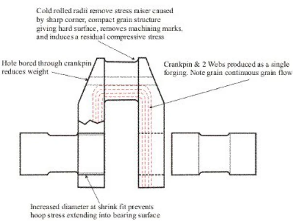
On many large slow-speed crosshead engines, each crank throw—its two webs and crankpin—is made as one forging, and separately forged main journals are shrink-fitted into the web bores to assemble the shaft. This gives the throw continuous grain flow around the crankpin while allowing the long shaft to be manufactured from manageable sections. Other designs and manufacturing details exist, so identify the arrangement on the engine drawing before describing it as universal.
In a shrink fit, the parts are brought to the specified temperature condition to create temporary assembly clearance, positioned to the prescribed alignment, then allowed to equalize so the interference fit transmits torque. The interference allowance and assembly temperatures are design-specific: do not apply a memorized ratio to a different crankshaft. Inspection for slip, fretting or cracks and any repair are specialist maker-controlled work.
3. Web Deflection Measurement Setup & The 5-Point Angular Cycle
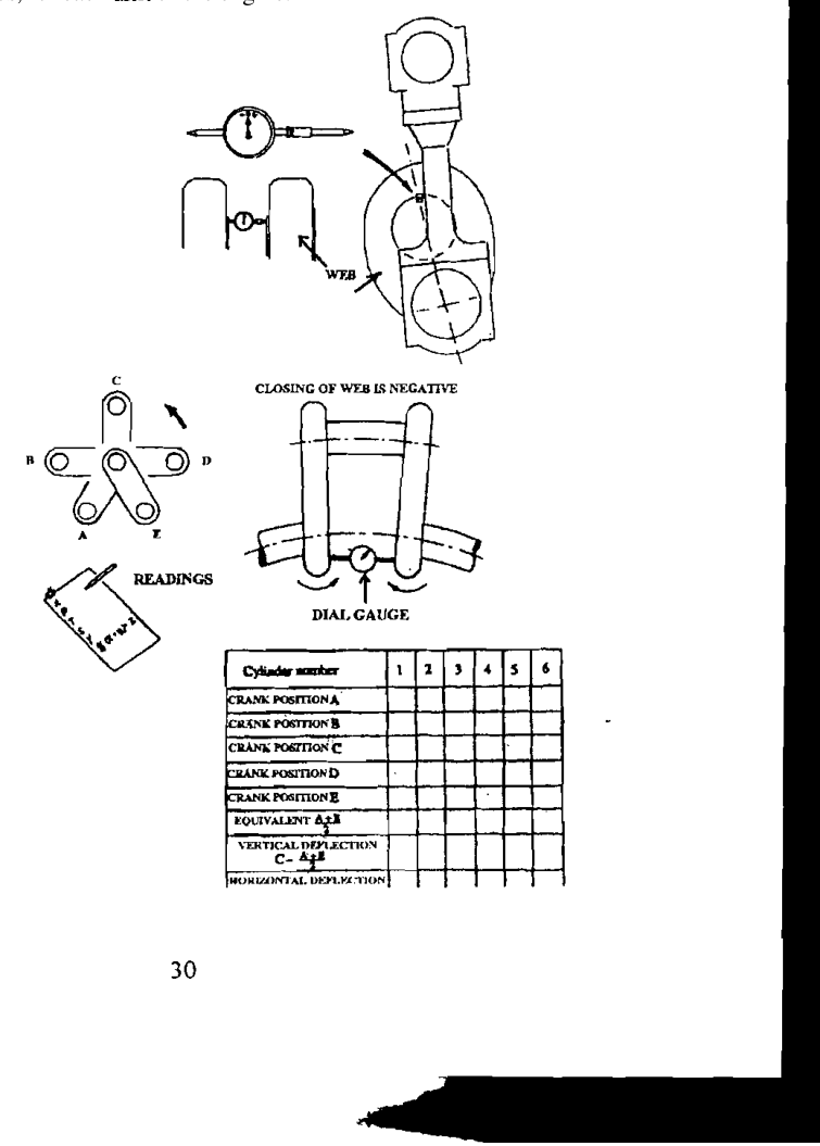
Crankshaft alignment is evaluated without dismantling the engine by measuring the breathing (expansion and contraction) of the crank webs across 360° of rotation using a sensitive dial test indicator (DTI) calibrated in hundredths of a millimeter (0.01 mm).
Gauge Positioning & Pre-Conditioning
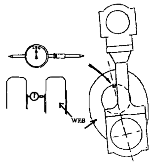
- Locating Punch Marks: Engine builders machine small conical center-punch depressions into the inner faces of each pair of crank webs at a standardized radial distance (typically at half stroke, or on the web periphery opposite the crankpin). The spring-loaded conical tips of the deflection gauge extension rod fit precisely into these depressions.
- Zeroing & Friction Check: Mount the gauge and rotate it lightly by hand to verify that the conical tips are seated firmly in the punch centers without binding. Pre-compress the gauge spring to approximately mid-travel (typically 3–5 mm) and rotate the dial bezel to set the initial needle to zero (or an agreed reference offset such as +10 or 0).
- Connecting Rod Clearance: When the crankpin is near Bottom Dead Centre, the connecting rod passes directly between the crank webs. A single Bottom Dead Centre reading is physically impossible because the connecting rod body would foul and crush the gauge. Therefore, two readings are taken on either side of BDC: BDC Port (BDCP) and BDC Starboard (BDCS), with the connecting rod angled just clear of the gauge.
The 5-Point Measurement Sequence
Before measurement, secure against starting and follow the ship's crankcase-entry and turning-gear procedures. Record vessel loading/draught and the engine's thermal state so later readings can be compared under like conditions. Fit the calibrated gauge at the maker's punch marks and turn in the specified direction; unload the turning-gear drive as directed before each reading. Record every prescribed angle, especially the two clear-of-rod positions on either side of BDC. The exact points and sign convention must follow the engine manual.
| Position | Crank Angle (θ) | Connecting Rod Status & Reading Notation |
|---|---|---|
| BDC Port (BDCP) | Approx. 210° (30° past BDC in Ahead direction) | Connecting rod has cleared the gauge toward Starboard. Gauge zero is verified or initialized here. |
| Port (P) | 270° (Horizontal crankpin facing Port) | Horizontal alignment component; reflects lateral bedplate displacement or side-thrust wear. |
| Top Dead Centre (TDC) | 0° / 360° (Vertical crankpin at top) | Peak vertical bending moment position; primary indicator of bearing elevation differential. |
| Starboard (S) | 90° (Horizontal crankpin facing Starboard) | Horizontal alignment component; compared against Port to compute lateral bedplate warping. |
| BDC Starboard (BDCS) | Approx. 150° (30° before BDC in Ahead direction) | Connecting rod approaches gauge from Port side. Final reading before rod fouls gauge. |
4. Mathematical Evaluation & Deflection Curve Plotting
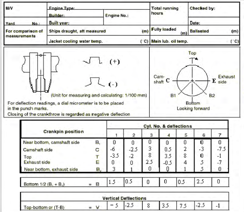
Once the 5 readings are recorded for each cylinder unit, they are converted into standardized vertical and horizontal deflection values. Because the true Bottom Dead Centre (BDC) reading cannot be taken directly, it is mathematically estimated as the arithmetic mean of the two adjacent readings:
Virtual Bottom Dead Centre (BDCcalc)
BDCcalc = BDCP + BDCS2
Where BDCP is the reading at BDC Port and BDCS is the reading at BDC Starboard.
Vertical Deflection (ΔV)
ΔV = TDC - BDCcalc = TDC - BDCP + BDCS2
ΔV represents the net vertical breathing of the webs. A positive value indicates the webs open wider at TDC than at BDC; a negative value indicates the webs close inward at TDC.
Horizontal Deflection (ΔH)
ΔH = P - S
Where P is the reading at Port and S is the reading at Starboard. Always verify against the engine maker's convention and alignment chart, as sign conventions and gauge orientation may differ.
Plotting the Crankshaft Alignment Curve
Individual unit deflections indicate local bending, but to assess the overall profile of the crankshaft along the engine bedplate, engineers plot the Crankshaft Alignment Curve:
Use the maker's prescribed conversion from measured web spread to shaft-line/bearing interpretation. Deflection curves are comparative diagnostic records, not a standalone map that identifies a single worn bearing. Plot against the reference condition and consider vessel draft/loading, temperature, gauge position, bearing clearances and previous measurements before deciding corrective action.
The engine maker's deflection chart defines how readings are plotted and compared. Do not derive a bearing-elevation curve by cumulatively summing raw web-deflection values unless the specific manual gives that method.
5. Diagnostic Interpretation of Deflection Curves
With the sign convention used above, the vertical value describes whether the measured webs open more at TDC or near BDC. It does not, by itself, identify which bearing is high or low. Interpret the complete set of units against the maker's chart and comparable vessel/engine conditions; check the suspected alignment with approved bearing-clearance, wear-down and foundation inspections.
| Deflection Sign | Physical Web Behavior | How to use the result |
|---|---|---|
| Positive Deflection (+ΔV) TDC > BDCcalc |
Crank webs open wider at Top Dead Centre and close together at Bottom Dead Centre. | Confirms opening at TDC relative to the near-BDC reference for this gauge/sign convention. Use the model-specific chart; assess readings across adjacent units and record ship loading and temperature. |
| Negative Deflection (-ΔV) TDC < BDCcalc |
Crank webs close together at Top Dead Centre and open wider at Bottom Dead Centre. | Confirms closing at TDC relative to the near-BDC reference. A single negative result does not prove one particular bearing has worn; compare with baseline and maker limits. |
| Horizontal Deflection (ΔH) compare P and S per maker sign convention |
Webs breathe sideways as the crankpin passes through horizontal quadrants. | Indicates relative horizontal web movement. Compare all throws to the approved chart and investigate any out-of-limit trend; do not assign a cause from this reading alone. |
Acceptance and action limits
There is no single deflection limit that applies to every MAN B&W or WinGD crankshaft. Acceptance depends on engine model, gauge geometry, sign convention and operating/measurement conditions. Compare with the current maker's limit chart and prior records; obtain the maker's direction before altering a bearing or continuing with an out-of-limit trend.
6. Bearing Clearance Measurement Methodologies
While crankshaft deflection indicates relative journal elevation, direct measurement of bearing clearances is required to verify oil film hydrodynamic running geometry and detect progressive white metal wear.
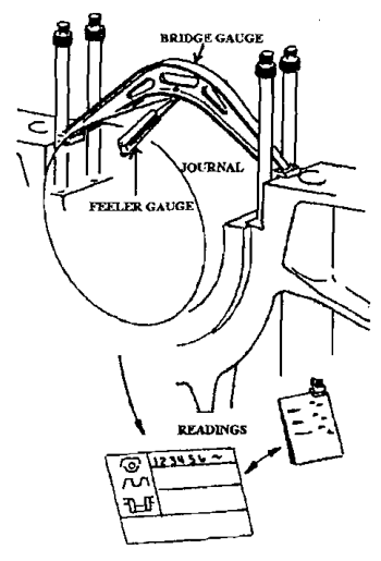
Primary Measurement Methodologies
| Method | Tools & Instrumentation | Application & Procedure |
|---|---|---|
| Bridge Gauge (Bedplate Trammel) | Engine-specific hardened steel bridge, stamped with original factory clearances; feeler gauges or depth micrometer. |
Used for Main Bearings.
Bearing Wear Calculation: Wear = Current Gauge Clearance - Stamped Baseline Clearance |
| K-Gauge / Telescopic Gauge | Calibrated dial indicator gauge rod mounted inside the bearing oil pocket without dismantling the bearing keep. | Modern two-stroke engines (MAN B&W ME series) feature access ports drilled through the bearing cap. A special K-gauge probe is inserted through the port down to the top shell back to measure journal elevation directly with the cap fully torqued. |
| Feeler Gauges | Long, flexible blade feeler gauges (0.05 mm to 1.0 mm). | Used for Crosshead and Bottom End (Crankpin) Bearings where the pin is held tightly against one shell half. Blades are inserted at the unloaded crown and side horns to measure radial running clearance and verify crown crown contact uniformity. |
| Hydraulic Jack Lift Test | Hydraulic porta-power jack fitted with pressure gauge; dial test indicator (DTI) mounted on transverse girder touching journal. | Measures total radial clearance without removing bearing keep. The journal is gently jacked upward with hydraulic pressure (limited to 50–80 bar to avoid bending shaft) until the DTI needle stops moving. The total dial needle travel equals total radial clearance. |
| Lead Wire (Plastigauge) Method | Soft lead extrusion wire (approx. 1.0–1.5 mm diameter) or calibrated polymer wax ribbon (Plastigauge). | Standard in medium-speed four-stroke trunk piston engines. Lead wires are laid across the journal crown, the bearing cap is bolted and torqued to full hydraulic pre-tension, then dismantled. The flattened wire thickness is measured with an external micrometer. |
7. Tri-Metal Bearing Tribology & Shell Failure Mechanisms
Modern large marine diesel engines utilize precision thin-wall tri-metal bearing shells engineered to withstand hydrodynamic oil wedge peak pressures exceeding 250 bar while maintaining sufficient embeddability and conformability.
Anatomy of a Tri-Metal Bearing Shell
| Layer | Material Composition | Thickness | Engineering Purpose |
|---|---|---|---|
| 1. Steel Backing Shell | Low-carbon structural steel (0.15% C) | 15 to 35 mm | Provides structural rigidity, hoop stress resistance, and precise interference fit (crush/nip) inside the bedplate bore to prevent shell spinning. |
| 2. Intermediate Lining | Lead-Bronze (CuPb70/30 or CuSn10Pb10) or Aluminum-Tin (AlSn20) | 1.0 to 2.5 mm | High fatigue strength substrate that supports dynamic combustion shock loads and provides emergency boundary running capability if the overlay is breached. |
| 3. Nickel Barrier Dam | Pure Nickel (electroplated) | 1 to 3 μm | Prevents tin from the babbitt overlay from diffusing downward into the copper substrate, which would form brittle copper-tin intermetallic compounds (Cu3Sn / Cu6Sn5) that cause overlay flaking. |
| 4. Soft Overlay (Babbitt) | Tin-Antimony-Copper or Lead-Tin-Copper (PbSn10Cu2) | 15 to 30 μm | Provides initial bedding-in conformability, absorbs hard abrasive debris particles (embeddability), and prevents journal scoring during start/stop boundary lubrication. |
Common Bearing Shell Failure Modes
- Overlay Fatigue & Craze Cracking: Cyclic hydraulic pressure pulses generate high shear stresses at the overlay-intermediate interface. Over time, a network of fine mosaic cracks ('chicken-wire' pattern) develops in the top overlay, leading to localized flaking.
- Wiping: Boundary lubrication failure caused by lube oil supply starvation, extreme local overheating (>180°C), or shaft journal mis-alignment. The soft babbitt overlay melts and smears circumferentially, choking oil grooves.
- Cavitation Erosion: Rapid micro-bubble collapse caused by high-frequency pressure oscillations in the lube oil film. Typically manifests as deep spongy pitting in the unloaded shell half near oil supply pockets.
- Fretting Corrosion on Shell Back: Occurs when bearing shell 'crush' (nip) is insufficient, allowing micro-motion between the steel shell back and the bedplate bore under alternating loads. Manifests as reddish-brown iron oxide patches and bore fretting.
8. Corrective Actions for Misalignment & Bearing Replacement Procedure
When excessive deflection or bridge gauge readings indicate that a main bearing has failed or worn past classification renewal limits, the lower bearing shell must be rolled out and replaced while preserving crankshaft geometric alignment.
Step-by-Step Main Bearing Lower Shell Roll-Out Procedure
- Safety Isolation & Preparation: Engage turning gear, post 'DO NOT START' warning tags, isolate starting air supply, close fuel valves, stop main lube oil crosshead/bearing pumps, and verify crankcase oil mist detector zeroing.
- Remove Top Keep: Connect hydraulic jacks to the main bearing keep studs. Pump to manufacturer pressure (typically 700–900 bar) to relieve nut tension, remove nuts, relieve hydraulic pressure, and hoist the upper bearing keep with shell using the engine room overhead crane.
- Mount Crankshaft Support / Relief Tool: To remove the weight of the crankshaft journal off the lower shell half, install a hydraulic jacking tool or screw-jack beneath the adjacent crank web, lifting the journal by a microscopic amount (maximum 0.03 to 0.05 mm, verified by dial indicator mounted on the transverse girder; exceeding this will bend the crankshaft).
- Install Rolling-Out Tool: Bolt the manufacturer's circular rolling-out flexible guide tool to the crank web or journal face. The tool features a driving pin that engages the parting face of the lower bearing half.
- Turn Crankshaft Slowly: Engage the turning gear in the specified direction. As the crankshaft rotates, the driving tool pushes the lower bearing shell circumferentially around the bedplate saddle bore until it emerges at the top horizontal joint.
- Inspection of Saddle & Insertion of New Shell: Inspect the bedplate bore for fretting or burrs. Thoroughly clean and oil the saddle. Insert the new pre-measured lower shell, reverse the turning gear to roll the new shell into position, ensure the locating lug locks into its recess, and verify central alignment.
- Reassemble Keep & Measure Clearances: Fit the upper shell and keep, hydraulically torque the studs to exact specification, and immediately take a new bridge gauge clearance and 5-point web deflection log to verify perfect restoration of alignment.
Practise this in the question bank
- Crankshaft / Bearing / Cylinder — 85 questions
Found a mistake, or something unclear?
Report it in a few seconds — it goes straight to the editors.
- Two-Stroke Structure — Frame, Tie Rods, Liner, Piston & Crosshead
- Marine Crankshafts — Builds, Bedplate, Chocks & Alignment
- Engine Bearings — Renewal, Crosshead to Thrust Block
- Camshaft Chain Drive, Hydraulic Tensioners & Timing Synchronisation
- Crosshead Assembly, Guide Clearances & Piston Rod Stuffing Box
- Cylinder Liner Wear, Calibration & Cold Corrosion
- Piston Crowns, Piston Rings & Thermal Mechanics
- Exhaust Valve Actuation, Air Spring Mechanics & Spindle Metallurgy
- Engine Bedplate Foundation, Holding Down Bolts & Epoxy Chocking
- Crankshaft Alignment, Web Deflections & Bearing Clearances