

Engine Bedplate Foundation, Holding Down Bolts & Epoxy Chocking
Master marine diesel bedplates: bearing saddle cracking, long holding down bolts, hydraulic tensioning, Chockfast Orange resin chocking, and side/end chocks.
Bedplate Architecture & Structural Stress Mechanics
The bedplate forms the foundational backbone of the marine diesel engine. It must provide absolute structural rigidity to support the reciprocating and rotating masses (crankshaft, connecting rods, crossheads, and running gear), maintain precise main bearing alignment within fractions of a millimeter, resist violent gas-firing and dynamic inertia forces, and transmit propeller thrust into the ship's double-bottom structure.
Structural Configurations: Deep Box-Girder vs Trestle Type
Historically, marine engine bedplates evolved through several design configurations:
- Deep Box-Girder Flat-Bottom Type (Modern Standard): Standard in modern MAN B&W (MC/ME) and WinGD (RT-flex/X-Engines) designs. The bedplate features deep longitudinal box-section girders on port and starboard sides with a completely flat bottom. This permits direct mounting onto the double-bottom engine seating (tank top) via chocks, maximizing longitudinal bending stiffness while integrating the dirty lube oil sump pan within a compact vertical envelope.
- Trestle Type (Elevated Stools): Utilized on older or smaller engines where the transverse cross-girders hung below the mounting flanges. This necessitated fabricating raised engine stools or cutting a recessed "well" into the double-bottom plating, which severely complicated shipyard steelwork and weakened double-bottom longitudinal continuity.
Material Construction: Hybrid Fabricated / Cast Steel
Because gray cast iron possesses limited tensile strength and cannot be readily repaired if fractured in heavy seaways, modern two-stroke bedplates employ a hybrid welded-and-cast construction:
- Longitudinal Girders: Fabricated from high-tensile structural mild steel plates (Grade A or B marine shipbuilding steel with good weldability, yield strength ~235–275 MPa). They are formed as continuous box girders or stiffened single/double vertical web plates. Internal vertical and horizontal stiffeners prevent web plate buckling under vertical combustion loads.
- Transverse Cross-Girders (Bearing Saddles): The transverse members house the lower main bearing shells and bear the direct downward firing thrust (up to 1,500 to 2,500 kN per cylinder). Modern practice utilizes one-piece cast steel saddles (0.2% carbon cast steel, normalized to refine grain structure). Casting allows smooth, generous transition fillets around the bearing pocket and tie-bolt bosses, eliminating sharp notch stress-raisers.
- Welded Junctions: The cast steel cross-girders are welded to the fabricated longitudinal girders using full-penetration submerged arc or flux-cored multi-pass welding with ductile, low-hydrogen electrodes matching parent metal mechanical properties.
Post-Weld Stress-Relieving Heat Treatment: during fabrication, multi-pass welding introduces severe residual tensile stresses (approaching the yield point of steel) due to thermal contraction. Once fully assembled, the entire bedplate must undergo full furnace stress-relieving annealing: heated uniformly to 580°C to 620°C, soaked at temperature for 1 hour per 25 mm of maximum plate thickness, and cooled inside the furnace at a controlled rate not exceeding 50°C/hr. Failure to stress-relieve leads to in-service distortion and spontaneous weld cracking.
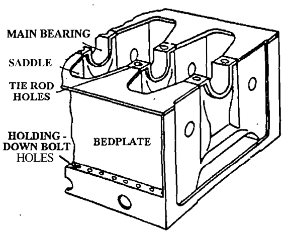
Main Bearing Saddle Failure Modes & Welded Joint Cracking
The bedplate is subjected to continuous cyclic fatigue. Every rotation of the crankshaft applies alternating vertical gas pressures, horizontal crosshead guide reactions, and torsional moments. Over millions of cycles, structural cracking can occur if operating conditions deteriorate.
Primary Locations of Bedplate Cracking
- Welds Joining Cast Steel Saddle to Longitudinal Girders: This junction experiences massive shear and bending loads as firing pressure pushes the saddle down while the ship's hull pushes upward through the foundation chocks. Inadequate weld penetration or poor pre-heating during construction causes fatigue cracks initiating at the weld root.
- Underneath the Main Bearing Pocket (Radial Cracks): High downward gas forces exert severe hoop and bending stresses across the saddle center. Cracks propagate radially downward from the bottom of the bearing bore or along the contour of the lower pocket stiffening ribs.
- In Way of Tie-Bolt and Holding-Down Bolt Holes: Tensile pre-stressing around tie-bolt counterbores can initiate radial fatigue cracks if tie-bolts loosen and allow cyclic micro-impacts.
- Around Lightening Holes: Stress concentrations around un-reinforced inspection or lightening cutouts in double-plate transverse webs.
Root Causes of In-Service Bedplate Cracking
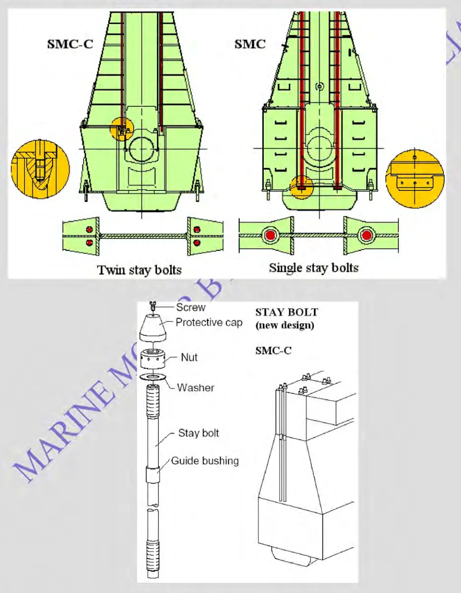
- Slack or Unevenly Tensioned Tie-Bolts: Tie-bolts maintain the entire engine structure (bedplate, A-frames, and cylinder block) in perpetual compression. If a tie-bolt slacks off, firing pressure subjects the bedplate cross-girder to extreme cyclical tensile bending moments that rip the cast steel saddle.
- Slack Holding-Down Bolts & Loose Chocks: When foundation chocks fret or bolts loosen, the bedplate loses its continuous flat support. The bedplate flexes under every combustion stroke, transmitting massive fatigue stresses to the saddle welds.
- Excessive Bearing Wear and Journal Misalignment: If a main bearing shell wears down abnormally, adjacent bearings take an unequal share of crankshaft loading. This causes journal bending and cyclic localized hammering against the saddle pocket.
- Hull Deflection in Heavy Weather: Violent wave action causes severe hull hogging, sagging, and torsion, which is transferred into the bedplate if chocking is degraded.
Class-Approved Crack Repair Procedures
If cracking is detected during crankcase visual inspection or routine drydock surveys:
- Non-Destructive Evaluation: Clean area to bare metal. Conduct Magnetic Particle Inspection (MPI) or Dye Penetrant Testing (DPT) to trace the exact crack path, branches, and depth. Ultrasonic testing (UT) determines through-thickness penetration.
- Crack Arrest Holes: Drill a 6 mm to 10 mm hole at the extreme tips of the crack. This eliminates the infinite stress concentration factor (Kt) at the razor-sharp crack tip, preventing further propagation while preparations are made.
- Gouging & Edge Preparation: Use mechanical chipping, grinding, or carbon-arc gouging to grind out the crack completely into a U- or double-V groove down to sound metal. Re-test with DPT to confirm 100% defect removal.
- Welding with Low-Hydrogen Electrodes:
- Preheat the surrounding casting and girder plates to 150°C to 200°C using induction heating or propane torches to avoid hydrogen-induced cold cracking.
- Weld using ductile, low-hydrogen basic electrodes (e.g., AWS E7018 or high-nickel Ni-Fe alloys for ductile iron). Deposit multi-pass stringer beads with light peening between passes to relieve shrinkage stress.
- Maintain controlled post-weld cool-down wrapped in ceramic insulating blankets. Grind flush and re-test with MPI.
- Metalock Stitching (for Cast Iron): For gray iron bedplates where fusion welding causes hard, brittle martensite phases, mechanical cold repair using high-nickel alloy "Metalock" keys inserted across the fractured joint is the only Class-approved method.
Holding Down Bolts: Physics, Elasticity & Hydraulic Tensioning
A common misconception among junior engineers is that holding down bolts act as dowels to resist engine shear forces. Holding down bolts must NEVER be subjected to shear!
The Physics of Frictional Clamping
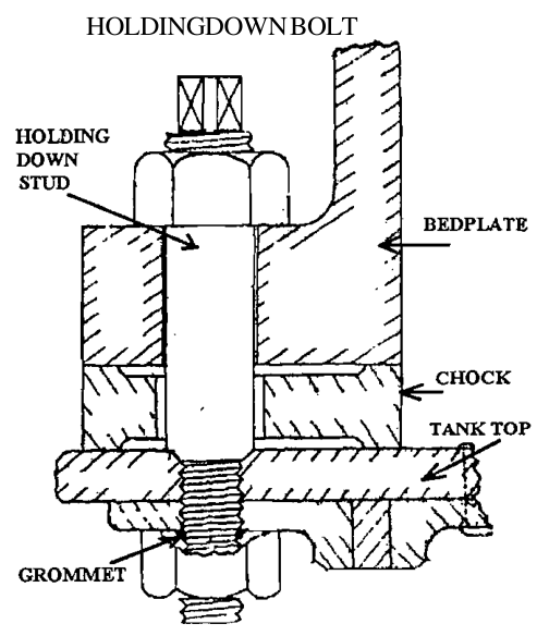
The sole mechanical purpose of holding down bolts is to apply immense, permanent downward tensile clamping force, squeezing the bedplate, chocks, and ship's tank top together. It is the frictional grip generated across these interfaces that transfers propeller thrust, transverse guide reaction forces, and ship dynamic moments into the hull:
Bedplate Frictional Grip Transmission Equation
Ffriction, max = μ · ∑ Fclamping = μ · (Nbolts · Fpretension + Wengine)
Where μ = coefficient of friction (≈ 0.15–0.20 for oiled steel/epoxy), Nbolts = total number of holding down bolts (typically 60 to 120 on a large engine), Fpretension = hydraulic bolt preload, and Wengine = static weight of the engine.
If holding down bolts loosen, the clamping pressure drops below the threshold required to maintain frictional grip. The bedplate begins to slide microscopically against the chocks under dynamic crosshead guide forces. This relative movement causes rapid fretting corrosion, grinding away metal, loosening adjacent bolts, and ultimately bending the bolts in shear until catastrophic fatigue fracture occurs.
Why Long Elastic Bolts Are Used (The Physics of Stored Strain)
Modern engines exclusively utilize long holding down bolts (extending through a cast spacer distance pipe or passing through the entire double bottom top stool) rather than short studs threaded directly into the top plate. This is governed by two fundamental physical principles:
- 1. Resistance to Slackening via Stored Elastic Strain:
Hooke's Law dictates that axial elongation is directly proportional to bolt length (L):
ΔL = F · L A · E
A long bolt (e.g., L = 800 mm) stretches by 1.5 to 2.5 mm when tensioned to its working pre-load, whereas a short stud (L = 100 mm) stretches by only 0.2 mm. When the ship encounters heavy waves, hull flexing causes microscopic settling and thickness variations (0.05 mm) in the foundation. In a short bolt, a 0.05 mm loss of thickness destroys 25% of its pre-load! In a long bolt, a 0.05 mm deflection represents less than 2% of the stored elongation, guaranteeing continuous, uninterrupted clamping tension throughout extreme hull distortion.
- 2. Drastic Reduction in Bending Fatigue Stress:
As the ship's double-bottom structure flexes under hogging and sagging, relative transverse and longitudinal displacement occurs between the rigid bedplate and the flexible tank top. When a bolt is forced to bend through a lateral displacement (δ), the resulting bending stress (σb) is inversely proportional to the square of its length:
σb = 3 · E · d · δ 2 · L2
By increasing bolt length L, the radius of curvature during hull flexing becomes significantly larger, slashing cyclic bending stresses below the endurance fatigue limit of the steel alloy.
Spherical Washers
Even with long bolts, foundation plating cannot be guaranteed to be perfectly parallel to the bedplate flange. To prevent high localized bending stresses under the nut head, spherical washers (convex-to-concave spherical seating sets) are fitted under the tightening nuts. The spherical radius allows the nut to self-align perpendicularly to the bolt axis, ensuring 100% pure axial tension without eccentric bending moments.
Hydraulic Tensioning Procedure
Holding down bolts are tightened exclusively using hydraulic bolt tensioners:
- The hydraulic jack is screwed onto the extended puller threads of the holding down bolt above the hexagon nut.
- High-pressure hydraulic oil from a pneumatic-driven pump is admitted to the jack, pressurizing the annular cylinder to 800 to 900 bar (calibrated to the manufacturer's exact pre-load tonnage).
- The hydraulic piston expands, stretching the bolt elastically purely in the axial direction. No torque is applied to the bolt shank, totally eliminating torsional shear stresses.
- While under full hydraulic pressure, the engine nut is rotated down flush against the spherical washer using a light tommy bar until firm metal-to-metal seating is achieved.
- Hydraulic pressure is vented, transferring the elastic stretch from the jack directly into the clamped assembly.
Chocking Technology: Cast Iron vs Pourable Epoxy Resin (Chockfast)
Between the machined underside of the bedplate and the ship's tank top plating, chocks must be interposed. A marine diesel engine can never be mounted directly onto ship plating because shipbuilding tolerances result in surface waviness, plate angularity, and structural deflection that would twist the bedplate and snap the crankshaft within hours.
1. Traditional Hand-Fitted Metal Chocks (Cast Iron / Mild Steel)
For over a century, engines were mounted on cast iron or mild steel chocks:
- Fabrication & Taper: Chocks are machined with an upper flat face and a bottom face tapered at 1:100 to match corresponding welded foundation pads on the tank top.
- Hand Fitting & Scraping: Shipwrights hand-scrape each individual chock using Prussian blue marking paint. The chock is repeatedly hammered in, withdrawn, checked for contact spots, and filed or scraped by hand until an absolute minimum of 80% to 85% uniform contact area is achieved across the entire face, verified with a 0.05 mm feeler gauge.
- Severe Operational Drawbacks:
- Extreme labor cost: Fitting 80 to 120 chocks by hand on a 7-cylinder container engine required 3 to 5 weeks of continuous, skilled shipyard labor.
- Vulnerability to fretting: Even with 85% contact, microscopic air voids exist. Any slackening of holding down bolts allows oil and bilge water to enter, causing catastrophic fretting corrosion that eats the metal chocks away.
2. Modern Pourable Epoxy Resin Chocks (Chockfast Orange)
Today, over 95% of all newbuilding commercial vessels and engine retrofits utilize pourable polymer resin chocking systems, with Chockfast Orange being the premier class-approved standard.
Technical Characteristics of Chockfast Orange
| Property | Technical Value / Specification | Engineering Significance |
|---|---|---|
| Ultimate Compressive Strength | 131 MPa (19,000 psi) at 23°C | Over 4 times higher than maximum permissible engine loading; zero crushing under peak firing impulses. |
| Compressive Modulus of Elasticity | 3,675 MPa (533,000 psi) | Slightly flexible compared to steel, providing superior vibration attenuation and damping transmission noise. |
| Linear Shrinkage During Cure | Negligible (< 0.001 mm/mm) | Ensures intimate surface replication without pulling away from the bedplate. |
| Max Operating Temperature | 80°C continuous (approved by all IACS classes) | Easily withstands hot crankcase lube oil drain temperatures (typically 50°C to 65°C). |
| Max Design Surface Loading | Static: 3.5 MPa / Total (Static + Dynamic): 5.0 MPa | Mandatory classification design ceiling ensuring zero creep or permanent deformation over ship lifetime. |
Step-by-Step Epoxy Resin Pouring Procedure
- Alignment on Jacking Screws: The engine bedplate is aligned to the propeller shaft driving flange using jacking screws. Clearance between the bedplate and tank top is adjusted to the designed chock thickness (nominal 25 mm to 45 mm).
- Surface Preparation & Cleaning: Mill scale, rust, paint, and oil are removed using wire brushes or grit blasting. Mating surfaces are degreased with approved solvent (trichloroethane or residue-free solvent).
- Bolt Preparation & Sleeve Isolation: Holding down bolts are inserted into their holes. To prevent the epoxy resin from adhering to the bolts, bolts are tightly wrapped in non-absorbent closed-cell foam tubing or coated with a specialized liquid wax release agent.
- Damming: Open-cell foam strips, aluminum plates, and sealing mastic/putty are installed around each chock perimeter. The front dam is fabricated with an angled metal lip extending 15 to 25 mm above the bedplate bottom flange to form an "overfill pouring head" (riser). This head ensures hydrostatic pressure to force out air bubbles and accommodates any micro-shrinkage in the riser instead of the load-bearing chock body.
- Mixing & Pouring: Epoxy resin and hardener are stored between 20°C and 25°C prior to mixing. The hardener is blended into the resin can using a low-speed mechanical mixer (200–250 RPM) for exactly 3 to 4 minutes to avoid air bubble entrainment. The mixture is poured continuously into one side of the damming box, allowing the liquid resin to displace air ahead of it until the overfill riser is completely filled.
- Curing Time vs Ambient Temperature:
- At 25°C: full cure in 24 to 36 hours.
- At 15°C: cure requires 48 to 60 hours.
- Never pour below 13°C without supplemental radiant space heaters!
- Finishing & Tensioning: After curing and hardness verification (Barcol hardness tester > 35 or Shore D > 85), the overfill riser is chipped away. Jacking screws are backed out completely, and holding down bolts are hydraulically tensioned to full service pre-load.
Side Chocks, End Thrust Chocks & Thermal Expansion Dynamics
Holding down bolts and support chocks carry vertical weights and resist overturning moments. However, substantial lateral and axial forces require dedicated structural locking: side chocks and end chocks.
1. Transverse Side Chocks
During engine operation, the crosshead slippers exert violent, alternating horizontal reaction forces against the engine A-frame guide bars (several hundred kilonewtons switching from port to starboard every half-revolution). Furthermore, violent ship rolling in heavy seas exerts massive lateral inertia loads:
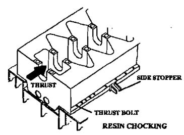
- Arrangement: Side chocks are heavy cast or fabricated steel brackets welded securely to the ship's double-bottom foundation plate directly in way of each transverse cross-girder.
- Tapered Liners: A hardened steel liner machined with a 1:100 taper is hand-fitted between the side chock bracket and the bedplate side face. Both mating faces must achieve an 80% contact area.
- Installation: Liners are driven in tightly using a heavy sledgehammer, advancing 3 to 4 mm beyond hand-tight position, and secured in place by locking pinch screws (grub screws) that prevent back-out. Side chocks are installed in matching opposing pairs across port and starboard to preserve lateral alignment.
2. Longitudinal End / Thrust Chocks
The propeller thrust is transferred from the thrust shaft through the thrust pads and thrust block casing directly into the aft end of the engine bedplate:
- Aft End Chocks: Massive end chocks are welded to the foundation plating at the AFT end of the bedplate only. Precision-machined 1:100 tapered wedges are driven between these chocks and the aft bedplate flange to directly transmit propeller forward push into the ship's keel structure.
- Collision Chocks: Fitted on the forward face of the aft cross-girder to prevent the engine from leaping forward during a head-on vessel collision or heavy grounding.
The Absolute Rule of Forward Thermal Expansion
Warning — Why Are There NO End Chocks at the Forward End? Under NO circumstances may fixed end chocks ever be fitted at the forward end of a marine diesel engine!
When a large two-stroke engine runs at full sea speed, lube oil and cooling water warm the entire steel structure from cold ambient (20°C) to operating temperature (60°C to 70°C). Over an engine length of 15 to 25 meters, the bedplate expands longitudinally by several millimeters:
Bedplate Thermal Expansion Equation
ΔL = α · L0 · ΔT
Where α = coefficient of linear thermal expansion for steel (≈ 12 × 10−6 / °C), L0 = total bedplate length (e.g., 20 m = 20,000 mm), and ΔT = temperature rise (65°C − 20°C = 45°C).
ΔL = 12 × 10−6 × 20,000 mm × 45°C ≈ 10.8 mm!
If rigid end chocks were fitted at both the forward and aft ends, this 10.8 mm of thermal expansion would be completely constrained. The resulting compressive thermal force would exceed tens of thousands of kilonewtons, causing catastrophic buckling of the bedplate, misalignment of the crankshaft journals, bearing seizure, and structural cracking!
Therefore, the engine is permanently anchored at the aft end (thrust block datum), allowing the entire forward length of the bedplate to expand freely forward. Forward side chock liners and foundation bolt holes are machined with longitudinal sliding clearances to accommodate this movement without restraint.
Watchkeeping, Inspection Protocols & Web Deflection Correlation
Bedplate integrity and holding down bolt security must be systematically verified throughout the vessel's operational life. Undetected loosening leads directly to crankshaft misalignment and catastrophic shaft fracture.
Class Survey and Maintenance Intervals
Classification societies (IACS) mandate strict holding down bolt re-tightening checks on new vessels or rechocked installations:
- First Maiden Voyage Check: At 500 running hours.
- Intermediate Running Checks: At 1,000 hours, 2,000 hours, and 4,000 hours.
- Routine In-Service Protocol: Every 8,000 running hours or annually.
- Class Special Survey: 100% check by a Classification Surveyor every 5 years.
The Tactile "Hammer Sounding" Test
A traditional yet highly reliable non-destructive test utilized by marine chief engineers:
- The engineer uses a 0.5 kg ball-peen hammer.
- Place the thumb and forefinger firmly across the split line between the bottom face of the hexagon nut and the spherical washer/flange surface.
- Strike the opposite hexagonal flank of the nut sharply with the hammer.
- Tight Bolt: Emits a clear, crisp, metallic ringing sound. No physical relative movement is detected by the thumb.
- Loose / Slack Bolt: Emits a dull, hollow, thudding sound. The nut and stud momentarily "spring" laterally against the engineer's thumb. Any palpable movement indicates immediate loss of pre-load.
- Note for Fitted Bolts: Fitted bolts (dowels) cannot be reliably tested by hammer sounding because the tight hole interference masks slackness; hydraulic pullers must be connected to verify lift pressure.
Feeler Gauge Chock Perimeter Inspection
Inspect all support chocks (metal or epoxy) around their accessible perimeters using a 0.05 mm feeler gauge. The feeler gauge must not penetrate between the bedplate and chock or between the chock and tank top. Any entry exceeding 5 to 10 mm depth indicates localized fretting, chock crushing, or foundation plate distortion that requires immediate re-chocking.
Correlation with Crankshaft Web Deflections
Whenever loose holding down bolts or damaged chocks are detected, the Chief Engineer must immediately take and record a complete set of cold and hot crankshaft web deflections:
- If holding down bolts slacken under a specific cylinder, the bedplate sags locally into the gap. This pulls the main bearing journals downward, inducing massive positive or negative vertical web deflections (Δ = Bottom − Top) across adjacent crank webs.
- Re-tightening a loose bolt without verifying chock seating will clamp the bedplate into a warped contour, permanently distorting the crankshaft axis and causing cyclic reverse-bending fatigue that will snap the crankshaft journal within months.
Summary Troubleshooting Matrix
| Observed Fault | Probable Root Causes | Corrective Action |
|---|---|---|
| Reddish-brown powder ("cocoa") around chock edges | Severe fretting corrosion caused by loose holding down bolts; metal-to-metal rubbing in presence of oil/moisture. | Slack bolts immediately. Check chock contact with 0.05 mm feeler. If fretted, remove metal chock, grind foundation flat, and pour replacement epoxy chock. |
| Excessive crankshaft web deflection on single unit | Crushed chock, slack holding down bolts, or cracked bedplate cross-girder under that cylinder. | Perform thorough crankcase NDT inspection. Check bolt tightness with hydraulic jack. Re-level engine if chocks have settled. |
| Epoxy chock cracking or crumbling |
|
Chisel out defective epoxy chock completely. Re-align engine unit, install proper damming with overfill riser, and re-pour with certified Chockfast Orange. |
| Cracking in welds between saddle and side girder |
|
Drill 8 mm crack arrest holes at ends. Carbon-arc gouge to sound metal, preheat to 180°C, and weld with ductile low-hydrogen electrodes under Class supervision. |
Found a mistake, or something unclear?
Report it in a few seconds — it goes straight to the editors.
- Two-Stroke Structure — Frame, Tie Rods, Liner, Piston & Crosshead
- Marine Crankshafts — Builds, Bedplate, Chocks & Alignment
- Engine Bearings — Renewal, Crosshead to Thrust Block
- Camshaft Chain Drive, Hydraulic Tensioners & Timing Synchronisation
- Crosshead Assembly, Guide Clearances & Piston Rod Stuffing Box
- Cylinder Liner Wear, Calibration & Cold Corrosion
- Piston Crowns, Piston Rings & Thermal Mechanics
- Exhaust Valve Actuation, Air Spring Mechanics & Spindle Metallurgy
- Engine Bedplate Foundation, Holding Down Bolts & Epoxy Chocking
- Crankshaft Alignment, Web Deflections & Bearing Clearances