

Fuel Oil System — Interactive One-Line Diagram
Full fuel oil system P&ID: bunkering, storage, transfer, settling, purifier loop, service tank, supply and circulating pumps to the main engine.
1. Interactive P&ID Line Diagram
The complete marine fuel oil transfer, conditioning, and engine circulating system standardized into modern P&ID symbology. Hover over any symbol to inspect its specifications, and use mouse wheel or toolbar buttons to zoom and pan across the full vessel layout.
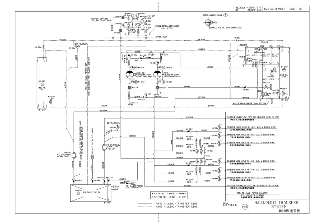
Reference: Ship's Piping Diagram
Below is the shipyard drawing of the fuel oil transfer and bunkering arrangement. The value of reading it next to the interactive diagram is that it shows the whole bunker-to-service trail as one continuous line: bunker tanks, transfer pumps, the settling and service tanks, and the heater and purifier connections that condition the oil before it reaches the engine. Note how much of the drawing is valves and cross-connections — transfer systems are designed for routing flexibility more than for simplicity.
2. End-to-End System Flow: From Bunker Hose to Engine Rail
Marine heavy fuel oil (HFO/VLSFO) cannot be fed directly from bunker tanks into marine diesel engines. It contains catalyst fines (Al+Si), moisture, abrasive ash, and asphaltenes, and exhibits extremely high viscosity at ambient temperatures. The fuel must traverse six distinct thermodynamic and physical separation stages before entering the fuel injection pumps:
Stage 1: Bunkering & Storage (40–50 °C)
Fuel enters via the port or starboard bunker manifold through full-bore gate valves and passes a continuous drip sampler. It gravity-fills double bottom or deep storage tanks equipped with steam heating coils. Oil is held at 40–50 °C (strictly minimum 20 °C below the closed flash point) to ensure pumpability without excessive vapor evolution.
Stage 2: Transfer to Settling Tank (50–70 °C)
A positive-displacement screw transfer pump draws fuel through suction strainers and discharges it into the HFO Settling Tank. Maintained at 50–70 °C, gravity stratification allows heavy sludge, sediment, and free water to drop to the bottom cone where it is drained daily via self-closing cocks.
Stage 3: Centrifugal Purification Loop (95–99 °C)
The purifier feed pump draws from the high suction of the settling tank, pumps oil through a steam pre-heater to reach 95–99 °C, and feeds the disc-stack centrifuge. Water and catalyst fines are discharged to the sludge tank, while purified fuel returns via a sight glass into the HFO Service Day Tank.
Stage 4: Service Day Tank & De-Aeration
The Service Tank holds conditioned fuel ready for consumption (minimum 8 hours full power consumption per SOLAS). It is fitted with heating coils (75–85 °C), a remote-operated quick-closing valve (QCV) on the outlet, high/low level alarms, and an overflow line to the overflow tank.
Stage 5: Supply (Booster) Circuit (4–5 bar)
Two supply pumps (1 duty, 1 standby) draw from the service tank through fine suction strainers and boost pressure to 4–5 bar. This positive pressure prevents hot volatile light fractions from boiling and gassing off as fuel enters the high-temperature circulating loop.
Stage 6: Circulating Circuit & Injection (118–130 °C, 7–9 bar)
Circulating pumps boost fuel to 7–9 bar through final steam heaters reaching 118–130 °C. An automatic viscosity controller (Viscotherm) modulates heating steam to maintain exactly 10–14 cSt. Oil passes 25 µm duplex auto-backflush filters into the engine fuel rail. Unburned excess fuel loops through the buffer/venting bottle back to pump suction.
Operating parameters summary: Storage at 40–50 °C · Settling at 50–70 °C · Purification at 95–99 °C · Service Tank at 75–85 °C · Engine Rail at 118–130 °C maintaining 10–14 cSt at 7–9 bar.
3. Critical Components: Working Principles & Design Specs
| Component | Type / Standard | Working Principle & Internal Operation | Safety & Regulatory Function |
|---|---|---|---|
| Quick-Closing Valves (QCV) | Hydraulic, pneumatic, or weighted wire-pull trip valve | Normally held open against a heavy internal helical spring by a latch or piston cylinder. Upon releasing the latch or venting pressure, the spring slams the disc down onto the seat in <1 second. | SOLAS II-2/4.2.2.3.4: Mandatory on all settling, service, and storage tank outlets >500 L. Remotely tripped from the Fire Control Station / Bridge in case of engine room fire. |
| Fuel Oil Transfer Pump | Positive-displacement screw / lobe pump | Intermeshing helical screws rotate inside a close-tolerance casing, trapping pockets of oil axially and advancing them from suction to discharge at constant volumetric displacement regardless of back-pressure. | Integral Relief Bypass: Because positive displacement pumps develop high hydrostatic pressures if discharged against a shut valve, an adjustable spring relief valve bypasses oil back to suction. Emergency stops located outside the E/R. |
| HFO Settling Tank | Gravity separation tank with bottom sump cone | Operates on Stokes' Law: water droplets and abrasive sediment have higher density than heated oil. Heated to 50–70 °C to reduce oil viscosity, accelerating particle descent. | Fitted with high and low suction valves (low suction used only during emergency), high-level acoustic alarm, and self-closing spring drain cocks to prevent accidental flooding. |
| Purifier Feed Heater & Centrifuge | Disc-stack high-speed centrifugal separator | Bowl rotates at 6,000–8,000 RPM generating up to 10,000 g. Conical discs divide the oil stream into 0.5 mm laminations. Water forms an outer ring; clean oil discharges inward over the gravity disc/paring disc. | Purifier loop must maintain 95–99 °C to maximize density differential between water and oil. Discharges catalyst fines (Al+Si) which destroy cylinder liners if unremoved. |
| Buffer / Venting Column | Vertical de-aerating mixing vessel | Receives hot unburned fuel returning from the engine rail (120–135 °C). Internal baffle allows entrained air, steam, and light hydrocarbon bubbles to vent upward to the service tank goose-neck. | Prevents vapor lock and cavitation in circulating pump suctions. Maintains a constant positive suction head and dampens pressure pulsations caused by fuel injection pump displacement shocks. |
| Viscotherm / Viscosity Regulator | Capillary differential pressure sensor | A dedicated synchronous motor and precision gear pump draws a constant flow through a calibrated capillary tube in laminar regime (Reynolds number < 2000). By Hagen-Poiseuille law, the pressure drop is directly proportional to dynamic viscosity. | A differential pressure transmitter outputs a 4–20 mA signal to a pneumatic diaphragm control valve, modulating heating steam to maintain exact injection viscosity (10–14 cSt). |
| Supply & Circulating Pumps | Centrifugal or twin-screw (2 × 100% capacity each) | Supply pumps maintain 4–5 bar from service tank to buffer column. Circulating pumps pressurize oil to 7–9 bar through final heaters to fuel pumps. Flow rate is 3–4× engine consumption to cool injectors. | Parallel duplicate arrangement ensures zero interruption: if the duty pump trips, the standby pump auto-starts via pressure sensor relay. |
| Duplex Auto-Backflush Filter | Multi-candle wire mesh filter (25–34 µm) | Fuel flows outside-in through fine mesh candle elements. When differential pressure reaches ~0.5–0.8 bar, an air-driven motor rotates a backwash arm to reverse-flush each pod sequentially. | Protects precision fuel pump plungers and injector needle seats from abrasive wear. Backflushed sludge drains to the dirty oil drain tank for reclamation. |
4. Viscosity Control: Hagen-Poiseuille Principle
Attempting to control fuel combustion by temperature alone is unreliable because different bunker batches have widely varying viscosity indices. Heavy residual fuels with identical viscosity at 50 °C may require 118 °C or 138 °C to reach the required injection viscosity. An automated viscometer (such as the VAF Viscotherm) is therefore standard on marine installations.
The Viscotherm incorporates a small motorized gear pump driving a constant volumetric flow Q through a calibrated capillary tube of length L and internal bore diameter D under laminar flow conditions:
Because length L, flow rate Q, and diameter D are fixed physical parameters of the sensor, the measured pressure drop (ΔP) changes exclusively with dynamic viscosity (μ). Differential pressure taps send a signal to a controller that modulates the steam supply valve on the fuel heaters, automatically maintaining the 10–14 cSt setpoint.
5. Regulatory Requirements (SOLAS & Class)
SOLAS Closed Flash Point Limit (≥ 60 °C)
Under SOLAS Reg II-2/4.2.1, no fuel oil with a closed-cup flash point below 60 °C (determined by Pensky-Martens apparatus) may be used for marine machinery, except for emergency generators (min 43 °C). Fuel in storage must never be heated within 20 °C of its flash point, and must not exceed 51 °C in unvented bunker tanks.
Tank Air Pipes & Flame Screens (125% Area)
Air pipes leading from oil fuel tanks must have a total cross-sectional area at least 25% greater (1.25×) than the filling line to prevent structural over-pressurization during bunkering. Outlets terminate in goosenecks on the open weather deck fitted with detachable stainless steel flame screens (wire gauze mesh).
Fuel Changeover Thermal Shock Limit (≤ 2 °C/min)
During fuel changeovers (such as switching to low-sulfur MGO when entering an Emission Control Area), the rate of fuel temperature change at the engine inlet must never exceed 2 °C per minute. Exceeding this rate induces rapid thermal contraction of fuel pump barrels around hot plungers, causing pump seizure.
Self-Closing Drain Cocks
Drain valves fitted to settling and service tanks for bottom water and sludge removal must be of the spring-loaded, self-closing type with counterweighted levers. They require constant manual holding to remain open; releasing the handle immediately shuts the drain.
6. High-Frequency Oral Exam Questions
-
Why are there two sets of pumps (Supply Pumps and Circulating Pumps) in modern marine fuel systems?
Supply (booster) pumps draw fuel from the service tank and maintain a pressurized feed of 4–5 bar to the mixing column. This positive pressure prevents hot return fuel (at 120–130 °C) from flashing into gas or boiling under atmospheric suction. The circulating pumps then take this de-aerated, pressurized fuel and circulate it around the engine fuel rail at 7–9 bar, delivering 3 to 4 times the actual engine fuel consumption rate to keep injectors cool and purged.
-
What is the purpose of the Buffer / Venting column located between the engine return and circulating pump suction?
Hot excess fuel returned from the engine injectors contains entrained air, vaporized light fractions, and pressure shock waves generated by unit pump spill valves. The vertical buffer column dampens these hydraulic pulsations, provides a calming zone for vapor to separate and vent to the day tank, and ensures a solid, bubble-free liquid head to the circulating pump suctions, eliminating pump cavitation.
-
How would you test a Quick-Closing Valve without risking a main engine blackout?
Never trip the in-use service tank QCV while the main engine is operating on heavy fuel. Before testing: (1) Switch the engine fuel supply to the standby service tank or diesel oil line; (2) Close the manual isolation valve upstream of the QCV on the tank under test; (3) Verify the local release cylinder/wire linkage operates smoothly and the valve stem drops fully; (4) Reset the valve by winding down the screw handle to engage the latch and winding it back up to the open position; (5) Confirm the pneumatic/hydraulic pressure is recharged or pull wire is re-tensioned.
-
Why does a positive displacement transfer pump require an internal spring relief valve while a centrifugal pump does not?
Centrifugal pumps generate flow dynamically through kinetic energy; if their discharge valve is closed, the impeller simply slips in the liquid and pressure reaches a finite "shut-off head." A positive-displacement pump (screw or gear) mechanically moves a fixed volume of fluid per revolution. If the discharge valve is closed, pressure rises rapidly until mechanical destruction (pipe rupture, casing burst, or motor overload) occurs. The integral relief valve provides an immediate fail-safe bypass back to the suction chamber.
Standards & sources referenced
- SOLAS: International standards for the safety of life at sea.
- Conventions index
Practise this in the question bank
- Fuel Oil System — 40 questions
Found a mistake, or something unclear?
Report it in a few seconds — it goes straight to the editors.
- Fuel Oil System — Interactive One-Line Diagram
- Marine Compressed Air & Main Engine Starting Air System
- Marine Central Cooling Water System (HT / LT / SW)
- Lubricating Oil System — Interactive One-Line Diagram
- Bilge, Ballast & Fire Main System — Interactive One-Line Diagram
- Steering Gear — Interactive One-Line Diagram
- Steam and Condensate System — Interactive One-Line Diagram