

Scavenge Fires, Trunk Safety & Relief Devices
Master marine engine scavenge fires: combustion mechanics, blow-by, drain piping, CO2/steam smothering systems, relief valves, and MEO emergency procedures.
1. Thermodynamics & Chemical Mechanisms of Scavenge Air Fires
In crosshead two-stroke marine diesel engines, the scavenge air receiver and under-piston trunk spaces provide a continuous reservoir of pressurized, oxygen-rich air (typically 1.5 to 3.5 bar gauge depending on engine load) required for cylinder scavenging and combustion. However, this same space can transform into an enclosed furnace when the three components of the classical fire triangle converge: accumulated combustible hydrocarbons (fuel), a continuous oxygen supply from the turbocharger, and a high-temperature ignition source.
Understanding the exact mechanisms behind deposit formation and subsequent thermal ignition is critical for both the prevention and containment of scavenge fires:
| Combustible Element | Source of Ingress | Chemical / Physical Characteristic |
|---|---|---|
| Cylinder Lubricating Oil | Excessive cylinder oil feed rate, malfunctioning electronic lubricator (Pulse / Alpha quills leaking), or incorrect feed distribution profile. | High auto-ignition temperature (approx. 330°C to 380°C) when clean; lowers dramatically (down to 250°C–280°C) when degraded into cracked light ends and carbonaceous sludge. |
| Unburnt Residual Fuel (HFO / VLSFO) | Faulty fuel injector (dripping nozzle, low needle opening pressure, eroded spray holes, delayed atomization), improper fuel heating viscosity, or poor combustion timing. | Heavy aromatics, asphaltenes, and unburnt fractions wash down past the liner walls into the scavenge ports and deposit on receiver bottom plates. |
| Crankcase System Oil Contamination | Worn, broken, or improperly installed piston rod stuffing box scraper rings; damaged stuffing box garter springs allowing crankcase splash oil to be pumped upwards into the under-piston space. | System oil (SAE 30/40, un-additized with base reserve) accumulates in the bottom of the scavenge space, forming an emulsified oil layer with drain sludge. |
| Carbon Soot & Combustion Ash | Combustion chamber blow-by past worn, stuck, or broken piston rings; collapsed ring packs; scuffed liner surfaces with micro-seizures. | Spongy, highly porous matrix of amorphous carbon that adsorbs fuel and lube oil fractions, providing an expansive surface area for rapid oxidation. |
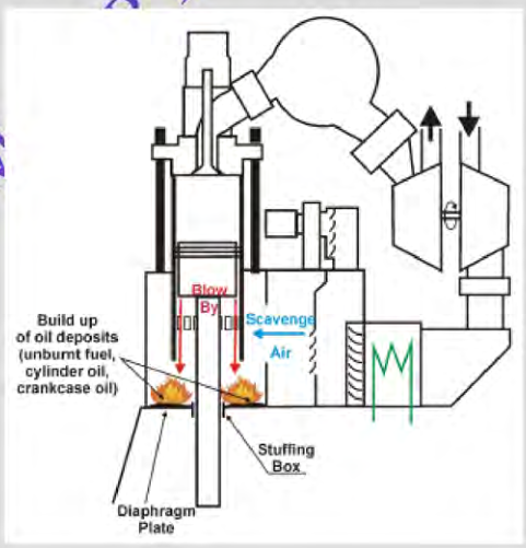
The Two Classifications of Scavenge Fires
Marine engine scavenge fires are categorized into two distinct operational severity classes based on deposit maturity and thermal intensity:
- Category 1: Low-Intensity Carbon / Sludge Fire (Small Soot Fire): Involves the surface smoldering and burning of soft carbon deposits, excess cylinder oil, and sludge on the scavenge space floor plates. The fire is relatively localized, temperatures generally stay below 400°C, and it can frequently be controlled by cutting fuel to the affected unit, lowering engine load, and allowing the accumulated deposits to burn off while monitoring the scavenge trunk closely.
- Category 2: High-Intensity Metallic / Iron Fire (Fierce High-Temperature Fire): If a Category 1 fire is starved of cooling or allowed to escalate under high oxygen flow, temperatures can exceed 700°C to 1000°C. At these extreme temperatures, the dry carbon and cylinder oil ignite with fierce blowpipe intensity. Worse, when temperatures exceed 1000°C–1100°C, an iron fire (self-sustaining oxidation of cast iron and steel components) can occur, causing irreversible thermal distortion of the cylinder liner, piston skirt, crosshead guides, and scavenge receiver walls, risking complete engine seizure.
2. Operational Indications & Diagnostic Signatures
Early detection of a scavenge fire is paramount to prevent transition from a localized sludge burn to a devastating high-intensity metal fire. Modern electronic two-stroke engines (MAN B&W ME-C / WinGD X-DF) incorporate continuous scavenge space temperature monitoring at multiple points per cylinder, but watchkeeping engineers must synthesize multiple diagnostic signatures:
| Diagnostic Parameter | Instrument / Observation | Physical Phenomenon & Cause |
|---|---|---|
| Scavenge Trunk Temperature | PT100 resistance temperature detectors (RTDs) in each under-piston space; scavenge air trunk alarm set at 60°C–80°C. | Rapid, localized temperature spike in the affected cylinder's under-piston receiver space as radiant and convective heat from the fire warms the intake charge. |
| Exhaust Gas Temperature | Cylinder exhaust thermocouple downstream of exhaust valve. | Initially rises due to delayed combustion or blow-by; subsequently drops or fluctuates erratically as scavenge air charge density decreases and combustion efficiency collapses. |
| Turbocharger Surging | Loud rhythmic gasping/thumping from the turbocharger compressor intake; erratic boost pressure gauge. | Thermal expansion in the scavenge space raises back-pressure against the compressor delivery diffuser, shifting the compressor operating point past its surge line into aerodynamic stalling. |
| Engine Speed (RPM) Reduction | Digital tachometer / Bridge RPM readout. | Loss of power in the affected cylinder due to depleted oxygen, high thermal resistance, and increased piston ring friction; governor attempts to compensate by increasing fuel index on remaining cylinders. |
| Visual & Acoustic Indications | Scavenge box sight glasses, exterior receiver paint blistering, drain pipe discharge cocks, scavenge relief valve spitting. | Paint on scavenge inspection doors discolors and blisters (turns white or peels); dense black smoke or burning sparks emit from open scavenge drain sampling cocks; dull thuds or chattering from scavenge relief valves. |
Thermodynamic Heat Release in Scavenge Receiver Fire
Qgen = ṁoil × LHVoil + ṁfuel × LHVfuel × ηcomb
Where Qgen is the rate of heat release into the scavenge trunk (kW), ṁ is the mass consumption rate of oil/fuel deposits (kg/s), and LHV is the lower heating value (approx. 42,700 kJ/kg for fuel, 41,500 kJ/kg for cylinder oil). In a high-intensity fire, Qgen far exceeds the heat dissipation capacity of the scavenge trunk cooling jacket, causing exponential air temperature elevation.
3. Scavenge Air Box Drain Architecture & Maintenance
The scavenge air box drain system is the primary defense line against scavenge fires. Its sole engineering objective is to continuously evacuate unburnt cylinder oil, fuel leakage, carbon particulate, and condensed water out of the under-piston spaces before they can form combustible pools.
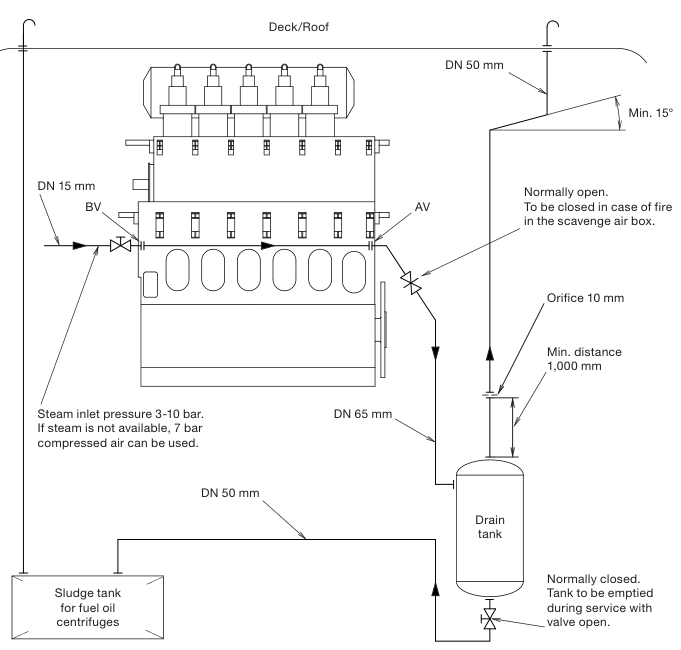
System Components & Operating Philosophy
- Under-Piston Sloped Floor Plates: The diaphragm plate separating the scavenge receiver from the crankcase is inclined toward drain wells located at the forward and aft ends of each cylinder unit to prevent puddle stagnation during ship pitch and roll.
- Sampling / Test Cocks & Sight Glasses: Each cylinder unit is equipped with an individual drain branch containing an inspection cock and sight glass. Watchkeepers physically inspect the color, viscosity, and quantity of discharge every watch (typically every 4 hours in UMS mode before leaving the machinery space unattended).
- Non-Return Valves (NRVs): Fitted in the main drain collection headers to prevent pressure surges, scavenge air back-flow, or toxic vapors from migrating between cylinder units or back from the drain tank into an idle cylinder.
- Scavenge Drain Sludge Tank: A dedicated double-bottom or cofferdam tank equipped with steam heating coils (maintaining sludge at 50°C–60°C for pumpability), high-level float alarms, and venting led to the funnel casing.
- Steam Flushing / Cleaning Connections: Fitted with 3–10 bar auxiliary steam lines to clear hardened carbon deposits and tar blockages from the drain lines during port stays or major overhauls.
| Operational State | Visual Appearance of Scavenge Drain Discharge | Underlying Cylinder Condition & Action Required |
|---|---|---|
| Normal Operation | Clear to dark brown, moderately viscous oil flowing in small, steady trickles; minimal carbon grit. | Cylinder lubrication feed rate balanced; normal ring-liner tribological interface. |
| Over-Lubrication | Copious golden-to-brown oil flow accumulating rapidly in sight glass; low viscosity, minimal solids. | Lubricator feed rate set too high; risk of hydraulic carbon packing in ring grooves. Reduce Alpha/Pulse feed rate by 0.05–0.1 g/kWh. |
| Combustion Blow-By | Thick, jet-black viscous sludge packed with gritty carbon particles; discharge smells of fuel combustion products. | Piston rings stuck, broken, or severely collapsed. Gas leakage blowing past rings into scavenge space. Immediate cylinder unit overhaul required. |
| Fuel Injector Leaking | Thin, pungent, black liquid smelling strongly of heavy fuel oil; flash point significantly reduced. | Fuel injector nozzle dribbling or cracked atomization tip. Cut fuel pump / change injector immediately to prevent scavenge puddle ignition. |
| Choked / Blocked Drain | Zero discharge through sight glass while adjacent units have steady flow; drain pipe cold to touch. | Hard carbon blockage in drain bore. Clear immediately using manual clearing wire or low-pressure steam blowing; pooling oil creates imminent fire hazard. |
4. Emergency Operational Protocol & Smothering Systems
When a scavenge fire occurs, every second counts. The watchkeeping engineer must execute a precise, drilled sequence of operational actions to prevent the fire from escalating into an iron fire, avoid turbocharger explosion, and protect engine room personnel.
Step-by-Step Emergency Action Protocol
- Inform Bridge & Chief Engineer: Notify the officer of the watch (OOW) on the bridge immediately that engine RPM will be reduced and engine may be stopped. Sound the engine room fire alarm if flames or heavy smoke are observed outside the receiver.
- Reduce Engine Speed & Load: Immediately pull back the fuel lever / governor command to Slow Ahead or Dead Slow Ahead. This reduces oxygen throughput from the turbochargers and lowers peak cylinder combustion temperatures.
- Cut Fuel to Affected Cylinder: Lift the fuel pump roller / puncture valve or electronically cut off fuel injection via the Engine Control System (ECS) to the affected cylinder. This eliminates the source of flame blow-by while keeping the engine rotating under partial load if navigating restricted waters.
- Increase Cylinder Lubrication to Affected Unit: If the engine continues to turn, increase the cylinder lubricating oil feed rate to maximum on the affected unit (or switch lubricator to emergency manual stroke). This lubricates the dry, overheated liner walls and prevents piston micro-welding or catastrophic seizure while the engine decelerates.
- Close Scavenge Drains: Immediately close the scavenge drain valves for the affected unit and the entire manifold. This prevents the fire from spreading down the drain headers into the scavenge sludge tank and prevents air ingress from open test cocks.
- Stop Auxiliary Blowers: Switch the electric auxiliary scavenge blowers from AUTO to OFF. Allowing auxiliary blowers to run pumps fresh oxygen directly into the seated fire, acting like a giant blacksmith's bellows.
- Engage Fixed Smothering Medium (If Fire Does Not Subside): If scavenge trunk temperatures continue to climb above 100°C–120°C or paint begins blistering, stop the main engine completely, engage the turning gear (do not engage until engine is stationary), maintain jacket cooling water and piston cooling oil circulation to absorb radiant heat, and discharge the fixed extinguishing system.
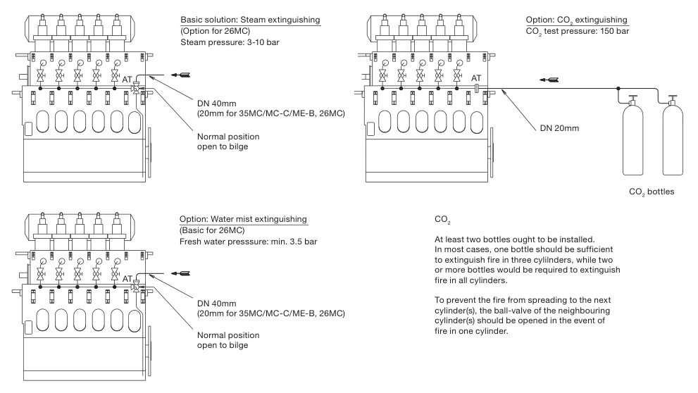
MAN B&W Maker Installation & Extinguishing Specifications
According to MAN B&W two-stroke engine design rules, the fixed scavenge space fire extinguishing installation is engineered with strict technical parameters:
- Steam Smothering: Standard arrangement operating at 3 to 10 bar boiler saturated steam via DN 40 mm distribution piping (DN 20 mm for small-bore engines such as S26MC, L35MC). The manifold drain line must remain normally open to the bilge to prevent water hammer and moisture accumulation.
- Carbon Dioxide (CO2): At least two dedicated CO2 cylinders must be fitted in the engine room or local station. Maker sizing rules mandate: one bottle is sufficient to extinguish a fire in up to three cylinders; two or more bottles are required for all cylinders simultaneously.
- Adjacent Cylinder Barrier Isolation: When extinguishing a scavenge fire in an affected cylinder using CO2 or steam, MAN B&W directs that the ball valves of the neighbouring cylinders must also be opened to establish an inert boundary zone, preventing fire propagation along the scavenge trunk.
- Cooling & Turning Discipline: Jacket cooling water and piston cooling oil circulation must be maintained continuously to carry away residual heat. The engine must be turned periodically with turning gear (only after coming to a complete stop) to prevent thermal bowing and piston crown seizure in the liner.
Comparison of Fixed Extinguishing Media
| Extinguishing Medium | Operating Parameters | Advantages & Limitations |
|---|---|---|
| Carbon Dioxide (CO2) | High-pressure bottles (50–60 bar) routed via dedicated scavenge fire pull boxes. Typically 1 to 2 bottles allocated specifically for scavenge trunk volume. | Advantages: Rapidly suffocates fire by lowering O2 below 12%; non-corrosive, leaves no residue. Limitations: Limited cooling capacity; if scavenge receiver doors are opened prematurely before metal cools below auto-ignition temp, fire reignites instantaneously. |
| Saturated Steam | 3 to 10 bar auxiliary boiler steam routed via dedicated manifold and non-return valves. | Advantages: High volume expansion (1 kg steam ≈ 1.6 m³ at atmospheric pressure); displaces air and provides moderate evaporative cooling. Limitations: Introduces moisture into scavenge space; steam condensation forms acidic condensate with combustion sulfur oxides, attacking liner surfaces. |
| High-Pressure Water Mist | Freshwater system operating at 60–140 bar delivering micro-droplets (50–150 μm) through cyclonic spray nozzles. | Advantages: Superb latent heat cooling (2260 kJ/kg absorption), rapid thermal quenching, suppresses reignition effectively. Limitations: Risk of thermal shock to red-hot cast iron liners if sprayed unevenly; requires high-pressure freshwater pumps and nozzle integrity. |
5. Prevention of Secondary Explosions & Door Opening Protocols
The single most hazardous mistake an engineering crew can make during a scavenge fire is prematurely opening the scavenge inspection doors. This has historically caused fatal engine room explosions due to the classical backdraft phenomenon.
The Backdraft Phenomenon in Scavenge Receivers
When a scavenge fire consumes the available oxygen inside an isolated, stopped engine receiver, active flaming combustion ceases and transitions into smoldering, oxygen-starved pyrolysis. The enclosed space fills with superheated hydrocarbon gases, vaporized lube oil, and carbon monoxide (CO) at temperatures far above their auto-ignition threshold.
If an engineer unbolts and opens a scavenge inspection door while this condition persists:
- Fresh, atmospheric air (21% O2) rushes into the low-pressure, oxygen-depleted receiver.
- The incoming oxygen mixes instantly with the superheated, combustible pyrolysis gases.
- The gas mixture enters its explosive range (typically 1.5% to 7.5% hydrocarbon vapor concentration by volume).
- Instantaneous deflagration occurs, projecting a massive fireball through the door opening directly into the engine room, killing watchkeepers and initiating widespread secondary fires.
| Safety Rule | Mandatory Protocol | Technical Rationale |
|---|---|---|
| Cooling Wait Period | Maintain engine stopped, keep jacket water circulating, and wait a minimum of 30 to 45 minutes after all temperature indicators have returned to ambient before unbolting doors. | Ensures internal metal surfaces (liner, piston crown, diaphragm) have cooled below the auto-ignition temperature of lube oil vapors (approx. 250°C–280°C). |
| Turning Gear Operation | Engage turning gear and turn the engine slowly as soon as the fire is smothered, provided no seizure has occurred. | Prevents asymmetric thermal bowing of the crankshaft, warping of the cylinder liner, and thermal binding of the piston rings inside the liner bore. |
| PPE & Door Opening Stand-Off | Wear full firefighting gear, helmet with visor, and heat-resistant gloves. Stand completely clear of the door swing arc when loosening bolts. | Loosen the door hinge-side bolts last; crack the opposite edge open by only 1–2 mm using a pry bar while observing for smoke, flame, or air inrush. |
| Atmospheric Gas Testing | Test internal atmosphere with a calibrated multi-gas detector for O2 deficiency, toxic CO, and combustible hydrocarbon vapor percentage before full entry. | Enclosed space entry rules (IMO Res. A.1050(27)) apply strictly to scavenge receiver entry. |
6. Scavenge Space & Trunk Relief Valves: Design, Metallurgy & Classification Rules
Because scavenge receiver fires and sudden gas deflagrations generate rapid internal pressure pulses, international classification societies (IACS Unified Requirement M9, SOLAS II-1/31, DNV, Lloyd's Register) mandate the installation of spring-loaded explosion relief valves on scavenge receivers and under-piston trunks.
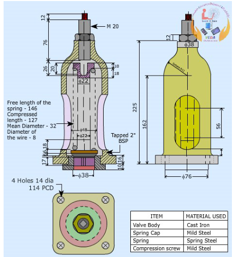
Engineering Design & Operating Mechanics
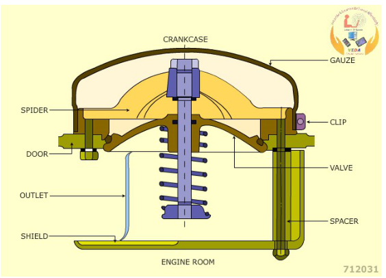
- Opening Pressure Calibration: The valve disc is held closed by a precision helical spring calibrated to lift at an overpressure of 0.2 to 0.3 bar gauge (approx. 0.02–0.03 MPa) above normal scavenge receiver pressure.
- Low Inertia Valve Disc: Manufactured from lightweight, non-sparking materials (aluminum alloy or high-grade bronze). High inertia would cause opening delay during supersonic pressure wave arrival, resulting in receiver structural rupture.
- Rapid Reseating Mechanism: As soon as the overpressure wave vents, the calibrated spring forces the disc back onto its soft neoprene/Viton O-ring seat within milliseconds. This rapid reseating prevents the ingress of fresh atmospheric oxygen into the scavenge trunk, eliminating the risk of a catastrophic secondary explosion.
- Flame Arrestor Wire Gauze Pack: Positioned on the internal (inlet) side of the valve disc. Constructed from multi-layered brass or stainless steel woven wire mesh (typically 0.3 mm wire diameter with 0.5 mm aperture). The gauze quenches exiting flame fronts through extreme surface-to-volume heat conduction, cooling escaping gases below their ignition temperature.
- Directional Deflector Hood / Cowl: Mounted on the external discharge casing, designed to deflect hot vented gas, burning soot, and pressure blast downwards at an angle of 30°–45° toward the engine deck plates, protecting passing engineers from direct horizontal burns.
Classification Relief Area Sizing (IACS UR M9)
Atotal ≥ VtrunkK
Where Atotal is the cumulative aggregate free relief area of all fitted relief valves (cm²), Vtrunk is the gross internal volume of the scavenge receiver (m³), and K is an empirical classification factor (typically K ≈ 8.5 to 11.5 cm²/m³ depending on engine cylinder bore and receiver geometry).
7. Post-Fire Assessment, Overhaul & Return-to-Service Checklist
Following complete extinguishment and controlled cooling of a scavenge fire, the engine must undergo a rigorous, systematic inspection before any attempt is made to restart or bring load back onto the propulsion plant.
| Component | Inspection Procedure | Acceptance Criteria & Failure Thresholds |
|---|---|---|
| Cylinder Liner | Perform 8-point internal micrometer calibration along upper, middle, and scavenge port levels. Inspect for vertical micro-cracks, bore glazing, and scuffing marks using dye-penetrant testing. | Maximum allowable ovality / out-of-roundness ≤ 0.1% of nominal bore. No deep scoring or heat-check network cracks permitted. |
| Piston Crown & Rings | Check piston crown top surface for burning, thermal erosion, or crown cracking. Measure piston ring axial clearance in grooves using feeler gauges; verify radial tension and ring gap. | Rings must move freely in grooves with spring-back intact. Replace collapsed, burnt, or stuck rings; clean carbon packing from ring lands. |
| Piston Rod & Stuffing Box | Inspect piston rod surface for blueing (indicating thermal distortion >300°C) and run-out using a dial gauge on turning gear. Dismantle stuffing box; inspect scraper rings and garter springs. | Rod run-out ≤ 0.05 mm. Scraper ring knife-edges sharp; garter spring tension intact; drain orifices completely cleared. |
| Diaphragm Plate | Inspect the bottom horizontal plate separating scavenge space from crankcase for thermal warpage, weld seams cracking, and gasket deterioration. | Zero distortion; hermetic oil-tight and gas-tight seal maintained to protect crankcase from gas blow-through. |
| Receiver Structural Walls & Relief Valves | Check receiver doors for planarity; replace burnt rubber sealing cords. Dismantle all scavenge relief valves; clean wire gauze with solvent; verify free spring travel. | Relief valve discs free of carbon gumming; wire gauze clean and unobstructed; new high-temperature neoprene/silicone door gaskets installed. |
| Crosshead & Guide Shoes | Check guide clearances and verify that lube oil supply to crosshead bearings was not interrupted by localized thermal distortion of the 'A' frame. | Crosshead guide clearances within manufacturer tolerances (±0.05 mm); no metal pick-up or wiped white metal. |
Standards & sources referenced
- SOLAS: International standards for the safety of life at sea.
- Conventions index
Practise this in the question bank
- Engine Room General (motor) — 24 questions
Found a mistake, or something unclear?
Report it in a few seconds — it goes straight to the editors.
- Safe Engine Room Watchkeeping: UMS Certification, Physical Rounds, Automation Safeguards & Emergency Response
- Engine Protections, Vibration Watch & Performance Curves
- Marine Diesel Engine Starting & Running Troubles: Fault Trees, Knock Diagnosis & Emergency Response
- Crankcase Explosions, Oil Mist Detectors & Relief Valves
- Scavenge Fires, Trunk Safety & Relief Devices