
Boiler Safety Devices and Emergency Response
Every protection corresponds to an accident that has already happened to someone else — bypassing one removes the warning, not the hazard.
Key Principles at a Glance 8 points
- If you cannot trust the protection, you cannot run the boiler — a bypassed trip removes the barrier between the hazard and the accident, not the hazard itself.
- The alarm must precede the trip; if they operate together, the warning function has been lost and that is a defect to report.
- Low water is a cooling problem: metal temperature rises within seconds, the tube bulges and ruptures, and cold feed into uncovered tubes can rupture a merely distorted tube.
- An improved high-lift safety valve uses a floating ring and steam passage to gain effective area once lifted, so it discharges full capacity quickly instead of creeping open.
- Chatter is rapid movement with seat contact; flutter is rapid movement without full seat contact — both damage the valve.
- Gag one safety valve at a time, never both, and count the gags and valves before returning to service.
- Furnace explosion prevention is entirely procedural and mechanical: purge fully, prove the igniter, prove the flame, close the fuel valve fully, and never relight without a full purge.
- A passing blowdown valve produces the same symptoms as a tube leak — check the blowdown valves and drain line temperature before assuming tube failure.
1. Why the protections exist
Every boiler protection corresponds to an accident that has already happened to someone else. Low-water trips exist because boilers have exploded when tubes were uncovered. Flame-failure trips exist because furnaces have exploded when unburnt fuel accumulated. Safety valves exist because pressure vessels have burst.
This means two things for the engineer:
- The protection is not an inconvenience. It is the accumulated experience of the industry.
- A protection that is bypassed does not remove the hazard. It removes the barrier between the hazard and the accident.
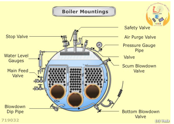
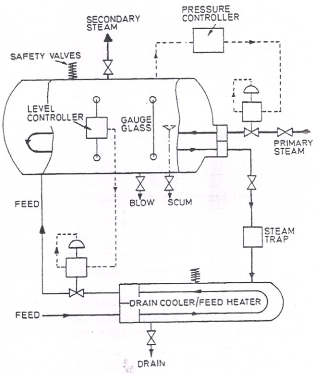
The steam-to-steam generator arrangement shows the protection boundary in one drawing: pressure controller, level controller, safety valves, gauge glass, feed and steam connections. Treat every start-up and every watch round as a check that each item in that boundary is present and working.
If you cannot trust the protection, you cannot run the boiler.
2. Water level protection
Water level is the single most important boiler measurement. Water cools the heated tubes; if the tubes are uncovered, the metal temperature climbs within seconds and the tube can fail.
2.1 Gauge glasses
At least two independent direct-reading water level indicators are normally required, fitted to the drum, together with remote indication in the control room.
Each gauge glass has:
- Steam cock — connects the glass to the steam space.
- Water cock — connects the glass to the water space.
- Drain cock — at the bottom, for blow-through.
- Protection device — often a glass ball or a ball valve that seats itself if the glass breaks, limiting the escape of steam and water. Where fitted, it must be free and correctly positioned, and its effectiveness must be confirmed.
The glass works because the steam and water columns in the glass reflect the drum. For that to be true, both the steam and water passages must be clear. A partially blocked passage shows a slowly responding or inaccurate level.
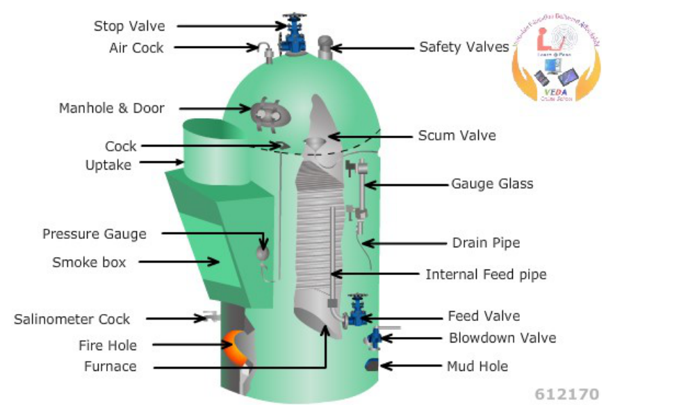
The mounting detail: gunmetal bodies with steam cock to the steam space, water cock to the water space, drain cock at the bottom, plate guards against shattering, and plugs for glass renewal. The blow-through sequence in 2.2 proves each of these passages in turn.
2.2 Blowing through a gauge glass
The purpose is to prove that the steam passage, the water passage, and the drain are all clear, and that the glass refills correctly.
Sequence (as commonly used):
Note the current level, so you know what it should return to.
Open the drain cock. Steam and then water should blow through, and the glass should clear.
Close the water cock. Steam only now blows down through the drain, clearing the steam passage and proving the steam connection.
Close the steam cock. The glass is now isolated with the drain open.
Open the water cock. Water blows down through the drain, clearing the water passage.
Close the drain cock.
Open the steam cock. The glass should refill and settle at the true level.
Compare with the other glass and with the remote indication.
What the behaviour tells you:
| Observation during blow-through | Meaning |
|---|---|
| Glass will not clear when steam cock is closed and water cock open | Water passage blocked |
| Glass will not clear when water cock is closed and steam cock open | Steam passage blocked |
| Water does not blow through when only the water cock is open | Water passage or connection blocked |
| Steam does not blow through when only the steam cock is open | Steam passage or connection blocked |
| Glass refills slowly, or fills only partly | Passage partially blocked; connection or cock restriction |
| Glass refills to a different level from the other glass | One of the two glasses is wrong; investigate before acting |
If a glass cannot be proven clear, the boiler must not be relied on for level indication until it is fixed.
2.3 Level alarms and cut-outs
Typical protection arrangements:
- High water level alarm — warns of overfilling, which leads to carryover.
- Low water level alarm — warns of an approach to the dangerous condition.
- Low-low water level cut-out — stops the burner before the tubes are uncovered.
- Very high level alarm and cut-out where fitted — prevents gross carryover.
The sequencing matters. The alarm must precede the trip, so the operator has warning. If the alarm and the trip operate together, the warning function has been lost, and that is a defect to report.
2.4 Why low water is so dangerous
When tubes are uncovered:
- The metal loses its water-side cooling.
- Metal temperature rises rapidly — the heat flux in a furnace wall is high enough to raise the temperature of a dry tube by hundreds of degrees in a very short time.
- The steel loses strength as it heats.
- The tube bulges and then ruptures under boiler pressure.
- The released water and steam flash to a large volume, and in a fire-tube boiler the whole water content can be released almost instantly, which is catastrophically destructive.
Cold feedwater hitting a red-hot tube causes sudden contraction, which can rupture the tube that was merely distorted. The correct action is to secure firing and let the boiler cool according to the procedure; the feed decision depends on the boiler design and the procedure.
3. Pressure protection
3.1 The pressure gauge
- Fitted with a siphon or cooling arrangement, so hot steam does not reach the Bourdon tube.
- Marked with the working pressure and a red line at the limit.
- Read at every round and compared with other indications.
A pressure gauge is a single point of failure for its own reading. Where a test gauge connection is provided, use it when accuracy matters, particularly for safety valve testing.
3.2 Safety valves
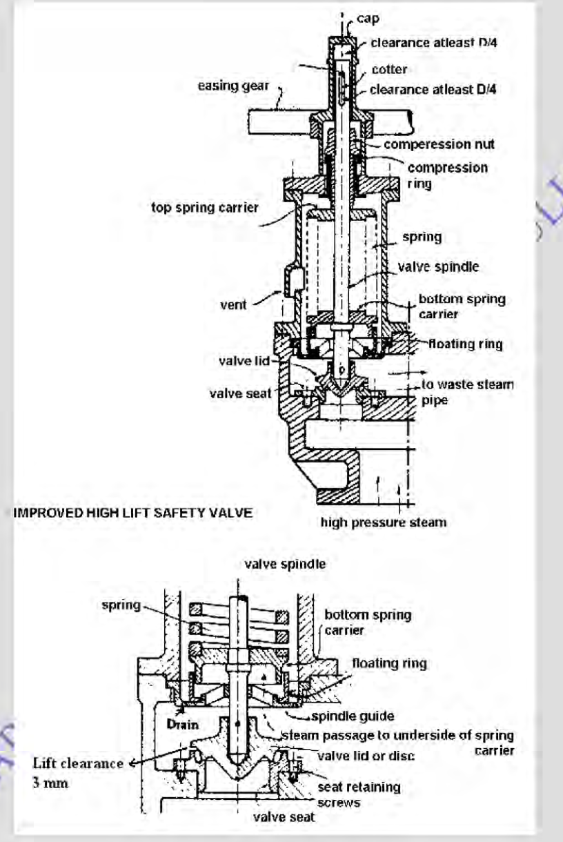
The drawing shows the parts to know: the valve lid or disc and seat, the spindle, the spring and its carriers, the floating ring, the easing gear, the compression nut, and the steam passage that takes pressure to the underside of the bottom spring carrier. The lift clearance and the D/4 clearance figures are the assembly checks made during overhaul.
How an improved high-lift safety valve works:
- Boiler pressure acts on the underside of the valve disc.
- When the spring force is overcome, the disc lifts from its seat.
- The floating ring and the steam passage to the underside of the spring carrier give the valve a larger effective area once it has lifted, so it opens further and more rapidly. This is what "high lift" means, and it is why the valve discharges its full capacity quickly rather than creeping open.
- The escaping steam is led to the waste steam pipe.
- The easing gear allows the valve to be lifted by hand for testing and for freeing a stuck valve.
The terms to know precisely:
- Set pressure — the pressure at which the valve begins to lift.
- Lift — the travel of the disc off its seat.
- Accumulation — the permitted rise in pressure above the set pressure while the valve is discharging at full capacity.
- Blowdown — the difference between the pressure at which the valve opens and the pressure at which it closes.
- Reseat (closing) pressure — the pressure at which the valve closes and flow stops.
- Chatter — rapid, abnormal reciprocating movement of the disc with contact with the seat. It damages the seat and disc.
- Flutter — rapid, abnormal reciprocating movement without full seat contact.
Why rapid and ample movement matters: the valve must relieve the boiler's full steaming capacity without the pressure rising beyond the permitted accumulation. If the valve opens slowly, or only lifts a small amount, the boiler pressure continues to rise while the valve is open. That is how a safety valve fails to protect.
3.3 Setting and testing a safety valve
Preparation:
Confirm the valve identity and its correct set pressure from the maker's data.
Confirm it was assembled correctly and that it lifted by D/4 when the spring tension was removed during overhaul.
Confirm the drain lines and waste steam pipes are clear.
Confirm a recently calibrated pressure gauge is connected to the boiler shell. It is usual to use two gauges to confirm the setting accurately.
Confirm the test procedure with the Chief Engineer and, where required, the surveyor.
Under-steam setting:
Bring the boiler to pressure with controlled firing and the boiler on light load.
Shut all inlet and outlet valves once the water level is stable. Open the feed inlet only as necessary to maintain level.
Gag one of the two safety valves — one at a time, using the approved procedure. Never gag both.
Raise pressure slowly on the ungagged valve.
Note the pressure at which the valve starts to lift.
Adjust the compression nut in small increments — a few turns at a time — and retest.
Confirm the lift pressure, then confirm the blowdown and the reseat pressure.
Confirm the valve will lift at no more than 103% of design pressure when firing continues.
Confirm that with the valve discharging, the pressure does not rise beyond 110% of design pressure, and that this condition can be held for the required period — commonly 7 minutes for a water-tube boiler and 15 minutes for a smoke-tube boiler.
Transfer to the other valve and repeat.
Record the distance from the bottom of the compression nut to the top of the safety valve cover bushes, so the setting can be restored after any future dismantling.
Remove the gags, fit the hood (locked to the spindle with a cotter key), fit the easing gear.
Lift each valve manually by the easing gear to confirm correct operation and freedom.
Count the gags and confirm every one is removed.
Log the set pressure, the test gauge reference and calibration date, and the person who performed the test.
When set in the absence of a surveyor, the Chief Engineer must forward a statement to the office in the required form, recording the settings and the test conditions.
3.4 Safety valve faults
| Fault | Cause | Consequence |
|---|---|---|
| Valve does not lift | Gagged; spindle seized; spring over-compressed; wrong adjustment | Boiler can be overpressurised |
| Valve lifts below set pressure | Spring weak or fatigued; wrong adjustment; seat damaged | Steam loss, frequent nuisance lifting |
| Chatter | Blowdown wrongly adjusted; obstructed discharge; valve undersized for the capacity | Rapid seat and disc damage |
| Flutter | Incorrect floating-ring clearance; spindle guide wear | Unstable discharge, damage |
| Leakage when closed | Seat damaged, dirt on the seat, misalignment | Continuous steam loss; further seat erosion |
| Will not reseat properly | Blowdown too small; sticking spindle; seat damage | Continuous steam discharge and pressure loss |
| Discharge pipe obstructed | Foreign matter; closed isolation valve; drain blockage | Valve cannot relieve; pressure rise |
And never leave one closed.
4. Combustion and fuel protection
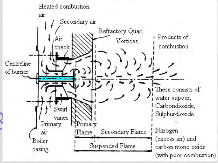
Correct combustion produces water vapour, carbon dioxide, sulphur dioxide, nitrogen, and the excess air that was supplied. Carbon monoxide in the products of combustion with poor combustion is the signal that the burner is not burning the fuel completely — and incomplete combustion is also what leaves unburnt fuel in the furnace.
4.1 Pre-purge
Before ignition, the furnace and gas path must be purged to remove any flammable mixture.
The purge must satisfy both the airflow requirement and the time requirement for the specific boiler. The airflow must be proven, not inferred from the fan running, and the purge must not be shortened or bypassed.
4.2 Flame failure protection
The flame scanner continuously proves that a flame exists.
On flame failure the burner management system must:
- Shut off the fuel immediately.
- Raise an alarm.
- Post-purge the furnace.
- Lock out until manually reset.
A masked or defeated scanner means the fuel can continue to enter a furnace with no flame, which is the classic preparation for a furnace explosion.
4.3 Fuel cut-off
The quick-closing valve must shut off fuel on:
- Flame failure.
- Low-low water level.
- High steam pressure.
- Loss of combustion air.
- Incorrect fuel temperature or viscosity.
- Emergency stop.
- Loss of control air or power, where applicable.
The valve must be tested to confirm it actually closes. A quick-closing valve that is slow, or that does not fully close, is a serious defect.
4.4 Atomising medium
Loss of atomising steam or air means the fuel cannot be broken into droplets. The result is a stream of unburnt fuel in a hot furnace. The burner must be secured on loss of atomising medium with the same discipline as on flame failure.
This is one reason why the atomising line has to be drained and warm before the burner is lit: wet atomising steam produces a poor spray, and cold steam will not atomise correctly at light-off.
4.5 Furnace explosion
A furnace explosion occurs when unburnt fuel accumulates in the furnace and gas path, and is then ignited.
How fuel accumulates:
- Incomplete pre-purge.
- Repeated ignition attempts with no purge between them.
- A fuel valve that leaks into the furnace when the burner is shut.
- Fuel admitted before the igniter is proven, or with no ignition.
- Flame failure with the fuel valve not closing properly, or with the fuel continuing to enter for any reason.
- Water in the fuel interrupting the flame while fuel continues to be supplied.
How ignition then occurs:
- The next ignition attempt.
- The hot refractory or hot metal surfaces igniting the accumulated mixture spontaneously.
- A glowing particle or a hot surface in the gas path.
Prevention is entirely procedural and mechanical:
Purge properly, every time, for the full period.
Prove the igniter before admitting fuel.
Prove the flame before releasing the firing rate.
Ensure the fuel valve closes fully and quickly.
Never attempt to relight without a full purge.
Never defeat the flame scanner or the purge logic.
4.6 Other combustion-related risks
- Burner dripping — fuel continues to enter after shutdown. Remove the burner, purge, and overhaul it. Do not simply light it again.
- Air register set wrongly — produces a long flame, poor mixing, smoke, and unstable combustion.
- Blocked or fouled gas path — raises furnace pressure, reduces output, and increases the risk of a soot fire.
5. Emergency response
5.1 Low water level
Recognise:
- Both gauge glasses low, or one low and the remote indication low.
- Low water level alarm.
- Falling level trend with feedwater unable to keep up.
Act:
Confirm the true level from both gauge glasses and the remote indication. An instrument fault and a real low level look identical until you check.
If the burner has not tripped and the level is genuinely at or approaching the low-low point, reduce or stop firing.
Do not feed unless the procedure allows. Cold feed into uncovered, overheated tubes can cause sudden contraction and rupture.
Establish whether water is available: feed pump running, feed tank level, feed valve position, discharge pressure.
Find the cause: feed pump, control valve, check valve, a leak, a passing blowdown valve, a level transmitter fault.
Report and log with times.
Do not return to service until the true level is established and the boiler condition is understood.
5.2 High water level and carryover
Recognise:
- Both glasses high.
- Water carryover in the steam — wet steam at the consumers, water hammer, unstable superheat.
- Conductivity or chloride readings rising if the cause is dissolved solids.
Act:
Confirm the true level.
Reduce feedwater flow; do not make a large single correction.
Reduce firing or load if necessary.
Increase blowdown as permitted, to reduce the dissolved solids driving the foaming.
Check the chemistry for high solids or oil contamination.
Check the steam line and drains for water hammer, and drain the line.
Check the steam separators at the next opportunity if the problem recurs with correct chemistry.
Oil contamination in the boiler water is a specific cause of foaming. The usual source is fuel oil heater coils or a lubricating oil leak. It must be found and repaired, and a coagulant may be used to break the oil out so it can be blown down.
5.3 Flame failure during running
Act:
Confirm the fuel has shut off and the alarm has sounded.
Allow the post-purge to complete.
Do not reset and relight without investigating.
Check: fuel pressure and temperature, viscosity control, burner condition, atomising medium, air supply and register position, flame scanner and sight tube, water in fuel, and any draught disturbance.
Obtain permission before restarting, and restart with the full sequence.
5.4 Tube leak
Recognise:
- Unexplained fall in water level.
- Increasing feedwater flow requirement for the same steam output.
- Falling steam pressure and output.
- White or wet appearance at the funnel.
- Steam or water escaping from the casing, inspection doors, or around the insulation.
- Abnormal noise inside the furnace — a roaring or hissing that changes with load.
- Feedwater flow persistently exceeding steam flow.
Act:
Reduce load and secure the boiler as instructed.
Confirm the fuel is shut off and allow the post-purge.
Isolate the boiler from the steam system.
Maintain correct cooling and draining within the procedure. Cool naturally; do not force-cool, and do not dump water into a hot boiler.
Do not open the boiler until it is depressurised and cool.
Inspect and identify the failure mechanism before repair — the mechanism determines whether it is an isolated fault or a systematic problem.
Note the distinction: a passing blowdown valve produces the same symptom as a tube leak — increased feedwater demand and a falling level. Check the blowdown valves and their drain line temperature before assuming a tube failure.
5.5 Soot or uptake fire
Recognise:
- Rapidly rising uptake or flue-gas temperature.
- Sparks or visible flame at the stack.
- The stack itself getting hot, or glowing.
- A smell of burning soot.
- Local hot spots on the casing or the stack.
Act:
Reduce or stop firing as the procedure requires.
Do not soot blow into a hot fire.
Apply the approved fire-fighting method — commonly steam smothering through the soot blowers or a fixed arrangement.
Provide boundary cooling to the uptake and stack where instructed.
Do not restart until the boiler has been inspected, the deposit removed, and the cause of the excessive deposit addressed.
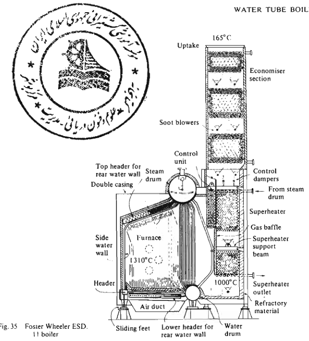
The deposit that burns sits on these gas-path surfaces — generating tubes, superheater and economiser sections served by the soot blowers. A rising uptake temperature logged over days is the warning that this deposit is building before it ignites.
Note the risk with steam: in a very hot deposit, steam can dissociate and the resulting hydrogen can feed the reaction. The procedure for the specific plant must be followed, and the decision to use steam depends on the fire's stage and temperature.
5.6 Economiser fire
Recognise:
- Rising economiser outlet gas temperature.
- Steam or smoke from the casing in the economiser area.
- Popping, rumbling, or thumping from the economiser.
- A change in draught, sometimes a sudden increase as the fire alters the gas path.
Act:
Secure firing.
Keep feedwater passing through the economiser where the procedure requires it, so the tubes stay cooled.
Use the approved extinguishing method.
Inspect before returning to service; check for tube damage, distortion, and deposit.
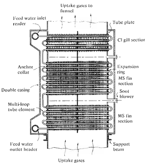
The economiser fire starts on this surface: feedwater tubes in the gas path that should be heating water, not collecting combustible deposit or steaming. Keep feedwater flowing through it during the emergency so the tubes stay cooled, and inspect every element for distortion before returning to service.
5.7 Water hammer
Recognise:
- Heavy banging or hammering in the steam line, superheater, or economiser.
- Pipe movement and support damage.
- Pressure spikes.
Causes:
- Condensate in a cold steam line, or in a line that has been allowed to cool with the drains closed.
- Opening a steam valve too rapidly.
- Economiser steaming, which traps steam in the tubes.
- Carryover from the drum adding water to the steam.
Act:
Reduce or close the steam valve.
Drain and warm the line properly before reopening.
Check the drum level and the chemistry for carryover causes.
Check the economiser feedwater flow and temperature for steaming.
Inspect for damage before returning to normal operation.
5.8 Loss of combustion air or forced-draught fan
Act:
The burner must trip on loss of combustion air — confirm that it has.
Do not reset while the airflow fault exists.
Check the fan, its power supply, the damper, the air path, and the airflow proving device.
Confirm the furnace has been purged before any attempt to relight.
6. Emergency action summary
| Emergency | First action | Dominant risk if mishandled |
|---|---|---|
| Low-low water level | Stop firing; confirm level; do not feed unless the procedure allows | Tube rupture from overheating, or from thermal shock on refilling |
| High water level / carryover | Reduce feed; reduce load; increase blowdown | Water hammer, turbine and superheater contamination |
| Flame failure | Confirm fuel off; post-purge; find the cause | Furnace explosion |
| Unburnt fuel in the furnace | Do not ignite; purge fully; investigate | Furnace explosion |
| High steam pressure | Reduce firing; confirm control and safety valve operation | Pressure-part failure |
| Safety valve lifting continuously | Check actual pressure; check controller; check outlet | Overpressure if the cause is not found; loss of water and heat |
| Tube leak | Secure boiler; isolate; cool correctly | Burn and scald risk; secondary tube damage |
| Soot or uptake fire | Stop firing; approved smothering; boundary cooling | Fire spread through the uptake and casing |
| Economiser fire | Secure firing; keep cooling flow; extinguish | Tube failure and fire spread |
| Water hammer | Reduce or close the valve; drain and warm | Pipe, support, and fitting rupture |
| Loss of atomising medium | Secure the burner | Unburnt fuel accumulation |
| Loss of control air or power | Confirm the burner trips; investigate before reset | Loss of combustion control |
7. The discipline that prevents the emergency
Most boiler emergencies are the end of a chain that started earlier and was visible earlier.
- A rising uptake temperature was logged for days before the soot fire.
- A tube leak that started as a small weep produced a slow rise in feedwater demand for weeks.
- A burner that was smoking for months finally caused a deposit that ignited.
- A safety valve that had been gagged for a survey was never ungagged.
The protections catch the last few seconds. The watchkeeping catches the preceding weeks. Both are needed, and the watchkeeping is the part that the engineer controls.
Non-negotiable rules:
Never bypass a protection to keep steaming.
Never leave a safety valve gagged or isolated.
Never run with a failed water level indicator.
Never open the furnace or uptake without the correct permit, isolation, and atmosphere test.
Never restart after an unexplained trip without finding the cause.
Record everything: time, indication, action taken, and who was informed.