

Steam Traps, Pressure Reducing Valves (PRVs) & Condensate Drainage
Master marine steam traps, pilot-operated pressure reducing valves (PRVs), thermodynamic disc traps, bimetal traps, water hammer physics, and steam line drainage for MEO examinations.
1. The Thermodynamics of Condensate & The Purpose of Steam Traps
Warning: The Value of Latent Heat
When fuel is burned in a marine auxiliary boiler, approximately 75% to 80% of the total thermal energy transferred to the water is stored as Latent Heat of Vaporization (hfg). If live steam blows through a heating coil without condensing, this enormous energy investment is dumped straight into the atmospheric drain tank, collapsing thermal plant efficiency.
A steam trap is an automatic valve engineered to distinguish between steam and condensate. Its fundamental marine duties are threefold:
Hold Back Live Steam
Ensure that steam remains inside fuel oil heating coils, fresh water generators, air heaters, and jacket preheaters until it has completely condensed, releasing its full latent heat (typically 2,000 to 2,200 kJ/kg).
Purge Condensate Instantly
Discharge condensed water immediately as it forms. Allowing condensate to back up inside heating tubes creates liquid waterlogging, slashes overall heat transfer coefficient (U-value) by up to 80%, and triggers severe corrosive carbonic acid pitting.
Vent Air & Non-Condensable Gases
Discharge air and carbon dioxide during plant startup. Air is a catastrophic thermal insulator; an air film just 0.025 mm thick offers the equivalent thermal resistance of an 85 mm steel pipe wall!
Classification of Marine Steam Traps
To operate reliably under marine conditions—including vibration, ship roll, varying boiler loads, and backpressure—marine steam traps are grouped into three primary thermodynamic classes, plus specialized pumping units:
- Thermodynamic Traps: Actuated by fluid velocity and Bernoulli dynamic pressure drops (floating disc).
- Thermostatic Traps: Actuated by the temperature differential between live steam and subcooled condensate (bimetallic elements and liquid-expansion bellows).
- Mechanical Traps: Actuated by fluid density differences between steam and liquid water (inverted bucket and ball float).
- Automatic Pumping / Vacuum Traps: Mechanical float-operated pumping chambers that use motive steam to lift condensate out of low-pressure or vacuum spaces.
2. Thermodynamic Disc Traps — The Bernoulli Operating Cycle
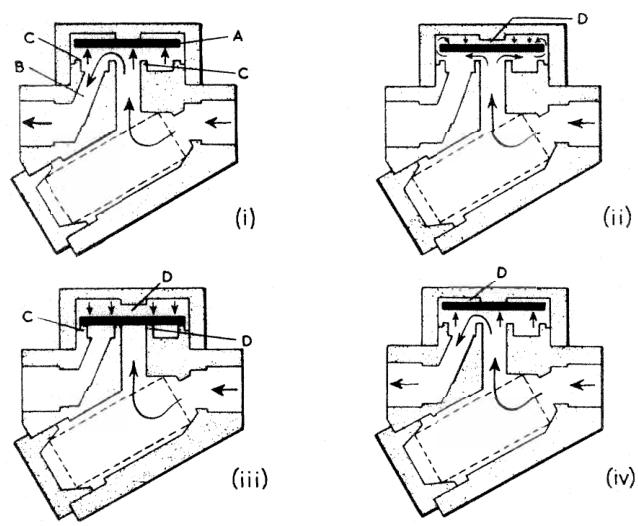
The thermodynamic disc trap (exemplified by the classic Spirax-Sarco TD series) is the workhorse of marine steam systems. Compact, robust, and virtually immune to water hammer and vibration, it contains only one moving part: a hardened stainless steel circular disc resting freely on two concentric seating rings.
Detailed Step-by-Step Physics of the Bernoulli Cycle
- Phase 1 (Cold Startup & Condensate Flow): On startup, incoming cold condensate and air exert hydrostatic pressure against the underside of disc A. The disc lifts easily off concentric seat rings C, discharging water directly through central inlet orifice B and outer annular discharge ports.
- Phase 2 (Flash Steam & Dynamic Pressure Collapse): As water reaches near-saturation temperature, the pressure drop across the seating orifice causes hot condensate to suddenly flash into live vapor. Steam has over 1,000 times the specific volume of water; its radial velocity under the disc accelerates tremendously. By Bernoulli's Principle:
Pstatic + ½ρv² = constant
As velocity v skyrockets radially outward toward the outlet ports, localized static pressure underneath the disc plummets. This pressure depression pulls the disc downward toward the seating faces. - Phase 3 (Snap Closure by Area Differential): Concurrently, high-pressure flash steam curls around the outer perimeter of the disc into control chamber D above the disc. The closing force acting downwards is:
Fclose = Pchamber × Adisc, full
While the opposing upward opening force is only:Fopen = Pinlet × Ainlet, central
Because the full upper surface area of the disc is roughly 3 to 5 times larger than the tiny central inlet orifice, Fclose dramatically overpowers Fopen. The disc snaps shut instantly and violently. This instantaneous snap action eliminates wire-drawing of the precision seating rings. - Phase 4 (Heat Dissipation & Cycle Reset): The trap remains tightly sealed. Live steam trapped in upper control chamber D gradually dissipates heat through the top cap into the surrounding machinery space atmosphere. As the chamber steam cools and condenses into a minute droplet, chamber pressure drops below line pressure. The inlet pressure lifts the disc again, and the cycle repeats.
Practical Watchkeeping Tip
A healthy thermodynamic trap operating on a marine heating line exhibits a sharp, rhythmic "click ... snap" every 15 to 30 seconds. If it clicks continuously at machine-gun speed (several times per second), the disc or seat is severely wire-drawn, blowing live boiler steam straight into the condensate returns.
3. Thermostatic & Mechanical Steam Traps
While thermodynamic traps are rugged and simple, they cannot subcool condensate or operate under deep vacuum. Thermostatic and mechanical traps are preferred for cargo heating coils, air heaters, and galley steam tables.
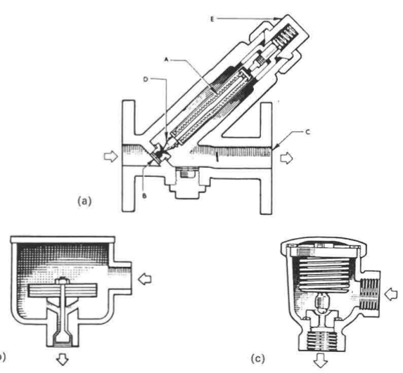
Thermostatic Trap Architectures
Bi-Metallic Strip Trap
Utilizes thermally bonded strips of two metals having different coefficients of thermal expansion (e.g. invar and nickel-chrome steel). As hot steam enters, the strip flexes into a curve, driving valve head D against orifice B. Highly resistant to water hammer and superheated steam.
Balanced-Pressure Bellows Trap
Contains a corrugated bronze or stainless steel capsule filled with a special water-alcohol liquid mixture that boils a few degrees lower than pure water. Internal bellows vapor pressure always matches external line pressure, naturally self-compensating over wide pressure fluctuations.
Oil-Filled Expansion Trap
An internal sealed cylinder filled with mineral oil expands volumetrically when heated, driving a central stem toward the valve seat. Adjusted via setting screw E to release condensate at a fixed subcooled temperature (e.g. 80°C).
Mechanical Traps: Density-Driven Condensate Discharge
Mechanical steam traps do not rely on temperature drops or fluid velocity; they open and close strictly in response to the buoyant force exerted by liquid water:
- Ball Float Trap with Thermostatic Air Vent: A hollow stainless steel sphere is connected via lever arms to a discharge needle valve. As condensate enters the body, the float rises, opening the orifice proportionally to discharge water continuously at exact saturation temperature. An auxiliary balanced-pressure capsule in the upper body automatically purges trapped air on startup.
- Inverted Bucket Trap: An open-bottom cylindrical bucket hangs inside the trap body. When steam enters beneath the bucket, it displaces water and makes the bucket buoyant, snapping the top valve shut. As steam condenses or bleeds through a tiny vent hole in the bucket top, the bucket loses buoyancy, sinks, and yanks the discharge valve wide open. Excellent for high-pressure superheated lines.
| Trap Type | Operating Principle | Resistance to Water Hammer | Discharge Behavior | Primary Shipboard Application |
|---|---|---|---|---|
| Thermodynamic Disc | Bernoulli dynamic pressure drop & flash steam area differential | Exceptional (all stainless steel, 1 moving part) | Intermittent cyclic snap (every 15–30 s) | Main steam line tracer lines, whistle drains, deck line manifolds |
| Bi-Metallic Strip | Differential thermal expansion of bonded metal alloys | Very Good (rugged leaf elements) | Continuous modulated discharge (subcooled) | Heavy fuel oil storage tank coils, deck tank cleaning heaters |
| Balanced Bellows | Vaporization of lower-boiling liquid capsule | Poor (bellows can rupture or crush) | Intermittent modulated discharge | Accommodation heating radiators, air handling units |
| Float & Thermostatic | Buoyancy of hollow stainless steel ball float | Moderate (float ball can collapse under shock) | Continuous steady flow matching condensate rate | Plate heat exchangers, FWG steam evaporators, lube oil purifiers |
| Inverted Bucket | Buoyancy of inverted open-bottom bucket | Good (sturdy bucket, water seal) | Intermittent cyclic gulping | High-pressure auxiliary boiler superheater header drains |
4. Automatic Pumping & Vacuum Traps
Warning: The Low-Pressure Condensate Stall Problem
When steam is throttled to very low pressures (or when condensing in fresh water generators operating under deep vacuum at -0.9 bar gauge), the pressure inside the heat exchanger is lower than the atmospheric backpressure in the condensate return main. In this stalled condition, conventional steam traps cannot discharge water—condensate floods the heating tubes, causing complete thermal collapse.
Pumping Trap Architecture & Internal Cycling
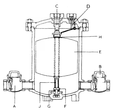
The automatic pumping trap (e.g. Royles or Spirax-Sarco Pivotrol) operates as a self-contained cyclic positive-displacement pump powered entirely by motive live steam:
- Filling Stroke (Exhaust Open, Steam Shut): When the internal chamber is empty, exhaust valve C is open to an equalizing vent pipe, and high-pressure steam valve D is held shut by permanent magnet G. Condensate drains freely by gravity from the low-pressure equipment through non-return valve A into the chamber.
- Snap-Action Trigger: As water fills the vessel, hollow float E rises. When the water reaches high level, the float compresses heavy spring H. Once the spring force overcomes the holding power of magnet G, spindle J snaps instantaneously upward.
- Discharge Stroke (Motive Steam Injection): The snap linkage instantly closes exhaust valve C and slams motive steam valve D wide open. High-pressure steam (typically 4 to 7 bar) enters the top of the chamber, driving the trapped liquid out through discharge non-return valve B into the overhead boiler feed tank.
- Cycle Reset: As the water level plummets, the falling float hits lower collar F, snapping spindle J downward. Steam valve D closes, exhaust valve C vents chamber pressure, and filling begins anew.
5. Pressure Reducing Valves (PRVs) — Pilot-Operated Diaphragm Design
Marine auxiliary boilers typically generate saturated steam at 16 to 20 bar gauge. However, secondary consumers—accommodation heating radiators, galley steaming kettles, fuel oil tank heating coils, and purifier preheaters—are rated for much lower design pressures (typically 2 to 4 bar gauge). Exposing these low-pressure heat exchangers to full boiler pressure would cause catastrophic tube rupture.
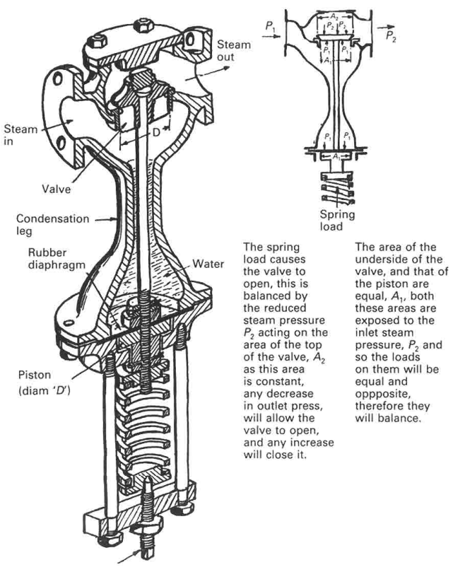
Pressure regulation is achieved through Pressure Reducing Valves (PRVs). While simple direct-acting spring-loaded valves exist for minor duties, major marine lines utilize pilot-operated diaphragm PRVs (such as the classic Spirax-Sarco DP17 or Hopkinson design).
Cross-Sectional Working Architecture
Detailed Step-by-Step Balancing Mechanism
- Initial State (Valve Closed): Prior to operation, main return spring pushes main valve disc up against its seat, keeping the high-pressure port isolated.
- Opening Demand: The top adjustment screw is turned down, compressing the setting spring against the upper face of the pilot diaphragm. The diaphragm flexes downward, unseating the small pilot valve.
- Piston Pressurization: High-pressure steam from inlet P1 flows through internal drillings past the open pilot valve into the chamber above the main operating piston. Because the piston area is much larger than the main valve disc, steam pressure pushes the piston down, forcing the main valve wide open against its return spring. Reduced steam flows into outlet P2.
- Dynamic Equilibrium: Downstream pressure P2 feeds back through the internal sensing port to the underside of the pilot diaphragm. When downstream pressure matches the spring setting:
P2 × Adiaphragm = Fspring
The diaphragm returns to neutral, throttling the pilot valve. This stabilizes the steam volume above the operating piston, holding the main valve at the exact opening percentage required to satisfy downstream flow demand. - Automatic Correction on Load Fluctuations:
- If downstream steam consumption drops, P2 instantly rises. The higher pressure pushes the pilot diaphragm UP against its spring, closing the pilot valve. Steam trapped above the operating piston bleeds past piston rings into downstream line; the main closing spring immediately strokes the main valve shut.
- If downstream consumption increases, P2 dips. The setting spring pushes the diaphragm DOWN, opening the pilot valve and forcing the main valve wider.
6. Steam Line Water Hammer Physics & Piping Design
Danger: The Lethal Threat of Water Hammer
Water hammer in marine steam pipelines is capable of generating instantaneous pressure spikes in excess of 100 to 150 bar. The catastrophic shock wave can shatter cast iron valve bodies, shear flange studs, rupture expansion bellows, and whip pipe hangers off bulkheads, releasing lethal live steam into occupied machinery spaces.
The Two Mechanisms of Steam Water Hammer
1. Slug Flow Impact (Hydraulic Shock)
If condensate pools in a sagging pipeline, high-velocity steam (traveling at 25 to 40 m/s) generates surface waves across the water pool. Once a wave bridges the pipe cross-section, the steam acts as a massive pneumatic piston, accelerating the liquid slug down the pipe until it slams into an elbow, valve, or blind flange.
2. Condensate-Induced Bubble Collapse (CIBC)
Occurs when a pocket of hot live steam is completely surrounded by subcooled condensate. Steam transfers heat rapidly and condenses instantaneously, causing its specific volume to collapse by a factor of 1,000 to 1,600. The surrounding water rushes inward into the sudden vacuum void; the liquid faces collide violently at sonic velocity, creating localized shockwaves.
Joukowsky Pressure Surge: ΔP = ρ · c · Δv
where ρ is liquid water density (1,000 kg/m³), c is acoustic velocity in water (~1,400 m/s), and Δv is the velocity change upon impact. An instantaneous slug deceleration from 30 m/s to rest yields a theoretical peak pressure surge of 42 MPa (420 bar)!
Piping Architecture Rules to Eliminate Water Hammer
- Pipe Gradient & Drainage Slope: Steam lines must never run perfectly horizontal. They must slope in the direction of steam flow with a fall of at least 1:100 (10 mm drop per meter of run).
- Full-Bore Collecting Pockets (Drip Legs): Condensate traveling at 35 m/s cannot drop into a tiny 15 mm hole drilled in the pipe bottom—steam simply blows water straight over it. A full-diameter collecting pocket (equal to pipe diameter up to 100 mm, and at least half pipe diameter for larger mains) must be fitted at all low points, line ends, and before vertical risers.
- Eccentric Reducers (Flat-on-Bottom): When pipe diameter reduces, concentric reducers create a bottom lip or dam that traps a deep pool of condensate. Eccentric reducers installed flat-on-bottom (FOB) must always be used on horizontal steam mains.
7. Condensate Return, Atmospheric Hotwell & Oil Contamination Safeguards
Condensate discharged from steam traps is not waste water; it is distilled, chemically conditioned boiler feedwater at temperatures between 70°C and 90°C. Returning this condensate to the boiler feed system saves enormous quantities of fuel and boiler treatment chemicals.
The Cascade Atmospheric Hotwell & Inspection Tank
Marine condensate returns drain by gravity into a multi-compartment Inspection Tank / Cascade Hotwell located in the engine room lower flats:
- Observation Sight Glass / Sight Hopper: Returns from cargo heating coils and bunker tank heaters pass through illuminated sight glasses or open tundishes. Watchkeeping engineers visually inspect the stream for traces of fuel oil sheen.
- Cascade Baffles & Filter Media: The inspection tank contains a series of over-and-under weir baffles packed with loofah sponges, coir mats, or synthetic coalescing filter elements. If a fuel coil pinhole develops, floating oil is trapped on the water surface and skimmed off before reaching the feed pump suction.
- Oil-in-Water Turbidity Monitors: Modern automated vessels utilize optical scattering oil-in-water sensors in the condensate return main. If hydrocarbons exceed 5 to 15 ppm, a pneumatic three-way divert valve dumps the entire condensate return overboard to the bilge holding tank or slop tank, sounding an alarm in the engine control room (ECR).
Danger: The Danger of Oil Entering the Auxiliary Boiler
If fuel oil passes through a leaking steam trap into the boiler, it forms an insulating greasy film on furnace crowns and generating tubes. Because oil has negligible thermal conductivity, the steel tube overheats rapidly, bulges under internal pressure, and suffers catastrophic tube rupture and boiler explosion.
8. Steam Trap Overhaul, Diagnostics & Surveyor Inspection
A systematic steam trap maintenance program prevents boiler fuel waste, preserves heating capability, and eliminates pipeline water hammer.
Non-Destructive Diagnostic Techniques
| Testing Method | Healthy Trap Indication | Defective Trap Indication (Failed Open / Failed Closed) |
|---|---|---|
| Ultrasonic Acoustic Tester | Rhythmic crisp clicking every 15–30 s (thermodynamic); steady whistling hiss (flow modulating) | High-pitched continuous shrieking = blowing live steam; total dead silence = blocked/failed shut |
| Infrared Thermography / Contact Pyrometer | Inlet at saturation temp; outlet shows expected temperature drop (ΔT of 10°C to 25°C for thermostatic traps) | Inlet and outlet temperatures identical = trap blowing live steam through; both cold = waterlogged/isolated |
| Three-Valve Test Tee Cock | Shut return isolation valve; open test cock. Intermittent discharge of water and flash vapor puffs | Continuous high-pressure dry blue steam jet = blown trap; zero discharge = blocked strainer/orifice |
Overhaul & Inspection Checklist for MEO Oral Exams
- Integral Strainer Screen: Unscrew the trap strainer plug; remove and clean the cylindrical stainless steel mesh. Scale, pipe rust, and welding slag account for over 70% of trap blockages.
- Disc and Seat Lapping: In thermodynamic traps, inspect the disc and seating rings for radial wire-drawing cuts. Light pitting can be lapped flat on a cast iron surface plate using fine silicon carbide diamond compound. If wire-drawn grooves are deep, replace both disc and seat assembly as a matched pair.
- Bellows Element Testing: Immerse thermostatic bellows capsules in a pot of hot water. Verify the valve head strokes outward smoothly; if the capsule remains compressed, the volatile fill charge has leaked out and the unit must be renewed.
- PRV Diaphragm & Orifice Cleaning: Strip pilot-operated reducing valves annually. Clean the miniature internal pilot sensing drillings with compressed air and nylon filament (never steel wire, which enlarges the calibrated pilot orifice). Inspect the phosphor bronze or stainless steel diaphragm for fatigue cracking.
Practise this in the question bank
- Piping & Hydraulics — 57 questions
Found a mistake, or something unclear?
Report it in a few seconds — it goes straight to the editors.
- Ship Pipelines — Seawater, Bilge, Ballast & Fuel Systems
- Globe, Gate & Non-Return (SDNR) Valves: Working, Troubleshooting & Overhaul
- Butterfly Valves: Working, Construction, Troubleshooting & Overhaul
- Sea Chests (High/Low Suction) & Marine Growth Prevention (MGPS)
- Sea Chest Strainers: Construction, Standby-First Changeover & Safe Cleaning
- Pipe Corrosion, Water Hammer & Failure Response
- Steam Traps, Pressure Reducing Valves (PRVs) & Condensate Drainage