

Centrifugal Cargo Pumps & Stripping Systems — Double-Entry Impellers, Steam Turbines and Vac-Strip
Master tanker cargo oil pumps: double-entry centrifugal pumps, steam turbine drives, pumproom bulkhead gas seals, Worthington-Simpson Vac-Strip, stripping pumps and eductors for MEO exams.
1. Tanker Discharge Architecture & The Pumping Warranty
Warning: The 24-Hour Commercial Warranty
Under standard tanker charter parties (e.g. Asbatankvoy, Shelltime), the shipowner warrants that the vessel can discharge its entire cargo within 24 hours, or maintain a back-pressure of 100 psi (approximately 7.0 bar gauge) at the ship’s manifold rail. Time lost beyond this allowance places the vessel on expensive demurrage, unless caused by shore line restrictions verified by an immediate Letter of Protest (LOP).
A Very Large Crude Carrier (VLCC) carrying 300,000 tonnes of crude oil must discharge at a combined volumetric rate of 12,000 to 15,000 m³/h. This massive flow is handled by three or four main **Cargo Oil Pumps (COPs)** located in a dedicated pumproom at the forward end of the engine room, adjacent to the cargo slop tanks.
Cargo reaches the pumps through one of three standard bottom piping networks:
Direct Pipeline System
The cargo block is segregated into 3 or 4 separate groups, each served by its own independent bottom line (typically 600–900 mm diameter) connected to one specific cargo pump. Ideal for parcel segregation on product carriers.
Ring Main System
A continuous loop pipeline runs around the outer cargo tanks with crossover lines and individual drop valves to each compartment. Offers maximum flexibility, allowing any pump to draw from any tank.
Free-Flow System
Eliminates long suction pipelines in large crude carriers. Large hydraulic sluice gates (600 × 800 mm) in transverse bulkheads allow oil to drain aft by gravity through the center tanks into the aftermost suction chest.
2. Centrifugal Cargo Oil Pump (COP) Construction
Prior to the adoption of high-capacity centrifugal pumps, tankers relied on reciprocating steam pumps. While reciprocating pumps self-prime readily, their physical size, massive weight, and numerous moving valves made handling thousands of tonnes per hour impossible.
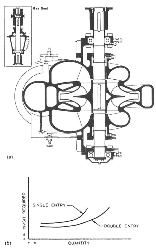
Why the Double-Entry Impeller is Universal
Almost all high-capacity centrifugal cargo pumps utilize a **double-entry (double-suction) impeller** where liquid enters simultaneously from both sides of a central dividing web into back-to-back vanes:
This construction gives two decisive advantages essential for tanker service:
- Perfect Axial Thrust Balance: Because fluid enters from both sides in equal volume (Q/2), the dynamic reaction forces acting against the impeller faces are equal and opposite, cancelling each other out completely. Heavy, heat-generating external thrust bearings are eliminated.
- Drastic NPSH Reduction: The inlet area of the impeller eye is effectively doubled. Halving the fluid approach velocity into the impeller eye slashes the required Net Positive Suction Head (NPSHr) by approximately 30% to 40%. This allows the pump to pull oil down to much lower tank levels before boiling and cavitating.
The pump casing is cast in bronze or ductile nodular iron, fitted with renewable leaded bronze or stainless steel **casing wear rings**. Radial clearances are maintained tightly at 0.30 to 0.45 mm to limit high-pressure discharge slip back into the suction eye.
3. The Engine Room Bulkhead Gas Seal
SOLAS Chapter II-2 and Classification rules strictly prohibit placing spark-generating electrical switchgear, high-temperature boilers, or non-certified electric motors inside a cargo pumproom. Therefore, the prime movers (steam turbines or electric motors) are located in the safe machinery space, driving the vertical pumps down in the hazardous pumproom through a transmission shaft penetrating the gas-tight division bulkhead.
The **bulkhead gland** must maintain absolute gas-tight and liquid-tight isolation under all operating conditions:
- Sealing Elements: Consists of two segmented carbon rings or self-aligning mechanical face seals enclosed within a bronze/cast-steel housing bolted to the watertight bulkhead.
- Fluid Lubrication & Barrier: The cavity between the two sealing faces is kept permanently flooded with lubricating oil from an elevated gravity reservoir. The liquid head prevents dry friction, cools the faces, and acts as a positive liquid barrier against hydrocarbon vapor transfer.
- Mandatory Thermal Monitoring: In compliance with SOLAS Reg II-2/4.5.10.1, the bulkhead gland is fitted with a continuously indicating temperature sensor (PT100 RTD). If gland temperature exceeds **65°C to 75°C** (indicating loss of lubricant or mechanical rubbing), an alarm sounds on the bridge and cargo control room, automatically initiating drive turbine trip.
- Flexible Cardan Shaft: Because the pump is anchored to the bottom pumproom floor and the turbine is seated on an engine room flat, dynamic hull flexing in seaways would cause severe misalignment. The vertical transmission shaft incorporates two flexible gear couplings or universal cardan joints with needle roller bearings.
4. Steam Turbine Drives & Governing Systems
Direct steam turbines are the traditional prime mover of choice for crude oil carriers. While electric motors require heavy electrical generators and explosive-gas interlocks, steam is inherently spark-free and readily generated in high volume by auxiliary water-tube boilers burning cheap heavy fuel oil.
A typical COP drive is a single-casing, horizontal or vertical **Curtis-wheel impulse turbine** developing 1,500 to 3,000 kW at 4,000 to 6,000 RPM, coupled to an epicyclic or parallel-shaft reduction gearbox stepping speed down to the pump's operating range of 1,200 to 1,800 RPM.
| Safety Protective Device | Trip Setting / Trigger Threshold | Actuation Mechanism & Action |
|---|---|---|
| Centrifugal Overspeed Trip | 110% to 115% of maximum rated RPM | An eccentric spring-loaded bolt in the rotor shaft flies out under centrifugal force, tripping the hydraulic latch and slamming the quick-closing Emergency Stop Valve (ESV) shut within 0.5 seconds. |
| High Exhaust Back-Pressure | Exceeding 0.5 to 1.0 bar gauge | Protects the turbine casing and condenser from bursting if the auxiliary condenser circulating pump trips or the main exhaust valve is mistakenly left closed. |
| Low Lubricating Oil Pressure | Falling below 0.8 bar | Spring-loaded diaphragm drops out, dumping turbine control oil and closing the throttle valve before whitemetal bearings wipe. |
| High Pump Casing Temperature | Exceeding 70°C to 80°C | Prevents hot casing surfaces from igniting volatile hydrocarbon cargo vapors in the event of dry-running cavitation. |
Turbine speed is governed across the pumping cycle by a hydraulic flyweight governor acting upon multi-nozzle control valves. As the discharge head changes during tidal swings or tank changes, the governor modulates steam admission to hold the selected pumping rate constant.
5. The Low-Level Draining Dilemma (Air Snoring & Cavitation)
A centrifugal pump operates at peak efficiency when drawing from a full cargo tank with a positive gravity head of 15 to 20 metres. However, as the liquid level drops to the final 1 to 2 metres above the tank bottom, severe physical obstacles emerge:
- Internal Hull Frame Impedance: Longitudinal girders, floor plates, and bottom frames act as internal dams. Crude oil flows sluggishly through small **limber holes** toward the aft suction bellmouth. The pump discharges oil faster than gravity can deliver it across the tank bottom.
- Vortex Formation: When liquid depth drops below approximately 2 to 3 times the bellmouth diameter, high surface velocity creates a hollow funnel vortex. Air and inert gas are drawn directly into the suction line from the cargo ullage space.
- Centrifugal De-Priming (Snoring): While positive displacement pumps tolerate two-phase fluid, a centrifugal impeller cannot pump air. Gas bubbles accumulate in the low-pressure impeller eye. The pump loses its prime, discharge pressure drops to zero, and the impeller churns in foam, leading to severe vibration and rapid overheating of casing wear rings and mechanical seals.
Traditionally, when a pump began "snoring," the deck officer had to shut down the giant 3,000 m³/h centrifugal pump and start a slow, cumbersome 250 m³/h reciprocating stripping pump, adding hours to discharge times.
6. The Worthington-Simpson "Vac-Strip" Automated System
The **Vac-Strip system** (developed by Worthington-Simpson) revolutionised oil tanker discharge by automating the transition between bulk pumping and low-level stripping, eliminating the need to stop the main centrifugal pump.
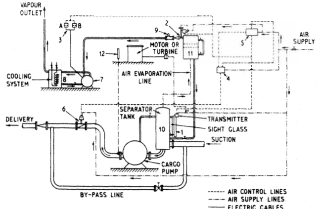
Step-by-Step Operational Sequence
The Vac-Strip system monitors the suction line dynamically and responds in three distinct stages:
1. Bulk Pumping (Full Head)
Oil flows freely from the tank through the large separator vessel (10) directly into the pump suction. The vessel is completely full of liquid; the Leveltrol displacer is fully immersed, holding the exhaust valve (2) shut and vacuum pump (7) stopped. The discharge butterfly valve (6) remains 100% open.
2. Onset of Snoring (Venting)
As the tank empties, air vortices enter the suction line and collect in separator tank (10). Liquid level drops. The Leveltrol displacer senses the falling level, increasing its pneumatic output signal to open exhaust valve (2) and start the liquid-ring vacuum pump (7), actively drawing entrained gases out of the oil before they reach the impeller eye.
3. Automatic Throttling
If gas ingress exceeds vacuum extraction capacity, liquid level in separator (10) falls further. The Leveltrol signal routes through high-selector relay (5) to modulate discharge butterfly valve (6) toward closed. Throttling increases back-pressure, perfectly matching pump discharge rate to the slow gravity inflow across the tank bottom without losing prime.
Once the tank bottom is completely drained, the butterfly valve closes fully, and the vacuum pump pulls the final residue out of the suction line, leaving the tank thoroughly stripped dry.
7. Reciprocating Stripping Pumps & Cargo Hold Eductors
Even with automated systems, tankers carry dedicated stripping hardware for line draining, crude oil washing (COW) supply, and final tank drying:
1. Reciprocating Duplex Stripping Pumps
Heavy vertical steam pumps with cast iron liquid ends and bronze-trimmed valves. Driven by direct boiler steam (typically 10 to 16 bar), these pumps can handle aerated sludges, high-viscosity waxy residues, and pure vapor without de-priming.
- Air Vessels: Fitted on the discharge manifold to absorb the violent pressure pulsations caused by piston reversal, preventing pipe joint fatigue.
- Self-Priming Ability: Capable of pulling a vacuum up to 650 mm Hg (0.85 bar), lifting oil residues from deep suction sumps.
2. Liquid Jet Eductors
A water or oil-driven jet eductor contains zero moving parts, making it completely immune to mechanical wear, cavitation erosion, or dry-running damage.
Convergent Driving Nozzle
High-pressure driving fluid (cargo oil or seawater at 8 to 10 bar from a main pump discharge) enters a converging nozzle, converting static pressure into a high-velocity jet (>30 m/s).
Mixing Chamber Suction
The high-speed jet creates a localized low-pressure vacuum zone around the nozzle tip, entraining air, gas, and oil residue from the tank suction line.
Divergent Diffuser
The combined stream passes through a tapered diffuser, converting kinetic velocity back into sufficient static discharge pressure to push the mixture into the slop tank.
8. Pumproom Safety, Atmospheric Monitoring & Trips
Danger: The Deadliest Enclosed Space Onboard
The cargo pumproom contains thousands of flanged joints, high-pressure pump casings, relief valves, and strainers handling flammable, volatile hydrocarbons. Heavy hydrocarbon vapors (such as butane and propane) and deadly Hydrogen Sulphide (H2S) are heavier than air and settle in the lowest bilges below floor plates.
SOLAS Regulation II-2/4.5.10 mandates strict architectural safeguards for tanker pumprooms:
- Continuous Mechanical Extraction Ventilation: Exhaust fans must provide at least 20 air changes per hour based on gross pumproom volume. Air must be extracted through vertical trunking drawing directly from the lowest bilges beneath the bottom floor plates. Fans must be spark-proof with non-metallic bronze impellers.
- Gas Detection Sampling Lines: Continuous hydrocarbon gas detection sampling points are positioned in exhaust ducting, directly above bottom bilges, at pump glands, and near bulkhead shaft seals. Sequential sampling cycles must test every point at least once every 30 minutes, sounding alarms at **10% Lower Explosive Limit (LEL)**.
- Emergency Shutdown (ESD) System: Remote pneumatic and electrical pull handles located outside the pumproom entrance and in the Cargo Control Room (CCR) trip all cargo pump steam stop valves, vent boiler steam lines, and shut fuel valves instantaneously in an emergency.
- Bilge Level High Alarms: Two independent explosion-proof float switches in the pumproom bilge warn of pipe rupture or casing failure long before liquid can reach hot pump bearings.
9. Surveyor Examination & Overhaul Clearances
During scheduled drydocking and Class Special Surveys, cargo pumps and their transmission systems are opened up for rigorous inspection:
| Component & Inspection Item | Standard Clearances & Tolerances | Surveyor Failure Criteria & Rectification |
|---|---|---|
| Impeller Casing Wear Rings | Diametrical clearance: 0.30 to 0.50 mm (typically renewed when exceeding 0.80 mm or 2× original). | Excessive wear allows high-pressure discharge liquid to short-circuit back to suction, destroying pump capacity and causing severe cavitation. |
| Vertical Shaft Runout | Total Indicator Reading (TIR) along shaft length measured with dial gauge: <0.05 mm. | Bent shaft induces high-frequency vibration, destroying mechanical seal faces and wiping white metal bearings within hours. |
| Mechanical Face Seals | Silicon carbide / tungsten carbide seal faces checked with optical monochromatic light flat (flatness within 2 light bands / 0.6 µm). | Scratched, chipped, or heat-crazed faces allow dangerous volatile crude oil to spray into the pumproom atmosphere. |
| Bulkhead Shaft Gland | Inspect carbon segmented rings and garter springs; pressure-test lubrication reservoir to 0.5 bar. | Defective gas seal allows explosive hydrocarbon vapors from pumproom to migrate directly into the engine room. |
| Turbine Overspeed Trip Test | Simulated mechanical trip test and physical overspeed run test to verify trip at exactly 110% to 115% rated RPM. | Mandatory Class surveyor safety check. Failure to trip requires complete disassembly, spring replacement, and re-certification. |
Standards & sources referenced
- SOLAS: International standards for the safety of life at sea.
- Conventions index
Found a mistake, or something unclear?
Report it in a few seconds — it goes straight to the editors.