

Submerged Hydraulic Cargo Pumps (Framo), Cofferdam Purging & Crude Oil Washing (COW)
Master Framo submerged hydraulic cargo pumps: concentric pipe cofferdam purging, stripping cycle, seal diagnostics, portable emergency pumps, deepwell pumps, and Crude Oil Washing (COW) for MEO Class 4 & 2 examinations.
1. Operational Philosophy & Pumproom Elimination
Warning: The Paradigm Shift in Tanker Design
Traditional tankers rely on a centralized pumproom situated at the bottom of the ship, forward of the engine room bulkhead. While effective for single-grade crude carriers, pumprooms pose catastrophic safety and commercial hazards on modern chemical and product carriers: gland leakage of carcinogenic, toxic, and highly flammable chemical vapors, massive suction pipe friction head loss, vulnerability to flooding, and irreversible contamination across multi-grade parcel cargoes.
In response to these risks, Scandinavian naval architects pioneered the submerged cargo pump system (most notably developed by Frank Mohn AS / Framo and Svanehøj). Instead of bringing cargo through thousands of meters of complex bottom suction piping to a shared pumproom, every individual cargo tank is equipped with its own dedicated, submerged centrifugal pump located at the lowest point of the tank floor in a recessed suction well.
Complete Pumproom Elimination
Eliminating bottom pumprooms removes the single most dangerous enclosed space on tankers. Cargo leaks cannot accumulate in confined engine-adjacent bilges, and hazardous pump gland overhauls inside explosive atmospheres are eradicated.
Infinite Parcel Segregation
Chemical tankers routinely transport 20 to 50 completely distinct chemical parcels simultaneously (e.g. toluene, phenol, caustic soda, phosphoric acid, and edible vegetable oils). Dedicated submerged pumps and separate deck drop lines ensure zero possibility of cross-contamination.
Elimination of Suction Lift Losses
Because the pump impeller is fully submerged in the cargo at the tank bottom, the available Net Positive Suction Head (NPSHA) is maximized by the liquid static head. There are no suction lines, friction losses, or air ingress points on the inlet side.
Integrated Stripping & Cleaning
The submerged unit acts as both the main discharge pump and the final stripping pump. A built-in discharge riser pipe and purging connection allow complete evacuation of the pump column and suction well down to negligible residues.
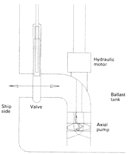
The submerged pump philosophy has also been adopted for segregated ballast tanks (SBT). Rather than running massive ballast lines through cargo zones, submerged ballast pumps installed inside double-bottom or wing ballast tanks provide direct, isolated ballast transfer with zero risk of cargo hydrocarbons migrating into clean ballast water.
2. Mechanical Architecture & The Concentric Pipe Design
The heart of the Frank Mohn (Framo) submerged cargo pump is a vertical assembly suspended from the tank top deck flange down to the bottom suction well. Because the pump is surrounded by corrosive, toxic, or flammable cargo, the mechanical drive and fluid pathways must provide absolute separation between the hydraulic driving oil, the surrounding cargo, and the external atmosphere.
This is accomplished through a masterpiece of precision marine engineering: the Triple Concentric Pipe System.
Component Deep-Dive
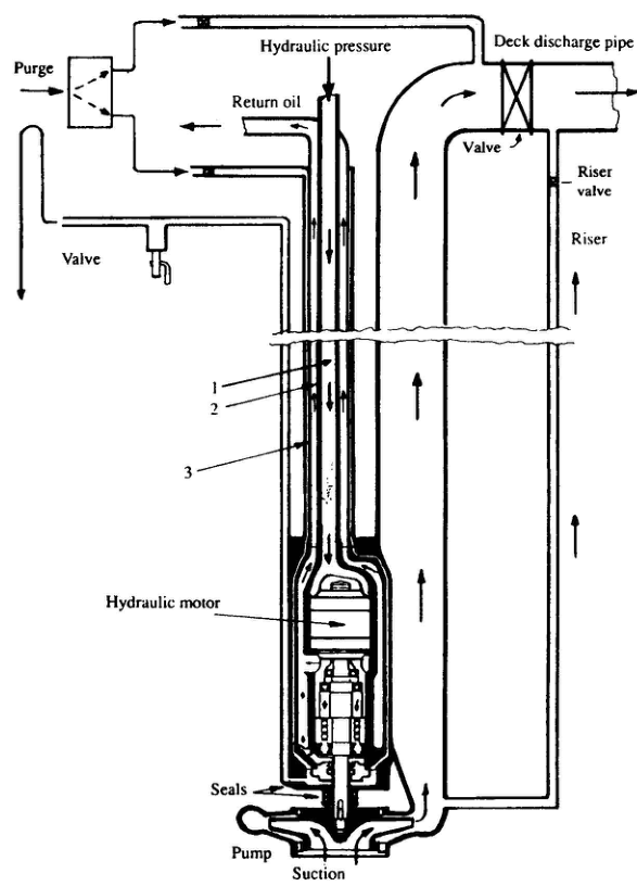
- Central High-Pressure Supply Pipe (Pipe 1): Delivers clean hydraulic oil at pressures up to 200–260 bar directly from the ship’s central hydraulic power pack into the motor inlet port.
- Intermediate Low-Pressure Return Pipe (Pipe 2): Surrounds Pipe 1 concentrically, carrying exhausted hydraulic oil back to the deck collector manifold at 3–5 bar backpressure. This annular design provides structural damping and thermal moderation.
- Outer Protective Cofferdam Pipe (Pipe 3): Encircles both hydraulic pipes, creating an air/gas-filled atmospheric barrier that completely separates the high-pressure hydraulic circuit from the surrounding cargo liquid in the tank. If an internal hydraulic leak occurs, oil escapes into the cofferdam—not into the cargo. Conversely, if cargo breaches the outer tube, it is trapped inside the cofferdam without entering the ship’s hydraulic machinery.
- Hydraulic Motor: A high-power-density, fixed-displacement bent-axis or radial piston motor situated inside the stainless steel casing directly above the pump impeller. Driven entirely by fluid flow, it requires zero electrical connections inside the explosive tank space.
- Archimedean Axial Inducer: Bolted to the drive shaft directly below the centrifugal impeller eye. The inducer consists of a low-pitch helical screw that generates a slight positive pressure rise at very low fluid velocities, drastically reducing the NPSH required (NPSHR) of the pump. This prevents cavitation when pumping volatile chemicals (like methanol or acetone) down to the last few centimeters of tank ullage.
- Pump Materials: All submerged parts, piping, casings, and impellers are fabricated from AISI 316L stainless steel or premium 254 SMO (super austenitic) / Duplex stainless steels (UNS S31803) to ensure complete passivation and resistance against pitting, crevice corrosion, and chemical attack by concentrated inorganic acids and corrosive cargo parcels.
3. The Cofferdam System, Dual Mechanical Seals & Purging Diagnostics
Danger: The Critical Barrier: Why the Cofferdam Must Be Monitored
The cofferdam is an enclosed atmospheric void surrounding the hydraulic lines and separating the hydraulic motor from the cargo pump casing. A failure of both seals simultaneously would allow hydraulic oil to contaminate valuable cargo, or toxic, flammable cargo to enter the ship's closed hydraulic ring main. Routine purging is the only method to detect a primary seal failure before secondary containment is compromised.
Dual Seal Hierarchy
The pump drive shaft passes through a dual-barrier sealing chamber:
- Upper Hydraulic Shaft Seal: Located immediately beneath the hydraulic motor. It seals against low-pressure return hydraulic oil (3–5 bar). If this seal wears, hydraulic oil drips into the cofferdam drain chamber.
- Lower Cargo Mechanical Seal: Mounted above the impeller hub. It consists of stationary and rotating silicon carbide (SiC vs SiC) or tungsten carbide faces energized by Hastelloy springs. Crucially, this seal is exposed only to the static liquid head of cargo in the tank—it is shielded from pump discharge pressure. If it degrades, cargo enters the cofferdam chamber.
- Intermediate Cofferdam Drain Chamber: The atmospheric space between the two seals. A small drain pipe runs from this chamber all the way up to a diagnostic exhaust valve and catchpot on the deck flange.
Step-by-Step Cofferdam Purging Diagnostic Routine ("The Purge Test")
Regulations and operating manuals mandate purging the cofferdam:
- Prior to loading: To verify that seals are dry and undamaged while the tank is empty.
- During voyage / before discharge: To verify no cargo has leaked across the lower seal during the loaded passage.
- Immediately after discharge: Before the cargo pump is stopped and isolated.
- Monthly at sea: Recorded in the vessel's official Cofferdam Purge Logbook.
| Discharge from Exhaust Trap | Underlying Defect | Engineering Evaluation & Permissible Thresholds |
|---|---|---|
| Dry Gas Only | Normal healthy operation | Seals intact. Both cofferdam volume and drainage chamber are clean. Record result in logbook. |
| Clean Hydraulic Oil | Upper hydraulic motor shaft seal worn or damaged | Normal seepage limit is < 1.0 litre/hour (or < 0.5 l/h for smaller units). If leakage exceeds this threshold, the motor seal must be renewed before the next loading to avoid hydraulic oil starvation. |
| Cargo Liquid / Odor | Lower mechanical cargo seal face cracked, hung up, or eroded | Strict limit: < 0.5 litre/hour for non-toxic cargoes; 0 tolerance for highly toxic/reactive chemicals (IBC Code Class 1 & 2). Continued operation allows cargo to corrode internal motor casing. |
| Clear Fresh Water | Atmospheric condensation | Normal tropical humidity sweating. If water volume is high (> 2 litres), check purge air dryer performance or test for saltwater ingress. |
| Milky Emulsion (Oil + Water/Cargo) | Dual seal degradation or cofferdam contamination | Immediate pump shutdown. Danger of cross-contamination into hydraulic power pack. Pump must be isolated hydraulically and stripped. |
4. Hydraulic Power Transmission & Proportional Speed Control
Submerged cargo pumps require enormous torque and variable operational speeds, ranging from gentle idling during priming (150–200 RPM) to maximum discharge delivery (up to 2,000–2,500 RPM). Rather than running high-voltage electricity onto the hazardous cargo deck, power is supplied by a centralized closed-loop electro-hydraulic power pack located in a dedicated hydraulic room inside the machinery space.
The Central Hydraulic Power Pack
The power station consists of multiple prime movers connected in parallel:
- Main Electric-Driven Pump Sets: Typically 3 to 6 high-pressure variable-displacement swashplate axial piston pumps (e.g. Rexroth or Parker Hannifin) driven by constant-speed 440V / 6.6kV electric motors.
- Diesel-Driven Emergency / Peak Pump Sets: Dedicated auxiliary diesel engines clutched directly to hydraulic swashplate pumps, providing full discharge capability during blackouts or shore electrical load shedding.
- Reservoir & Conditioning Module: A large hydraulic tank maintained with an expansive oil volume (5,000 to 15,000 litres of ISO VG 46/68 mineral hydraulic oil), an inert nitrogen blanket to prevent oxidation and moisture absorption, dual water-cooled plate heat exchangers, and immersion heating coils to maintain optimal operating temperature between 45°C and 55°C.
- High-Pressure Filtration: Continuous 3-micron absolute pressure and return filters equipped with differential pressure (ΔP) electrical transmitters to ensure fluid cleanliness conforming to ISO 4406 Class 15/13.
Constant-Pressure Ring Main Control
The power pack operates on a constant-pressure ring main philosophy. The variable displacement pumps adjust their swashplate angles via internal hydraulic electro-proportional servo controls to maintain a rock-steady ring main pressure of 200 to 260 bar, regardless of whether 1 pump or 16 pumps are operating simultaneously. When cargo valves are opened, system pressure dips fractionally; the swashplates immediately stroke to full angle, delivering up to thousands of litres per minute of hydraulic flow on demand.
Speed Torque Controller (STC)
Each cargo pump has an integrated Framo STC valve on deck. The STC regulates hydraulic oil flow into the submerged motor, maintaining precise impeller speed regardless of changing cargo specific gravity, viscosity, or shore discharge manifold backpressure.
Hydraulic Soft Start
Direct electric pumps produce massive current spikes and pipeline pressure shocks. The hydraulic STC valve initiates a gradual ramp-up (soft start over 15–30 seconds), preventing hydraulic oil hammer, discharge pipe surge, and shore line pressure spikes.
Stepless Proportional Control
Cargo pump discharge rate is controlled with millimeter precision from the Cargo Control Room (CCR) touchscreens. Operators adjust flow rate without throttling cargo discharge butterfly valves, eliminating valve seat erosion.
High-Pressure Safety Relief
Every individual pump circuit contains a pilot-operated high-pressure relief valve set to 280 bar. If an operator inadvertently deadheads a pump against a closed deck manifold, oil recirculates safely to the return line without stalling the motor.
5. Stripping Cycle, Tank Drainage & Discharge Pipe Clearing
Warning: MARPOL Annex II Stripping Compliance
Under MARPOL Annex II (Regulation 12), chemical tankers constructed on or after 1 January 2007 must strip each cargo tank such that the remaining residue on tank bulkheads, bottom framing, pump casings, and piping does not exceed 75 litres (and under 50 litres for IBC Code Category X, Y, and Z substances). Conventional suction piping cannot achieve this without expensive manual squeegeeing. Submerged pumps achieve compliance through automated purging stripping.
In a submerged pump installation, the vertical discharge pipe (typically 150 to 300 mm diameter and 15 to 25 meters long) contains several tonnes of cargo when pumping ceases. If the pump is simply shut down, this entire column of liquid drains straight back down through the impeller into the tank, completely refilling the suction well and violating international pollution regulations.
The Framo Discharge Pipe Stripping Sequence
The stripping and clearing routine utilizes high-pressure compressed air or inert gas (nitrogen) at 7 bar to evacuate both the suction well and the discharge pipe without requiring a separate reciprocating stripping pump.
| Step | Operational Action | Internal Physical Mechanism |
|---|---|---|
| Step 1: Pumping Down | Cargo level approaches tank bottom framing (approx. 0.5 m ullage). | Reduce hydraulic motor speed via CCR to approximately 40–50% rated RPM. This prevents vortex formation, air snoring, and cavitation at the suction bellmouth while maintaining a stable liquid ring. |
| Step 2: Well Clearing | Liquid level drops into the recessed suction well. | The Archimedean inducer sweeps the well bottom. Throttle pump speed down to minimum idling RPM (approx. 150–200 RPM). |
| Step 3: Discharge Valve Closure | Pump suction loses head; discharge pressure begins to flutter. | Leave the submerged pump idling to act as a dynamic non-return barrier preventing cargo backflow. Immediately close the main deck cargo discharge valve. |
| Step 4: Gas Injection (Purging) | Connect compressed air or nitrogen (N2) supply to the deck discharge pipe purge connection. | Open the purge valve (7.0 bar). The pressurized gas enters the top of the vertical discharge pipe, exerting downward pressure on the liquid column while the idling pump continues creating an upward velocity seal at the bottom. |
| Step 5: Liquid Evacuation | Gas pressure drives the trapped column upwards through the internal small riser pipe. | Because the main deck valve is shut, the liquid is forced up through the internal small-bore riser pipe (30–50 mm diameter) directly into the deck cargo main line ashore. |
| Step 6: Gas Blow-Through & Trip | Discharge pressure gauge suddenly drops to zero or registers fluctuating gas blow-through. | The pipe and suction well are completely dry. Close the purging gas valve. Trip the hydraulic motor to 0 RPM. Close the riser valve and deck manifold isolation valve. |
By executing this sequence, the remaining cargo residue inside the tank well and pipe column is reduced to under 20 to 50 litres, easily passing strict Port State Control (PSC) and vetting inspections without requiring crew entry into toxic atmospheres.
6. Portable Submersible Emergency Cargo Pumps
Danger: The Single-Point Failure Vulnerability & Regulatory Mandate
Because submerged pump systems do not have cross-over bottom suction headers connecting adjacent tanks, a catastrophic mechanical or hydraulic failure of a submerged pump in a loaded tank would trap hundreds or thousands of tonnes of cargo indefinitely. SOLAS, the IBC Code, and classification society rules mandate that chemical and product tankers carry at least one portable hydraulically driven submersible emergency cargo pump capable of recovering cargo from any loaded tank.
Emergency Pump Construction & Capabilities
The portable emergency pump (e.g. Framo TK-series, such as the TK-80 or TK-150) is a compact, ultra-lightweight unit constructed entirely from acid-resistant stainless steel (AISI 316L). Capable of passing through a standard 12-inch (300 mm) Butterworth tank cleaning hatch, it delivers high discharge rates (typically 70 to 300 m³/h at 70–100 m head).
Concentric Flexible Hose Bundle
Power and discharge are supplied through a flexible composite hose bundle: high-pressure hydraulic supply, return hose, cofferdam leak-detection sniffer line, and a reinforced 6-inch flexible cargo discharge hose.
Quick-Connect Couplings
Hydraulic connections utilize flat-faced, non-drip, quick-release dry-break couplings that prevent hydraulic oil loss or air ingress when mating to the deck hydraulic ring main outlets.
Air/Tripod Rigging Winch
The pump weighs approximately 40 to 120 kg. It is lowered into the tank suspended from a non-sparking stainless steel wire rope attached to a portable deck tripod and pneumatic hoist.
Static Grounding Bonding Cable
Pumping static charges can ignite flammable ullage spaces. Heavy-duty copper bonding clamps must bridge the pump casing to the ship’s hull plating prior to opening the Butterworth hatch.
Standard Deployment Protocol
- Safety Assessment & Tank Inerting: Confirm tank atmosphere is maintained under positive pressure with inert gas oxygen content < 8% by volume. If cargo is flammable, do not vent to atmosphere.
- Grounding & Bonding: Connect the heavy-duty grounding cable from the portable pump frame to bare metal on the deck coaming. Measure continuity using an intrinsically safe ohmmeter (resistance must be < 10 ohms).
- Hatch Opening & Rigging: Open the designated Butterworth hatch. Erect the aluminum/stainless steel tripod and secure the pneumatic winch. Rig the pump over the center of the opening.
- Hydraulic Connection: Connect the hydraulic supply and return hoses to the nearest deck emergency hydraulic service station. Crack the deck service valve to verify oil circulation and check cofferdam sniffer for dry operation.
- Controlled Lowering: Lower the pump slowly through the vapor space. Avoid swinging or striking internal tank bulkheads, ladders, or heating coils. Lower until the pump suction bellmouth sits firmly on the bottom of the tank well.
- Cargo Discharge Connection: Connect the flexible cargo discharge hose to the dedicated portable pump connection on the deck cargo manifold.
- Pumping Operation: Slowly open the hydraulic control valve to initiate soft start. Maintain steady pumping until the tank is stripped dry.
7. Deepwell Pumps for Liquefied Gas Carriers (LPG / LNG / Ammonia)
While hydraulically driven submerged pumps dominate chemical and oil product tankers, they cannot be used for cryogenic liquefied gas cargoes (e.g. Liquefied Petroleum Gas at -48°C, Liquefied Natural Gas at -162°C, or anhydrous Ammonia at -33°C). At these extreme sub-zero temperatures, standard hydraulic oils freeze solid or experience exponential viscosity increases far below their pour points.
Liquefied gas carriers solve this challenge through two distinct engineering architectures: Vertical Line-Shaft Deepwell Pumps and Submerged Electric Canned-Motor Pumps.
Architecture of the Vertical Line-Shaft Deepwell Pump (Svanehøj Type)
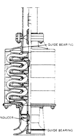
A multi-stage centrifugal pump assembly rests at the tank bottom, driven by an electric motor or steam turbine located on the weather deck outside the hazardous tank environment:
- Deck-Mounted Drive Head: An explosion-proof (Ex-d / Ex-p) electric motor is mounted on the open deck, driving the line shaft via a flexible coupling and heavy-duty thrust bearing that absorbs both upward hydraulic lift and downward shaft assembly weight.
- Deck Gas-Tight Sealing: The drive shaft passes into the tank through a double mechanical face seal pressurized with an external lubricating oil barrier. This ensures cryogenic cargo boil-off vapor cannot escape onto the deck.
- Multi-Section Line Shaft & Bearings: A precision-machined vertical shaft (often 15 to 30 meters long) connects the deck motor to the bottom impeller stages. The shaft is housed inside the cargo discharge pipe and supported every 2 to 3 meters by carbon or PTFE guide bearings.
- Product-Lubricated Bearings: The shaft bearings are continuously lubricated and cooled by the liquefied gas cargo itself as it flows up the discharge pipe. Running a deepwell pump dry will destroy carbon sleeve bearings within minutes, necessitating low-flow thermal trips and minimum pressure cut-outs.
- Multi-Stage Impeller Stack: Because liquefied gas has low density and high vapor pressure, discharge head is developed through 2 to 6 centrifugal stages in series, fitted with an Archimedean inducer at the suction eye.
Submerged Electric "Canned-Motor" Pumps (LNG Carriers)
For large LNG carriers (-162°C), vertical line shafts of 30-meter length introduce severe thermal contraction and alignment problems. These vessels utilize submerged canned electric motor pumps (e.g. Shinko or Ebara) installed in pump towers:
- The electric motor and centrifugal pump share a common shaft inside a hermetically sealed aluminum or stainless steel casing resting at the tank bottom.
- The motor windings are completely submerged in and cooled by boiling liquid methane. Because the tank atmosphere consists of 100% pure methane with zero oxygen present, electrical sparking cannot ignite the liquid or vapor.
- Special cryogenic insulation (Class H polyimide / quartz materials) and ceramic ball bearings lubricated entirely by liquid LNG withstand indefinite sub-zero operation.
8. Crude Oil Washing (COW) Systems & Operational Protocols
Warning: The Chemistry & Economics of Crude Oil Washing
Crude oil is not a simple liquid; it is a complex hydrocarbon mixture containing heavy paraffin waxes, asphaltenes, sediment, and heavy bituminous residues. During loaded voyages, these heavy fractions settle onto horizontal structural surfaces—bottom longitudinals, deck beams, stringers, and frames—forming a dense, sticky sludge up to 0.5 meters thick. Water washing fails because oil and water do not mix; Crude Oil Washing (COW) uses warm crude cargo as a natural solvent to dissolve and recover this sludge, pumping it ashore as valuable commercial product.
Regulatory Framework: MARPOL Annex I & Resolution A.446(XI)
MARPOL Annex I mandates that every crude oil tanker of 20,000 tonnes DWT and above delivered after 1 June 1982 must be fitted with an approved, fully dedicated Crude Oil Washing installation and an approved COW Operations and Equipment Manual.
Strict Inert Gas (IGS) Requirement
Crude oil jets striking steel bulkheads create massive electrostatic charges. COW is strictly prohibited unless the tank atmosphere oxygen level is verified below 8% by volume (most companies enforce < 5%) with positive pressure maintained throughout the wash.
Wash Oil Temperature Control
Washing crude must be warm to ensure high solvent capability. The oil must be heated to at least 5°C above its pour point (typically 40°C to 55°C) using cargo steam heating coils prior to circulation.
Fixed Washing Machines Only
Only permanently attached, deck-mounted or submerged programmable jet cleaning machines (e.g. Butterworth, Victor Pyrate) may be used. Portable water washing hoses are strictly banned for crude washing.
Mandatory Tanker Logbook Entries
Every COW operation must be recorded in the Oil Record Book (Part II), documenting date, tank numbers, machine running hours, wash oil source, and final stripping verification.
Operational Washing Phases: Top Wash vs. Bottom Wash
A complete tank Crude Oil Wash is divided into distinct phases executed concurrently with the commercial discharge:
- Top Washing Phase (Upper Tank Cleaning):
- Timing: Initiated when cargo discharge has emptied approximately one-third to one-half of the tank ullage, exposing the upper bulkheads and overhead longitudinal deck frames.
- Machine Angle: The programmable nozzle sweeps through a high elevation arc (typically from 150° down to 90° or 60° relative to vertical).
- Purpose: Washes clinging oil residues off deck longitudinals and upper plating before the crude dries or bakes onto steel exposed to warm weather.
- Bottom Washing Phase (Floor & Structural Frame Scrubbing):
- Timing: Executed when the tank is virtually empty (with only 1 to 2 meters of cargo remaining above the bottom floor) or during final well drainage.
- Machine Angle: The machine is set to a low, concentrated downward arc (from 40° down to 0° horizontal sweep).
- Intensive Scouring: High-pressure oil jets (8 to 10 bar) blast directly into the bottom longitudinal channels, bracket corners, and limber holes, dislodging compacted wax banks and sweeping residues directly toward the pump suction well.
- Crucial Stripping Rule ("Dry Bottom"): The cargo stripping system must operate continuously during the bottom wash. If the stripping pump or eductor fails to keep up, wash oil will pool on the bottom, dampening and absorbing the mechanical impact energy of the jet nozzles. Tank floor draining is continuously verified using electronic dipping tapes or ullage level sensors.
COW Quality & Safety Checklist for MEO Oral Exams
- Inert Gas Verification: Oxygen analyzer calibrated; tank pressure positive (minimum 200 mm water gauge); O2 confirmed < 5%.
- Line Pressure: COW supply line pressure verified between 8.0 and 10.0 bar to ensure adequate jet reach (up to 30–35 meters).
- Machine Movement Indicator: Ensure external mechanical drive stems/indicators on deck are visibly rotating; a stalled nozzle will fail to wash the tank and could cut structural coatings.
- Deballasting Regulations: If a cargo tank is slated to receive heavy-weather emergency ballast water at sea, that tank must undergo a full crude oil wash followed by a thorough hot-water rinse before departure.
Standards & sources referenced
- SOLAS: International standards for the safety of life at sea.
- MARPOL: International rules to prevent pollution from ships.
- Conventions index
Found a mistake, or something unclear?
Report it in a few seconds — it goes straight to the editors.