

Positive Displacement Pumps (Screw, Gear, Reciprocating) & Jet Eductors
Master marine positive displacement pumps: triple-screw IMO pumps, external gear pumps, Mono cavity pumps, reciprocating pumps, and jet eductors for MEO Class 4 & 2 examinations.
1. Volumetric Displacement Philosophy vs. Centrifugal Pumps
Danger: The Cardinal Operating Rule of Positive Displacement
NEVER start or run a positive displacement pump against a closed discharge valve. While a centrifugal pump simply churns liquid inside its casing at shut-off head, a positive displacement pump continues delivering a fixed volume of incompressible fluid with every revolution. Pressure escalates instantly until the pipe ruptures, the pump casing splits, or the electric motor trips on massive overload.
In marine auxiliary systems, pumps are divided into two fundamental hydrodynamic classes: Rotodynamic (Centrifugal) and Positive Displacement (PD). Understanding their operational differences is vital for shipboard safety and system design.
Rotodynamic (Centrifugal)
Imparts kinetic velocity energy to fluid via an impeller, converting dynamic head to static pressure in a volute. Flow rate varies drastically with system backpressure; cannot pump air and requires external priming.
Positive Displacement (PD)
Traps a discrete volume of fluid inside expanding cavities on the suction side, seals it, and positively displaces it into the discharge main. Flow rate remains nearly constant regardless of discharge pressure.
Inherent Self-Priming
Because running clearances between rotors and casings are extremely small (0.03 to 0.08 mm), PD pumps act as dry vacuum pumps, pulling air and vapor from dry suction lines without auxiliary primers.
Mandatory Relief Valve
Every PD pump must be protected by an integral or dedicated external spring-loaded safety relief valve discharging back to the suction side, standardly set at 10% above maximum working pressure.
Theoretical vs. Actual Flow (The Physics of Slip)
The theoretical displacement capacity of a rotary PD pump is strictly a function of displaced volume per revolution (Vd) and rotational speed (N):
Qtheoretical = Vd × N
In real marine pumps, internal clearances allow a small fraction of high-pressure discharge liquid to leak back to the low-pressure suction side. This internal back-leakage is termed Slip (Qslip):
Qactual = Qtheoretical − Qslip
Qslip ∝ ΔP × c³μ
where ΔP is differential pressure across the pump, c is internal radial clearance, and μ is fluid dynamic viscosity. Crucially, slip is independent of running speed but increases with the cube of clearance wear! If radial clearance doubles due to abrasive wear, slip increases by a factor of eight (2³ = 8), severely degrading pump delivery at high pressures.
2. Three-Screw (IMO) Displacement Pumps
The three-screw displacement pump (universally known across world shipping as the IMO pump, invented by Carl Montelius) is the primary choice for main engine lubricating oil, stern tube circulation, fuel oil booster modules, and hydraulic power units.
Working Principle & Component Details
- The Power Rotor & Idlers: Only the central power rotor is coupled to the electric drive motor. It features convex (male) profile threads. The two outer idler rotors have concave (female) profiles. The idlers are not driven by timing gears; they are rotated purely by the hydrodynamic film created by the pumped liquid. They act entirely as dynamic fluid seals, separating the suction chamber from the discharge chamber.
- Endless Axial Piston Action: As the intermeshing screws rotate, their tight clearances form sealed cavities within the screw helices. These cavities move continuously in an axial direction from suction to discharge. The liquid does not rotate; it is gently and steadily translated forward exactly like a continuous solid liquid piston moving through a cylinder. This produces completely pulse-free, silent flow without vibration.
- Axial Hydraulic Thrust Balancing: Because high discharge pressure acts against the discharge ends of the screws, a tremendous axial thrust pushes the power rotor back toward the motor coupling. To balance this force without requiring massive mechanical thrust bearings:
- A hydraulic balance piston is machined onto the power rotor shaft immediately adjacent to the mechanical seal. High-pressure discharge oil is routed to one side of the piston, while the other side vents to suction pressure, generating an equal and opposite forward counter-thrust.
- Alternatively, on large cargo pumps, a double-ended counterscrew design is used: screws have both left-hand and right-hand threads on the same shaft. Fluid enters at both outer ends and meets in the middle discharge port, cancelling out all axial forces hydraulically.
- Lubrication Dependency: Because the idler screws roll directly in the casing bore and against the power rotor, IMO pumps depend completely on the lubricating properties of the fluid being pumped. Pumping dry, or running on non-lubricating liquids (like seawater or light chemical solvents), causes instantaneous metal-to-metal galling and seizure.
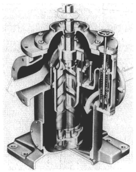
3. Two-Screw Pumps with External Timing Gears
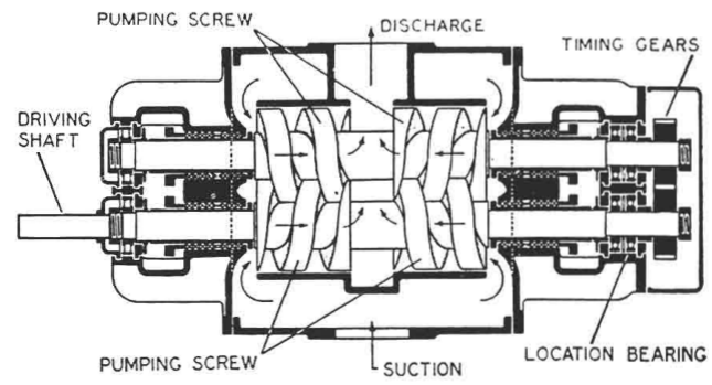
When the fluid being pumped has poor lubricity, contains abrasive particulates, or must be stripped dry from tank bottoms, the three-screw design cannot be used. Instead, marine systems utilize the Two-Screw Pump with External Timing Gears and Bearings (such as the Weir or Houttuin designs).
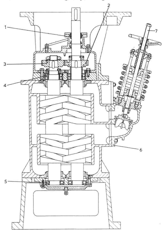
Key Mechanical Differences from Three-Screw Pumps
External Timing Gears
Hardened spur or helical timing gears synchronize the rotation of the two screw shafts with microscopic precision. The screw threads never touch each other; all torque transmission occurs through the gears in an external oil bath.
External Bearing Housings
Shaft support bearings are located outside the liquid pumping chamber, sealed behind mechanical shaft seals. The bearings are lubricated by clean grease or auxiliary oil, completely isolated from corrosive cargo.
Non-Lubricating Fluid Handling
Because there is zero metal-to-metal contact between internal rotors and casing bores, two-screw pumps can safely pump water, dirty ballast, molasses, light naphtha, and heavy fuel sludge without galling.
Dry Running & Stripping
Can run dry for extended periods during tank stripping cycles, pulling high vacuum to remove the final centimeters of liquid and vapor from cargo tanks.
4. External & Internal Gear Pumps
Gear pumps are widely employed for auxiliary diesel generator lube oil priming, boiler burner fuel delivery, separator feed, and deck crane hydraulic servos. They are simple, rugged, compact, and capable of generating discharge pressures up to 20 to 30 bar.
Hydrodynamic Principles & The Trapping Phenomenon
- Fluid Ingress at Suction: As the teeth unmesh on the suction side, the volume between adjacent gear teeth expands rapidly, creating a localized vacuum. Atmospheric or header tank pressure forces fluid into the expanding tooth pockets.
- Peripheral Transport: Liquid trapped in the spaces between the gear teeth and the close-fitting circular casing wall is carried around the outer circumference of the casing. Liquid does NOT flow straight through the center of the pump!
- Positive Displacement at Discharge: On the discharge side, the teeth of the driver and driven gears re-engage (mesh). The tooth of one gear penetrates the pocket of the mating gear, squeezing out the trapped fluid and forcing it into the discharge pipeline.
- The Trapping Relief Slots (Anti-Hydraulic Lock): As two teeth come into full mesh, a tiny pocket of liquid becomes completely sealed between the contact points of the driving and driven teeth before the mesh is complete. Because liquids are incompressible, continued tooth rotation into this closed pocket would generate instantaneous hydraulic pressures exceeding 300 to 500 bar, causing severe gear tooth bending, bearing overload, and deafening noise. To prevent this, precision anti-trapping relief slots are machined into the end wear plates or casing side walls, allowing the trapped liquid to escape freely into the discharge port.
5. Mono (Progressive Cavity) Pumps for Low-Shear OWS Feed
Warning: The 15 ppm Oily Water Separator (OWS) Mandate
Feeding a 15 ppm bilge separator with a high-speed centrifugal pump is disastrous: high-speed impeller shearing chops large oil droplets into microscopic particles (< 20 microns), forming a tight, mechanically stable oil-in-water emulsion that cannot be separated by gravity or coalescing filters. MARPOL Annex I compliance demands a low-shear, non-emulsifying positive displacement pump—the Mono (Progressive Cavity) Pump.
Progressive Cavity Architecture (Rene Moineau Principle)
The Mono pump consists of two primary elements engineered with different geometric profiles:
- The Rotor: A single-lead helical screw precision-machined from corrosion-resistant hardened stainless steel (AISI 316) or hard-chrome-plated tool steel. The rotor rotates eccentrically inside the pump.
- The Stator: A double-lead internal helical sleeve molded from a resilient elastomer (Nitrile rubber for oils, EPDM for chemicals, or Viton for high-temperature sludge).
- Universal Drive Shaft: Because the rotor orbits eccentrically as it spins, it is connected to the motor drive shaft through a flexible connecting rod fitted with double universal pin joints or flexible elastomeric bushes.
Pumping Action & Advantages
As the single-helix rotor turns inside the double-helix stator, a continuous series of sealed, crescent-shaped cavities forms at the suction end. These cavities progress smoothly and axially from suction to discharge without expanding or contracting in volume. The liquid is conveyed like an undisturbed plug of fluid: zero turbulence, zero pulsation, and near-zero fluid shear stress.
Zero Emulsification
Maintains large oil droplet sizes, allowing oily bilge water to separate immediately in gravity coalesce chambers, preventing false oil content monitor (OCM) alarms.
High Viscosity & Heavy Sludge
Handles thick separator waste sludge, centrifuge bottoms, sewage slurries, and liquids containing suspended sand, rust grit, and heavy particulates.
High Suction Lift Capability
Generates high vacuum up to -0.85 bar gauge, easily pulling heavy waste oils out of bottom double-bottom bilge wells located 6 to 8 meters below the pump floor.
Dry Running Sensitivity
Crucial Vulnerability: The rubber stator relies on the liquid being pumped for cooling and boundary lubrication. Running dry for even 30 to 60 seconds generates intense frictional heat that melts, scorches, and tears the rubber stator lining.
6. Reciprocating Duplex Pumps (Steam & Motor Driven)
Reciprocating pumps (such as the classic steam-driven Lamont, Weir, or Dawson & Downie duplex pumps) represent the oldest positive displacement technology in marine engineering. Despite being largely replaced by rotary units for general service, they remain unmatched for boiler emergency feed, cargo stripping, and heavy bilge clearing due to their immense suction pulling power and ability to pump boiling water near saturation.
Duplex Double-Acting Pumping Cycle
A duplex pump features two identical steam cylinders driving two adjacent liquid pumping cylinders. Each pump cylinder is double-acting, displacing liquid on both the forward and return strokes:
- Forward Stroke: The piston moves forward, compressing liquid in the front chamber and forcing discharge valve D1 open. Simultaneously, a vacuum is pulled in the rear chamber, drawing fresh liquid in through suction valve S2.
- Return Stroke: The piston reverses, forcing liquid out through discharge valve D2 while drawing fresh fluid in through suction valve S1.
- Duplex Phasing: The valve gear of one cylinder is mechanically cross-linked to the piston rod of the adjacent cylinder. When one piston reaches stroke end and pauses to reverse, the second piston is at maximum mid-stroke velocity. This staggered phasing ensures continuous, steady liquid delivery without dead spots.
The Air Vessel (Pulsation Dampener)
Because piston velocity varies sinusoidally throughout each stroke, reciprocating pumps produce severe pressure pulsations and flow fluctuations. To protect pipe joints and pressure gauges from dynamic shock, a cast iron or steel Air Vessel is mounted on the discharge manifold:
- During peak piston acceleration (mid-stroke), excess liquid enters the air vessel, compressing the trapped air cushion inside the dome.
- At stroke end, when piston speed slows to zero, the compressed air expands, forcing the stored water out into the discharge main.
- This pneumatic dampening converts an erratic pulsating stream into a smooth, steady continuous flow.
Displacement & Volumetric Efficiency Calculations
Displacement for a double-acting cylinder of diameter D, stroke length L, piston rod diameter d, and speed n (strokes per minute) is:
Vstroke = [ (π/4 · D²) + (π/4 · (D² − d²)) ] × L
Volumetric Efficiency: ηv = QactualQtheoretical × 100%
Typical volumetric efficiency for a well-maintained marine duplex pump is 90% to 95%. A drop below 85% indicates worn rubber/bronze valve discs, broken valve springs, or degraded piston leather/PTFE packing rings.
7. Jet Eductors (Venturi Ejector Pumps)
Warning: The Magic of Pumping with Zero Moving Parts
Jet eductors have no pistons, no impellers, no mechanical seals, and no electric motors. They cannot burn out, cannot seize, and can pass sand, rust flakes, gravel, fish, and heavy oil sludge without damage. They are the supreme tool for chain locker drainage, cargo tank final stripping, bow thruster room bilge salvage, and sewage vacuum generation.
Working Mechanism: Three Velocity-Pressure Stages
- Nozzle Acceleration Stage: Motive water (supplied from a centrifugal fire, ballast, or cargo pump at 6 to 9 bar gauge) enters the convergent driving nozzle. As cross-sectional area contracts, pressure energy converts into immense kinetic velocity energy: the motive stream emerges as a high-speed jet exceeding 30 to 40 m/s.
- Suction Entrainment & Mixing Stage: By Bernoulli’s equation, the skyrocketing jet velocity causes localized static pressure in the suction chamber to plunge into a deep vacuum (-0.8 to -0.9 bar gauge). This powerful suction draws in the external fluid (bilge water, muddy ballast, or cargo residue). The two streams enter the parallel mixing throat, where intense turbulent shear transfers momentum from the motive jet to the entrained fluid.
- Diffuser Pressure Recovery Stage: The combined stream enters the divergent diffuser cone. As the flow area gradually expands, fluid velocity decelerates smoothly, converting dynamic kinetic energy back into sufficient static pressure to overcome external overboard head or climb up to the deck slop tank (typically 1.5 to 2.5 bar backpressure).
Danger: The Critical Back-Flooding Hazard
If the motive water supply pressure drops below the critical minimum (e.g. fire pump trips or someone opens another fire hydrant), the eductor loses its suction vacuum instantaneously. High-pressure water from the discharge main or motive supply will reverse direction and flood directly down the suction line into the dry cargo hold or bilge well. Every marine eductor must have a spring-loaded non-return swing check valve on its suction branch, and operating protocol dictates: Always start motive water first, then open suction; when stopping, always shut suction first, then shut motive water.
8. Watchkeeping, Clearances & Troubleshooting Matrix
Maintaining positive displacement pumps requires vigilance regarding relief valve settings, seal conditions, and clearance wear.
| Symptom / Fault | Underlying Mechanical Cause | Diagnostic Test & Corrective Action |
|---|---|---|
| Rapid Discharge Pressure Drop under Load | Excessive radial clearance wear between screw/gear tips and casing liner (excessive slip) | Measure slip against oil temperature. When cold (viscous), pressure holds; when hot, pressure collapses. Disassemble and check radial clearance using feeler gauges (renew if > 0.15 mm). |
| Loud Chattering / High-Pitched Scream | Relief valve lifting continuously due to downstream restriction or broken spring | Feel relief valve bypass pipe: if piping is piping-hot, liquid is recirculating through the relief valve. Check downstream line valves; test and reset relief spring setting. |
| Severe Cavitation Knocking & Vibration | High suction vacuum due to clogged suction strainer or cold, excessively viscous oil | Check suction vacuum gauge. If vacuum exceeds -0.45 bar, stop pump immediately. Clean magnetic suction basket; activate tank steam heating coils to lower oil viscosity. |
| Mechanical Seal Overheating & Leakage | Dry running or internal balance piston port blocked | Verify suction line is primed before start. Clean internal balance piston drain drilling returning to suction side. |
| Mono Pump Motor Trips on Overload | Stator dry friction or excessive swelling of rubber stator in chemical cargo | Never start Mono pump dry; always fill casing with liquid through priming funnel. Verify stator elastomer compatibility with cargo (e.g. Nitrile for oil, Viton for aromatics). |
Surveyor Clearances & Inspection Standards
- Screw Pump Radial Clearances: Normal diametrical clearance between screw outside diameter and liner bore is 0.04 to 0.08 mm. The maximum allowable wear limit before volumetric efficiency collapses is 0.18 mm.
- Gear Pump Backlash & Side Clearances: Tooth backlash should be maintained at 0.10 to 0.15 mm. Side clearance between gear faces and wear plates is strictly 0.05 to 0.08 mm; excessive side clearance is the primary source of high-pressure slip.
- Relief Valve Survey Mandate: During Class Annual and Special Surveys, surveyors witness the physical lifting test of the pump relief valve. With the discharge valve throttled closed, the relief valve must open cleanly and circulate 100% full pump capacity without casing pressure exceeding 110% of maximum rated design pressure.
Standards & sources referenced
- MARPOL: International rules to prevent pollution from ships.
- Conventions index
Found a mistake, or something unclear?
Report it in a few seconds — it goes straight to the editors.
- Pump Principles and Pump Types
- Centrifugal Pump Construction
- Axial Thrust Balancing & Balance Holes in Centrifugal Pumps
- Suction, NPSH, Cavitation and Priming
- Pump Curves and Speed Rules Made Simple
- Operation and Watchkeeping
- Pumping Systems Onboard
- Troubleshooting Index
- Overhaul, Inspection and Repair
- Safety and Emergency Actions
- Positive Displacement Pumps (Screw, Gear, Reciprocating) & Jet Eductors