

Steam and Condensate System — Interactive One-Line Diagram
Interactive steam and condensate system P&ID for a motor ship: auxiliary oil-fired boiler, exhaust gas boiler, main stop valve, pressure reducing valve, fuel oil and purifier heaters, the intermediate heating water heater, steam traps, cascade and observation tank, feed pumps, feed stop and feed check valves, and the surplus steam dump valve.
1. Interactive P&ID Line Diagram
The complete steam and condensate system of a motor ship, drawn the same way as the other line diagrams on this site. The heat source is on the left — the exhaust gas boiler in the main engine exhaust above, the oil-fired auxiliary boiler below, sharing one steam and water circuit through the forced circulation pump. Steam leaves the top of the boiler through the main stop valve, drops to heating pressure across the pressure reducing valve, and runs along the top of the drawing to the distribution header. Six consumers hang off that header, each with its own steam trap on the outlet. The condensate returns along the bottom, through the oil trap, into the cascade and observation tank, and is pumped back to the boiler past the feed stop and feed check valves.
Hover over any symbol to inspect its operation, duty and failure symptoms, and use the mouse wheel or the toolbar buttons to zoom and pan across the layout.
Reference: Ship's Piping Diagram
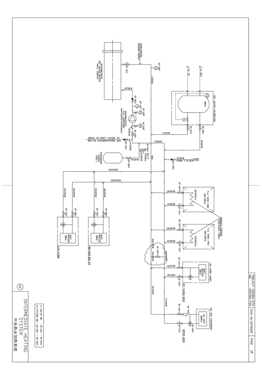
Alongside the interactive diagram above, here is the intermediate heating water system as drawn by the shipyard in an engine-room piping diagram booklet. It is worth studying next to the diagram above, because it shows where most of the steam actually goes on a motor ship: the steam from the auxiliary boiler heats a closed circuit of treated fresh water in the intermediate heater, and that water is then pumped through the fuel oil tank coils, the fuel oil purifier heater, the sludge tank and the settling and service tank heaters. Every one of those coils is ultimately a steam load.
Comparing the two is good practice for the oral: the shipyard drawing puts the intermediate heater, the circulating pumps, the expansion tank and the tank coils on one sheet, and the interactive diagram above shows the steam side that feeds it — boiler, main stop valve, reducing valve, trap and condensate return.
2. System Flow: From the Burner Back to the Burner
The steam system is a closed loop with one open end — the make-up feed that replaces the steam lost through leaks, soot blowing, the whistle and fire fighting. Follow it once, in order, and the whole diagram makes sense.
Stage 1: Raising Steam
There are two heat sources. In port, and whenever the engine load is too low to make enough exhaust gas, the oil-fired auxiliary boiler fires its pressure-jet burner up through the furnace and raises steam in the shell. At sea, the exhaust gas boiler in the main engine exhaust does the work, and the oil-fired boiler only tops up. In a typical composite/exhaust gas installation — exhaust gas economiser, steam and water drum, generating tubes, water drum, burner, downcomer and header — a forced circulation arrangement uses a circulating pump to draw water from the lower water drum, push it through the economiser, and return a mixture of steam and water to the steam space of the auxiliary boiler.
Stage 2: The Steam Main and Pressure Reduction
Steam collects in the steam space and leaves through the main stop valve, which is opened slowly and fully because a slug of steam down a cold main is what produces water hammer. The main runs at boiler pressure, and the pressure reducing valve drops it to the pressure the heating services need — typically around 7 bar down to about 3 bar. Reducing the pressure is not just about safety: steam at boiler pressure in a fuel oil heating coil would deliver far more heat than the oil can accept, would flash violently in the traps and would waste latent heat. Two branches are taken off before the reducing valve because they need the higher pressure: the soot blower for the boiler and economiser gas passages, and the atomising steam for the burner.
Stage 3: The Consumers
Steam is distributed to six groups of load, listed here roughly in order of size:
- Intermediate heating water heater — the biggest single load. Steam heats a closed circuit of treated fresh water, which is then circulated by its own pumps through the fuel oil tank coils, the fuel oil purifier heater and the sludge tank. Working through an intermediate water loop keeps oil out of the boiler feed water if a tank coil leaks, keeps the steam and condensate clean, and lets one heater serve a whole group of consumers.
- Fuel oil purifier heater — holds the oil at the temperature the separator needs. Too cold and the water and sludge will not migrate to the bowl wall; too hot and the water flashes inside the bowl.
- Fuel oil service heater — sets the viscosity at the engine inlet, working with the viscosity controller. This is the final control element of the whole fuel treatment chain.
- Fuel oil tank heating coils — in the HFO settling and service tanks, holding the oil at pumping and burning viscosity.
- Domestic hot water calorifier — accommodation fresh water heated through a coil, with no contact between steam and drinking water.
- Galley, laundry and air conditioning heaters — the small loads that keep the boiler in use in port and in cold weather.
Stage 4: Steam Traps and Condensate Drainage
Every one of those coils has a steam trap on its outlet. The trap is what makes the coil work: steam gives up its latent heat only when it condenses on the coil surface, and a coil that is full of condensate is a coil that is full of water instead of steam. A trap failed open blows live steam through the coil and straight into the condensate system, wasting the latent heat the boiler paid for; a trap failed shut floods the coil and the load never reaches temperature. In sound marine practice, drains from heating coils in tanks and heaters pass through steam traps and oil traps before entering the hot well.
Stage 5: Condensate Return, Oil Trap and Observation
Condensate from every trap joins the return main and flows to the oil trap and then into the cascade and observation tank. The oil trap matters more than its size suggests. Oil in the feed water settles on the boiler heating surfaces as a film, the film insulates the tube from the water, and the tube overheats and fails. The observation tank is where the engineer inspects the problem first: watchkeeping routine requires observing the hot well, ensuring there is no oil floating on the surface, and testing the feed water periodically.
Stage 6: Feed Water Back to the Boiler
Two feed pumps of full capacity each take suction from the bottom of the cascade tank, one duty and one standby. Make-up feed is added to the tank to replace what the ship has used, and boiler chemicals are dosed into the feed pump discharge. The water enters the boiler past the feed stop valve and the feed check valve. Feed check valves give final control over the entry of feed water and must be screw-down non-return valves, so that if feed pressure is lost the boiler water cannot blow back into the feed line. Feed water is distributed inside the drum by a perforated internal pipe so that cold water does not impinge on a hot plate.
Stage 7: Protecting the Boiler
Two spring-loaded safety valves stand on the shell, each able to pass the full rated evaporation, set and sealed by the surveyor. In normal running the pressure is held by the control system instead — the burner modulates down to its minimum firing rate, and beyond that the surplus steam valve dumps the excess to the auxiliary condenser. The water level is watched on the gauge glass and protected by the low water level switch, which alarms and then cuts the burner out. The high pressure switch and the flame failure device complete the set.
3. Critical Components: Working Principles & Design Specs
| Component | Type / Standard | Working Principle & Internal Operation | Why It Matters |
|---|---|---|---|
| Auxiliary oil-fired boiler | Vertical shell boiler, pressure-jet burner, about 7 bar | Burner at the bottom fires up through the furnace; water surrounds the combustion space and steam collects in the steam space above the water level line. Feed water enters through the feed check valve and is spread by a perforated internal pipe. | Makes the steam the ship needs in port and when manoeuvring. Its mountings — safety valves, gauge glass, main stop, feed checks, blowdown and air vent — are the standard oral question. |
| Exhaust gas boiler (economiser) | Finned water-tube heat exchanger in the M/E exhaust duct | Main engine exhaust gas passes over the tube banks and raises steam from waste heat. With forced circulation a pump draws from the lower drum, circulates through the economiser and returns a steam and water mixture to the auxiliary boiler. | At sea it does most of the steam raising, so the oil-fired boiler is only topping up. A dry economiser in a hot gas stream burns through its tubes in minutes, so the circulating pump must run before the engine is loaded. |
| Main stop valve | Screw-down gate or globe valve at the boiler shell | Positive isolation between boiler and steam main. Opened slowly and fully. | A rapid opening sends a slug of steam down a cold main and produces water hammer that cracks fittings and gaskets. It is also one of the mountings shut before the boiler is opened up. |
| Pressure reducing valve | Pilot-operated self-actuated reducing valve | Downstream pressure acts on a piston or diaphragm against a spring and a pilot valve; the valve throttles to hold the reduced pressure steady as the boiler pressure and the load vary. | Heating coils need low pressure steam. A leaking seat overpressures the heating main, which is why a safety valve is fitted on the low pressure side as well. |
| Steam trap | Thermostatic, thermodynamic or float type | Senses the temperature, velocity or density difference between steam and condensate and opens only for condensate, air and non-condensable gases. | The trap is what keeps the coil full of steam, which is the only condition in which the latent heat is given up. Failed open wastes steam; failed shut floods the coil. |
| Surplus steam (dump) valve | Pneumatically or pilot operated control valve to the auxiliary condenser | Opens on rising steam main pressure and dumps the excess steam to the condenser, where it is condensed and returned to the feed system. Also called the dump valve or make-up valve depending on which way it is working. | Lets the boiler run at a steady pressure when demand falls below the exhaust gas boiler output, so the safety valves only lift in a real emergency — and the dumped steam is recovered as feed water instead of lost. |
| Auxiliary condenser | Shell and tube surface condenser, about atmospheric pressure | Sea water through the tubes condenses the dumped steam on the shell side. An auxiliary condenser used for auxiliary exhaust steam does not require a vacuum. | Recovers the dumped steam as water. In an emergency, or while starting from cold, the auxiliary exhaust steam can be led straight to atmosphere instead. |
| Cascade and observation tank | Vented steel tank with sight glass or open observation fitting | All condensate returns enter the top, make-up feed is added, chemicals may be dosed, and the feed pumps take suction from the bottom. The returning condensate is visible to the engineer. | Closes the loop, and is the first place oil or salt water from a leaking coil is seen. Watching it is a fixed part of the boiler watch. |
| Oil trap | Gravity separator or coalescing filter on the condensate return | Slows the condensate so that any oil carried over floats out or coalesces and is retained, with a drain for removal. | Oil on a boiler heating surface forms an insulating film; the tube overheats and fails. This small fitting is the barrier between a leaking tank coil and a destroyed boiler. |
| Feed pumps | Two, each of full capacity, motor driven, automatic start | Centrifugal or reciprocating pumps controlled by the boiler water level. One duty, one standby on automatic start. | The standby pump is what keeps the boiler supplied if the duty pump fails or loses suction, ensuring uninterrupted feed water circulation under all load conditions. |
| Feed stop valve | Screw-down gate valve at the boiler | Positive isolation between the feed line and the boiler. | One of the mountings shut before filling, blowing down or opening up the boiler. Watch keeping procedure lists it explicitly in the line-up. |
| Feed check valve | Screw-down non-return valve | Lifts to admit feed water and closes the instant feed pressure falls below boiler pressure. Fitted to give positive non-return control over the entry of feed water, and it must be a screw-down non-return valve. | Without it, a loss of feed pressure lets boiler water blow back into the feed line — scalding the line, wrecking the pumps and emptying the boiler. Main and auxiliary feed checks are separate mountings. |
| Chemical dosing tank | Small tank on the feed pump discharge side | Chemical solution is prepared in feed water drawn through the tank drain, the drain is shut, and the tank outlet is opened so the chemicals are drawn into the feed line. | Oxygen scavenger and alkalinity control go in evenly with the feed water instead of settling in the bottom of the cascade tank. |
4. Steam System Safety Devices and Operating Limits
The steam system carries two kinds of protection: protection of the pressure vessel itself, which is the boiler, and protection of the services that depend on it. The first set is non-negotiable and is tested by the surveyor; the second set is what keeps the ship running when something drifts.
| Monitoring Point | Condition | Type of Safety Action | Typical Operating Value |
|---|---|---|---|
| Boiler shell | Pressure above set pressure | Safety valves lift (2 fitted, each of full capacity) | Set and sealed by the surveyor, above working pressure |
| Boiler shell | High steam pressure | Alarm, then burner cut-out | Below safety valve setting, per maker's scheme |
| Boiler water level | Low level | Alarm, then burner cut-out on the lower switch | Visible range of the gauge glass, per maker's scheme |
| Boiler water level | High level | Alarm, and often a feed pump stop | Per maker's scheme |
| Burner flame | Flame failure | Immediate fuel cut-off and alarm | Continuous supervision by flame scanner |
| Burner atomising steam / air | Pressure low | Fuel cut-off — no atomisation means no safe combustion | Per burner maker's scheme |
| Fuel oil at the burner | Pressure or temperature outside limits | Fuel cut-off and alarm | Viscosity set by the FO service heater |
| Steam main after the PRV | Pressure above the reduced setting | Low pressure side safety valve lifts | About 3 bar heating main |
| Steam main | Pressure above the dump valve setting | Surplus steam valve opens to the auxiliary condenser | Set just below the safety valve setting |
| Exhaust gas boiler circulating pump | Pump stopped or flow lost | Alarm, and burner cut-out on many installations | Pump must run before the engine is loaded |
| Condensate return | Oil present | Oil trap retains it; observation tank shows it; coil taken out of service | No oil visible in the observation tank |
| Boiler water | Salinity, alkalinity or chloride outside limits | Blowdown, and dosing correction | Tested at fixed intervals per the boiler water treatment schedule |
Why the Gauge Glass Is Blown Through Every Watch
The gauge glass is the only instrument that shows the engineer the actual water level, and it is also the one that can lie. A choked water cock makes the glass read high; a choked steam cock makes it read low. Blowing through both passages at the start of the watch proves they are clear, and if the glass shows no water after blowing down the boiler is shut down at once and the pressure relieved with the easing gear. That single routine has saved more boilers than any automatic device.
Why the Feed Check Valve Must Be Screw-Down
A screw-down non-return feed check gives two things at once. As a non-return valve it closes automatically the moment feed pressure falls below boiler pressure, so boiler water cannot blow back down the feed line. As a screw-down valve it can also be held shut or throttled by hand for maintenance and for controlling the filling rate. A lift-type check valve would give the first property but not the second, which is why class regulations mandate the screw-down non-return pattern.
Why the Dump Valve Exists
An exhaust gas boiler cannot be turned down. It makes steam in proportion to the main engine load, and when the ship is manoeuvring or the heating load falls away there is more steam than the ship can use. Something has to absorb it. The dump valve sends it to the auxiliary condenser, where it is condensed and returned as feed water — so the boiler pressure stays steady and the water is not lost. Without it the safety valves would lift repeatedly, wasting both steam and boiler water and hammering the seats.
5. High-Frequency Oral Exam Questions
-
Sketch and describe the steam system of a motor ship.
Steam is raised in an oil-fired auxiliary boiler of about 7 bar, and at sea also in an exhaust gas boiler or economiser in the main engine exhaust duct. Where the economiser is of the forced circulation type, a circulating pump draws water from the bottom of the auxiliary boiler, circulates it through the economiser and returns a mixture of steam and water to the steam space of the auxiliary boiler. Steam leaves the boiler through the main stop valve, which is opened slowly and fully to avoid water hammer, and the pressure reducing valve drops it to about 3 bar for the heating services. The steam main feeds the intermediate heating water heater, the fuel oil purifier heater, the fuel oil service heater, the fuel oil tank heating coils, the domestic hot water calorifier and the galley, laundry and air conditioning heaters; the soot blower and the burner atomising steam are taken off upstream of the reducing valve. Every consumer has a steam trap on its outlet, and all condensate returns through an oil trap to the cascade and observation tank. Two full-capacity feed pumps take suction from that tank and return the water to the boiler past a feed stop valve and a screw-down non-return feed check valve, with chemical dosing on the pump discharge. Surplus steam is dumped to the auxiliary condenser; the boiler is protected by two safety valves, high and low water level alarms with burner cut-out, a high pressure switch and a flame failure device.
-
Why is a steam trap fitted at every consumer, and what happens if one fails?
Because a heating coil only transfers heat while it is full of steam. Steam gives up its latent heat when it condenses on the coil surface, and the condensate must then be removed — but the steam must not be. The trap passes condensate, air and non-condensable gases and holds back live steam, so the coil stays full of steam from the inlet right through to the trap. If the trap fails open it blows live steam straight through the coil into the condensate system: the load still heats, so nothing appears to be wrong, but the latent heat the boiler paid for is thrown away and the fuel consumption rises. If the trap fails shut the coil floods with condensate, the effective heating surface collapses, and the load never reaches temperature. Both are found by feeling the trap outlet: hot and quiet means passing steam, cold means blocked.
-
Why must the feed check valve be a screw-down non-return valve, and what would happen without it?
It is fitted to give final control over the entry of feed water into the boiler, and it must be a screw-down non-return valve. The non-return part closes automatically the instant the feed pump discharge pressure falls below the boiler pressure, so boiler water cannot blow back into the feed line. Without it, any loss of feed pressure — a pump stopping, a suction strainer choking, a burst joint — would let boiler water and steam flash back down the feed line. That would scald anyone nearby, wreck the feed pumps and drain the boiler, and the boiler would then be at its most dangerous with the burner still trying to fire. The screw-down part lets the valve be held shut by hand so a feed line can be isolated for maintenance while the other one keeps the boiler supplied, which is why main and auxiliary feed checks are fitted as separate mountings.
-
How is the boiler water level monitored and protected, and what would you do if the gauge glass showed no water after blowing down?
The level is read on the gauge glass, which has a steam cock, a water cock and a drain cock, and it is protected by low and high level switches. The glass is blown through at the start of every watch: close both cocks, open the drain, then open the steam cock and then the water cock in turn, so that both passages are proved clear. If the glass shows no water after blowing down, shut the boiler down immediately and relieve the pressure using the easing gear on the safety valves — do not attempt to fill it. A boiler that has lost its water has hot plates, and adding water to hot plates can flash it violently. The low level switch will already have alarmed and cut the burner out, and the cause — a failed feed pump, a choked suction strainer, a leaking blowdown valve or a failed level control — is found once the boiler is cold and safe.
-
What happens to surplus steam when the demand falls, and how is the exhaust gas boiler protected when the main engine stops?
An exhaust gas boiler cannot be turned down: it makes steam in proportion to the main engine load, so when the ship is manoeuvring or the heating load falls away there is more steam than the ship can use. The surplus steam valve, also called the dump valve or make-up valve, opens on rising steam main pressure and dumps the excess to the auxiliary condenser, where it is condensed by sea water and returned to the cascade tank as feed water. That keeps the boiler pressure steady and stops the safety valves lifting repeatedly, which would waste steam and boiler water and hammer the valve seats. When the main engine stops altogether the economiser stops making steam and the reverse problem appears: the boiler must be kept supplied by the oil-fired auxiliary boiler, and the economiser must be protected from the residual heat in the duct — the circulating pump is kept running so that the tubes are not left dry in a hot gas stream, and the gas side is soot blown regularly because a soot-covered tube is an insulated tube.
Found a mistake, or something unclear?
Report it in a few seconds — it goes straight to the editors.
- Fuel Oil System — Interactive One-Line Diagram
- Marine Compressed Air & Main Engine Starting Air System
- Marine Central Cooling Water System (HT / LT / SW)
- Lubricating Oil System — Interactive One-Line Diagram
- Bilge, Ballast & Fire Main System — Interactive One-Line Diagram
- Steering Gear — Interactive One-Line Diagram
- Steam and Condensate System — Interactive One-Line Diagram