

Sea Chests (High/Low Suction) & Marine Growth Prevention (MGPS)
Learn high and low sea chest selection, grating flow criteria, blowdown connections, standby-first changeover procedure, and electrolytic copper-aluminium MGPS.
1. High vs. Low Sea Chests: Operational Design & Selection
A ship relies entirely on external seawater for central cooling systems, main engine jacket water and lube oil coolers, auxiliary generator cooling, fresh water generators (evaporators), sanitary services, and fire-fighting mains. Seawater enters the ship through structural enclosures built into the hull plating known as Sea Chests.
Operational Comparison: High vs. Low Suction
| Operational Aspect | High Sea Chest (Side Suction) | Low Sea Chest (Bottom Suction) |
|---|---|---|
| Hull Location | Cut into the vertical ship side plating, well above the turn of the bilge and below the light ballast waterline. | Cut into the horizontal flat bottom shell plating near the centerline keel. |
| Primary Operating Conditions | Shallow waters, river passages, muddy estuaries, maneuvering inside port basins, anchorages, and drydock approaches. | Deep sea ocean passages, heavy weather, rolling seas, and light ballast voyages. |
| Primary Advantage | Draws water 3 to 6 metres above the seabed, avoiding ingestion of sand, mud, gravel, river trash, and dredging silt that choke strainers and erode pump casings. | Remains deeply submerged at all times; cannot roll out of the water or ingest surface waves, air foam, or floating oil slicks. |
| Severe Risk if Misused | In rough seas or light draft, ship rolling can bring the high chest above the waterline, causing air ingestion, lost suction, and tripping of main sea water cooling pumps. | In shallow water or while anchoring, bottom clearance may be under 1 metre; propeller wash and thrusters stir up mud that instantly chokes the low chest and destroys cooler heat transfer. |
2. Sea Chest Construction & Statutory Fittings
A sea chest is a fabricated structural compartment integrated directly into the ship's outer hull envelope. Because it penetrates the primary watertight boundary below the waterline, classification rules (Lloyd's Register, DNV, ABS) require robust construction and dedicated fittings:
A. Structural Cutout & Doubling Plates
- The shell cutout introduces localized stress concentrations; corners must be generous radiused curves (≥ 100 mm radius) to prevent fatigue cracking.
- Heavy structural doubler plates or insert plates of increased thickness surround the opening.
- Internal stiffeners and baffle plates reinforce the sea chest box against hydrodynamic slamming and water hammer.
B. External Strainer Grating
A heavy slotted steel grating covers the exterior shell opening to exclude large debris, driftwood, marine fauna, and floating lines:
- Flow Area Criterion: The total net free aperture area through the grating slots must be at least 2.0 to 2.5 times the cross-sectional area of the main suction pipe. This low approach velocity prevents strong suction vortices that pull in marine life and plastic bags.
- Fastening: The grating is secured with countersunk stainless steel or bronze bolts locked with split pins or tack-welded lock tabs to prevent loosening from hydrodynamic vibration.
C. De-Icing & Clearing Connections (Blowdown Lines)
If a sea chest becomes partially blocked with jellyfish, plastic bags, or ice sludge in polar waters, two clearing lines are fitted:
- Compressed Air Blow Connection: A dedicated supply line from the service air receiver, fitted with a non-return valve and pressure reducing valve (limited to 1.5 to 2.0 bar to prevent over-pressurizing the sea chest box). A short blast blows accumulated weed and silt out through the grating.
- Steam Blowdown / Heating Connection: Low-pressure steam is injected directly into the chest to melt frazil ice crystals in sub-zero seawater conditions and de-ice the grating during winter navigation.
D. Venting Arrangements
Any trapped air in the top of the sea chest creates an air pocket that can enter the suction pipe, de-priming the pumps. Every sea chest is fitted with an air vent pipe running vertically up inside the engine room casing to a height above the deepest summer load waterline, terminated with a ball float valve.
3. Step-by-Step Sea Chest Changeover Protocol
Changing over sea chests from High to Low (or vice versa) is a critical watchkeeping maneuver. An improper sequence will draw an air pocket into the cooling main, causing immediate cavitation, loss of cooling pressure, and potential blackout or main engine slowdown.
Danger: The Golden Rule: Standby-First
Never throttle or close the active duty sea chest valve until the incoming chest has been completely flooded, vented of air, and proven under full line pressure!
-
Visual Inspection & Coordination:
Inform the duty engineer and check the ship's draft, depth under keel (echo sounder), and sea state. Verify that the incoming sea chest filter differential pressure gauge is zero.
-
Open Vent & Flood Incoming Sea Chest:
Open the top vent cock on the incoming sea chest filter basket. Slowly crack open the main sea suction valve. Allow displaced air to hiss out through the vent until a solid, bubble-free stream of seawater discharges into the funnel, then close the vent cock tightly.
-
Full Commissioning of Incoming Chest:
Open the incoming main sea suction valve fully to the back-seated position. Next, open the strainer discharge isolation valve. Both High and Low sea chests are now running in parallel in open communication.
-
Monitor System Pressures:
Observe the central cooling sea water pump discharge pressure gauge (typically 2.0 to 2.5 bar) and pump motor running current. Verify that pressure remains steady without pointer fluctuation.
-
Isolate the Outgoing Chest:
Slowly close the outgoing sea chest suction valve while continuously observing the cooling pressure gauge. Once fully closed, switch the MGPS control panel setting to direct primary protective current to the newly active chest.
4. Marine Growth Prevention System (MGPS) Architecture
Seawater contains millions of micro-organisms, barnacle spores, mussel larvae, and algae. Upon entering the warm, sheltered environment of the ship's sea water cooling lines (heated by diesel jackets and condensers), these larvae settle on pipe surfaces and undergo rapid colonization. This causes two severe operational threats:
- Biofouling Blockage: Mussel colonies grow several inches thick, choking pipeline diameters, starving heat exchangers, and causing main engine high-temperature alarms.
- Under-Deposit & Pitting Corrosion: Decomposing organic matter generates localized anaerobic cells producing hydrogen sulfide (H2S), which rapidly eats through steel and copper-nickel piping.
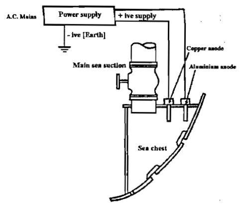
Dual-Anode Electrolytic Mechanism (Cathelco Principle)
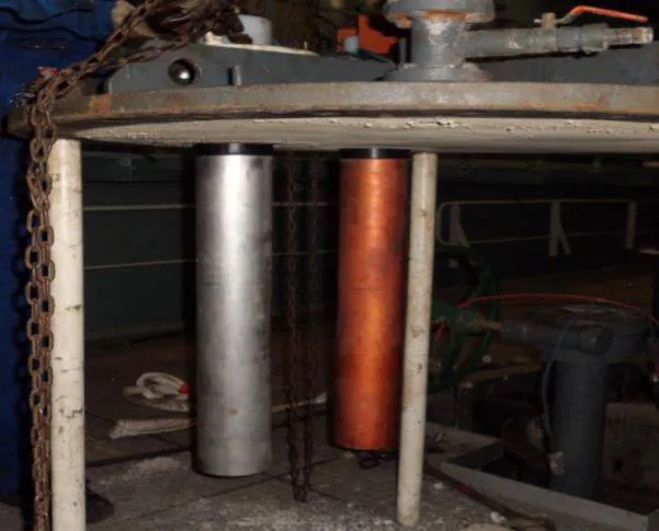
Pairs of specially alloyed anodes are mounted on flange mountings directly inside the sea chest recess, directly in the path of incoming water flow:
| Anode Type & Material | Electrolytic Chemical Reaction | Physical Action in Cooling System |
|---|---|---|
| Copper (Cu) Anode (Anti-Fouling Major Part) |
2H2O + 2e− → H2 ↑ + 2OH−
|
Copper ions are transported throughout the cooling system in microscopic concentrations (less than 2 parts per billion - ppb). This minute concentration is completely non-toxic to the wider ocean but creates an inhospitable environment that prevents barnacle and mussel larvae from adhering to pipe walls. |
| Aluminium (Al) Anode (Anti-Corrosion Supplementary Part) |
Al3+ + 3OH− → Al(OH)3 (gel precipitate)
|
Aluminium ions react with alkaline hydroxyl ions to form a gelatinous aluminium hydroxide precipitate. This flocculant travels with seawater, binding copper ions and depositing a micro-thin, alkaline anti-corrosive barrier film across all internal pipe walls, passivating copper-nickel (Cu-Ni 90/10) surfaces. |
Operational Current Settings
The MGPS control panel automatically adjusts DC amperage based on sea chest status:
- Active Duty Sea Chest: Delivers 2.5 to 3.0 Amps per anode to treat high-velocity seawater flow.
- Idle / Standby Sea Chest: Automatically cuts back to a trickle sleep current of approximately 0.4 Amps to prevent premature anode wastage while maintaining local protection.
5. Maintenance, Electrical Testing & Drydock Survey
Improper maintenance of sea chests and MGPS leads to rapid pipe degradation, catastrophic cooler fouling, and Class survey failure.
Monthly Operational Checks:
- Control Unit Amperage & Voltage: Record daily DC voltage (typically 3 to 12 V) and current (A). A sharp voltage increase indicates anode passivation or scale buildup; zero current indicates a blown fuse or severed wiring.
- Insulation Resistance Verification: Each anode mounting stud is electrically isolated from the ship hull by POM/PTFE dielectric sleeves and neoprene washers. During maintenance, check insulation resistance with a megger: resistance to hull must exceed 100 kΩ before cable connection. A short circuit to the hull renders the anode useless.
Drydock Overhaul Routine:
- Remove external sea chest grating; sandblast and inspect hull opening for cavitation pitting and welds for cracking.
- Inspect remaining anode diameter. Anodes must be renewed if consumed beyond 75% to 80% of their original diameter.
- Clean and inspect sea suction butterfly/globe valves; renew resilient rubber seat liners and packings.
- Verify clearing connections (blowdown non-return valves and steam injection orifices).
- Check zinc sacrificial anodes bolted to the sea chest interior corners to protect the bare steel hull box.
Found a mistake, or something unclear?
Report it in a few seconds — it goes straight to the editors.
- Ship Pipelines — Seawater, Bilge, Ballast & Fuel Systems
- Globe, Gate & Non-Return (SDNR) Valves: Working, Troubleshooting & Overhaul
- Butterfly Valves: Working, Construction, Troubleshooting & Overhaul
- Sea Chests (High/Low Suction) & Marine Growth Prevention (MGPS)
- Sea Chest Strainers: Construction, Standby-First Changeover & Safe Cleaning
- Pipe Corrosion, Water Hammer & Failure Response
- Steam Traps, Pressure Reducing Valves (PRVs) & Condensate Drainage