

Purifier Safety: Emergency Stop, Fire-Fighting & Vibration Response
Marine purifier safety: purifier room fire-fighting systems (Hypermist water-mist, quick-closing valves, remote trips, A-60 boundary), emergency-stop procedures, vibration response, and stored bowl energy.
1. Why the high-speed bowl is dangerous
A purifier bowl is not dangerous because it is hot or because it contains oil. It is dangerous because it stores energy. The bowl is a heavy mass spinning at several thousand revolutions per minute, and the energy it holds rises with the square of its speed:
E = ½ I ω²
where I is the moment of inertia of the bowl about its axis and ω is the angular speed. The arithmetic is not the point. The point is that the energy is released almost instantly if the bowl fails, and nothing in the machine is designed to stop it.
Three consequences follow, and they underpin every rule in this chapter.
- The energy cannot be switched off. Removing the motor supply stops the drive, not the bowl. The bowl coasts down on its own bearings and remains dangerous while it decelerates.
- The casing is a guard, not a container. The frame and cover keep hands out and contain normal leakage. They are not designed to absorb the release of a bowl's stored energy.
- Sludge changes the balance. A bowl that is balanced when clean becomes unbalanced as solids build unevenly on one side. At rated speed a small imbalance becomes a very large force.
Nobody stands alongside a running machine
- Never stand in line with the bowl while it runs.
- Never open the frame cover, a sludge plug or a sample cock while the bowl turns.
- Never reach over a discharge outlet during desludging.
- Keep the purifier room clear of loose tools and rags that can be drawn into a vent or a coupling.
Why part speed can be worse than full speed
There is one more reason the bowl demands respect. Every high-speed machine passes through one or more critical speeds, where the natural frequency of the rotating assembly matches the running speed and vibration is amplified. A bowl that is only slightly out of balance can vibrate far more violently while passing through a critical speed than it does at rated speed. That is why the maker's acceleration and stopping sequence is never hurried, and why a coasting bowl is left alone until it is completely at rest.
Safety comes before diagnosis
This chapter deals with the emergency response. The fault trees that explain why a machine misbehaves belong to Chapter 8. When a symptom is dangerous the response is the same every time: stop, isolate, then investigate. Do not continue running a machine to collect more evidence.
The standing rule is simple. When in doubt, stop the machine. A stopped purifier has never injured anyone; a running one can.
2. Emergency stop conditions
An emergency stop is a deliberate decision to abandon the controlled stopping sequence and remove the danger immediately. It is justified when continued rotation can turn a fault into an accident.
| Condition | Why it cannot wait |
|---|---|
| Excessive vibration or severe shaking | An imbalance can become bowl contact with a stationary part within seconds |
| Contact, rubbing or grinding sound | A rotating part is already touching something it should not |
| Abnormal bearing sound | Bearing failure escalates to seizure and bowl damage |
| Sudden large current rise | Mechanical drag or seizure; the overload may not act quickly enough |
| Failure to reach or hold rated speed | The bowl is unstable near a critical speed and separation has failed |
| Serious oil or water leakage | Hot oil under pressure, and a seal that is already damaged |
| Smoke, burning smell or electrical fault | Fire risk in an enclosed purifier room |
| Uncontrolled operation or a runaway sequence | The automatic logic is no longer protecting the machine |
| Failure of a critical safety device | Leakage monitor, discharge detector or zero-speed indication lost |
What is not an emergency
- A gradual drift in sludge-discharge interval or in oil quality.
- A small weeping joint or gland that is not worsening.
- A single water-detector alarm that clears and does not repeat.
- A current reading slightly above the settled value but steady.
These are reasons to plan an inspection, not to hit the button. But any of them that becomes sudden, severe, or is accompanied by sound or vibration is an emergency.
Do not delay an emergency stop to complete a sludge discharge, a replacement-water sequence, a clean-oil flush or a tank changeover. If continued rotation is dangerous, stop the machine first and deal with the consequences afterwards.
The decision rule
If the symptom is sudden, severe, or accompanied by sound, heat or leakage — stop. If the symptom is slow and stable — monitor and plan.
3. The emergency stop procedure
The emergency stop has one purpose: remove the danger as quickly as possible. Everything else is secondary, and the order of actions is part of the answer.
Feed is stopped first, so that no oil is trapped in a bowl that is about to become unstable. The drive is stopped second. Only then does the operator think about the machine.
What the emergency stop does at the panel
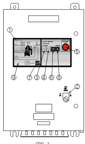
On an automatic machine, pressing EMERGENCY STOP normally:
- Cuts the automatic-running circuit immediately.
- Switches the feed valve to bypass, or closes it.
- Stops the motor without waiting for the normal sludge discharge.
On a manual machine the operator does the same three things by hand. In both cases the bowl coasts down with oil and sludge still inside, and that is accepted — safety takes priority over cleaning the bowl.
What not to do
- Do not open the frame cover, a sludge plug or a drain cock.
- Do not restart to see whether the fault settles.
- Do not reset an overload and continue without finding why it operated.
After the machine is safe
Record what happened while it is fresh: the time, the symptom, the panel indication, the current and speed at the moment of the stop, and the action taken. An emergency stop that is not recorded is an emergency stop that will be repeated.
4. High vibration and abnormal sound
This is the most examined safety question in the purifier syllabus, and the answer has two halves: the causes and the emergency action.
A high-speed centrifuge develops severe vibration. What causes it, and what are your emergency actions?
The causes
- Uneven partial discharge. A partial discharge that does not clear the bowl evenly leaves a sludge cake on one side. The bowl is then unbalanced, and the imbalance grows with every cycle.
- Worn spindle bearings. Wear allows the bowl axis to move, so the bowl runs out of true.
- A stripped worm wheel. Loss of drive integrity lets bowl speed fluctuate and the drive runs rough.
- A damaged disc stack. A bent, cracked or wrongly stacked disc set disturbs the balance of the rotating assembly.
Other causes that must not be forgotten: incorrect assembly, parts from different bowls mixed, a missing disc or distance piece, a relaxed disc stack, loose anchor bolts, a weak foundation, and a foreign object left in the bowl.
The emergency actions
- Press the emergency stop immediately. Do not monitor, do not wait, do not run the machine to gather more evidence.
- Feed neither water nor oil. Closing the feed stops oil entering a bowl that is already unstable, and prevents the machine being flushed while it is out of balance.
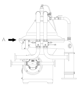
- Evacuate the immediate area. Keep everyone clear until the bowl is completely at rest. Do not open the cover or a sludge plug.
- Wait until the machine is completely at rest. Confirm zero speed by an approved indication.
- Then inspect the bowl. Only after isolation. Look for uneven sludge, disc damage, a damaged bowl part, bearing and spindle wear, and a loose foundation.
Never perform a normal sludge discharge during severe vibration. Opening the bowl while it is unstable can worsen the imbalance, damage the sealing surfaces and throw sludge uncontrolled.
Distinguish this from coast-down vibration
A bowl passing back through a critical speed during an ordinary stop can vibrate briefly. That is a transient and it decays as the speed falls. Vibration that begins suddenly at rated speed, that grows, or that is accompanied by contact or grinding sound is not a transient — treat it as dangerous. Abnormal sounds to act on include contact and rubbing, bearing-section noise, repeated knocking and a sudden grinding noise.
5. The safety joint
The safety joint is a deliberate weak link in the drive train. It is a shear or breakaway coupling, fitted in the horizontal drive — commonly on the gear-pump side of the worm wheel — so that if the torque needed to turn the bowl becomes excessive, the joint gives way instead of the gearing, the shaft or the bowl.
What it does
- It limits the torque that can be transmitted to the rotating assembly.
- It acts as a mechanical fuse: it fails before the expensive parts do.
- Because it is part of the visible drive, it is also used to confirm that the machine has stopped — if the gear-pump joint is not turning, the drive is at rest.
What its failure indicates
A broken safety joint is never the fault itself. It is the symptom of a fault that has already happened, and the question that must be answered before restart is: what made the torque excessive?
| Possible cause | What to check |
|---|---|
| Bowl contact with a stationary part | Bowl assembly, damaged parts, runout |
| Drive seizure | Bearings, gear case, lubricant condition |
| Gear problem | Worm wheel and worm shaft teeth |
| Bearing failure | Vertical spindle and horizontal shaft bearings |
| Foreign matter | Objects left in the bowl after an overhaul |
| Severe sludge imbalance | Sludge distribution and discharge history |
Do not simply replace the joint and restart. A joint that has broken once will break again until the cause of the excessive torque is found and corrected.
6. Hot oil, steam and operating water hazards
Even when the bowl is stopped, the purifier room holds three further hazards: hot oil, a live heating system, and water under pressure.
Hot oil and heating systems
- Fuel and lubricating oil at separating temperature can be close to 100°C. It does not need to look like steam to cause a serious burn.
- Stagnant oil in a heater that has been left running can overheat, degrade, and in the worst case ignite. Stop the heater when feed stops.
- Steam heating coils, tracing and relief lines are a burn and scald hazard. Never stand in front of a relief valve outlet, and never crack a hot flange.
- Open sample and drain cocks slowly. A sudden release of hot oil under pressure sprays.
Operating water under pressure
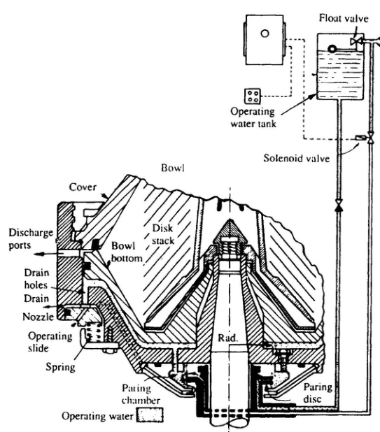
- Operating water opens and closes the bowl and is held at pressure in the tank, the pipework and the hydraulic chambers.
- The automatic valves can move without warning during a discharge cycle, even with the machine apparently idle.
- Sludge and water leave the discharge ports at high velocity. Never stand over an unprotected sludge outlet.
- Trapped pressure must be released before any hydraulic part is opened. A chamber that looks idle may still be holding water at pressure.
| Hazard | Where it comes from | Precaution |
|---|---|---|
| Hot fuel and lube oil | Heater, pipework, sample and drain cocks | Thermal gloves and eye protection; open cocks slowly |
| Overheated stagnant oil | Heater left running after feed stops | Stop the heater when feed stops |
| Steam and condensate | Heating coil, tracing, relief lines | Never face a relief outlet; check lagging for leaks |
| Operating water under pressure | Tank, solenoids, hydraulic chambers | Isolate and depressurise before opening anything |
| High-velocity sludge and water | Discharge ports during desludging | Keep the cover closed; never reach over an outlet |
| Cleaning chemicals | Bowl and disc cleaning | Use only maker-approved agents; gloves and eye protection |
Sludge is not harmless because it is only dirt. It is hot, it is often contaminated with fuel or lube oil, and it leaves the bowl at speed.
Never do these during a discharge
- Open the frame cover while the bowl rotates.
- Open a sludge plug during discharge.
- Put hands near the discharge ports.
- Bypass an interlock casually.
- Resume feed before the bowl is closed and sealed.
7. Electrical isolation and permit to work
No work is done on a purifier until it is isolated and a permit to work is in place. Isolation is not a single action — it is a sequence, and every step has a reason.
The isolation sequence
- Stop and confirm zero speed. Isolation protects against restart; it does not protect against a bowl that is still coasting. Zero speed comes first, by an approved indication.
- Isolate the electrical supply. Open the starter or breaker feeding the motor and its control panel. Remember the control panel and the Multi-Monitor may be fed separately.
- Lock off and tag. Apply a personal lock and a danger tag. A lock that only one person can remove is the whole point.
- Prove dead. Test the isolated circuit at the point of work. Test the tester before and after, so a faulty instrument cannot give false reassurance.
- Isolate oil, water and air. Close the feed and outlet valves, the operating-water supply and the air supply. Do not rely on a control valve that may be signalled open.
- Release trapped pressure and drain. Depressurise hydraulic chambers and pipework, and allow hot parts to cool before touching them.
The permit-to-work discipline
- A permit is a written record that the machine has been made safe and that named people are authorised to work on it.
- The permit states the isolation points, the work to be done, the precautions and the time limits.
- Isolation is not complete until the permit is issued and the isolations are confirmed at the machine.
- No one removes a lock, restores a valve or re-energises a circuit except under the permit system.
- On completion, the machine is checked, tools and rags are removed, the permit is cancelled, and only then is the isolation removed.
Why the sequence cannot be shortened
Each step removes one way the machine can hurt someone. Zero speed removes stored rotational energy. Isolation removes electrical energy. Locking off removes the human error of another watchkeeper. Proving dead removes the possibility of a back-feed. Closing valves removes stored fluid energy. Releasing pressure removes the energy held in a hydraulic chamber. Skip any one of them and the machine is still live in some form.
Never rely on a single isolator, on a control-room instruction, or on the machine being not in use. Lock off, tag, prove dead, and confirm at the point of work.
8. Post-stop isolation and restart
An unplanned stop is not the end of the incident. The machine is still holding oil, sludge and hot surfaces, and it may still be holding the cause of the stop.
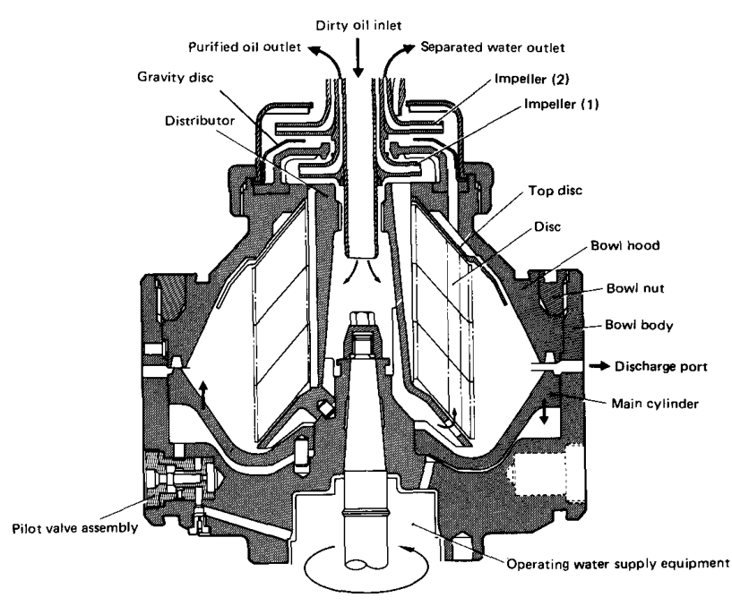
Confirm a complete stop
Never rely on the motor sound stopping. Confirm complete bowl stop with an approved indication:
- Gear-pump safety joint or motor fan — visible rotation
- Zero-speed indicator or speed display
- The maker's mechanical stop point
Vibration that persists as speed falls, contact sound, or a mechanical alarm means the stop was not clean. Keep clear and isolate.
Isolate before you touch it
After a complete stop: switch off and isolate the starter, close the feed and outlet valves, isolate the operating water, release trapped pressure, drain where the manual requires it, and secure the area. Record the shutdown condition.
Checks before restart after an unplanned stop
First, determine why it stopped. Then work through the checks.
| Category | Checks |
|---|---|
| Mechanical | Bowl assembly marks, disc count and order, bowl nut torque, no tools or rags left inside, sludge outlet clear |
| Hydraulic | Operating water available and at correct pressure, strainers clean, no leaks, opening and closing water confirmed |
| Electrical | Insulation and terminals, overload reset only after the cause is found, alarms cleared, interlocks proven |
| Operational | Start without feed, confirm acceleration and current, listen and watch for sound and vibration, confirm rated speed, establish the water seal, then introduce feed gradually |
Restart after a long stoppage
After a long stop the sludge in a lubricating-oil system can become denser. Expect a heavier load, use the maker's shorter discharge interval for the first period of running, and watch vibration and outlet quality before returning to the standard setting.
An unexplained stop is not restarted. Find the cause, correct it, and only then return the machine to service.
9. Purifier room fire-fighting systems & emergency safeguards
The purifier flat or enclosed purifier room is statistically the single highest fire-risk zone in a ship's engine room. Heavy fuel oil (HFO) is heated up to 98°C–130°C—well above its closed-cup flash point (typically 60°C)—and circulated under pressure right next to high-speed rotating machinery, electric driving motors, and thermal steam tracing.
Because any high-pressure oil leak can instantly atomize into an explosive flammable vapor or mist, marine regulations (SOLAS Chapter II-2) mandate a multi-tiered safety network combining structural containment, rapid remote isolation, and dedicated fixed local application fire-extinguishing systems.
1. Passive & Structural Fire Containment Safeguards
Before any active extinguisher operates, structural safeguards prevent fuel fires from spreading across the engine room:
- A-60 Gastight Fire Boundary: The purifier room is enclosed by steel bulkheads and deckheads insulated to A-60 standard. This prevents conductive heat transfer and blocks smoke/toxic gas ingress into escape trunks and adjacent flats.
- Self-Closing A-Class Fire Door: The access door is fitted with a heavy mechanical self-closing latch. Standing rule: Never wedge or tie the door open. A wedged door breaches the fire boundary, feeding oxygen to the fire and funneling thick smoke into the engine room.
- Save-All Coamings & High-Level Drain: Equipment is mounted inside a continuous steel save-all tray with at least 150°mm coaming height. Any drip, spray, or overflow is contained and led by gravity through a flame-screened pipe directly into the sludge or waste-oil tank. A float switch triggers a Save-all High Level Alarm on the ECR alarm panel before oil can spill over the deck.
- Anti-Spray Shielding (SOLAS Ch. II-2 Reg 4.2.2.5.3): All high-pressure fuel and lube oil piping joints, flanges, valves, and flexible connections must be wrapped with anti-spray tape or fitted with steel spray shields. This prevents pinhole gasket failures or loose union nuts from ejecting atomized fuel jets onto hot exhaust pipes, unlagged steam lines, or electrical junction boxes.
- Dedicated Exhaust Ventilation: Purifier rooms maintain negative pressure via an independent exhaust fan exhausting directly to the open weather deck, preventing flammable vapor build-up inside the machinery space.
2. Fixed Local Application Water-Mist System (Hypermist)
Under SOLAS Chapter II-2 Regulation 10.5.6, cargo ships of 2,000 GT and above with machinery spaces over 500 m³ must have a dedicated Fixed Local Application Fire-Fighting System protecting high-risk Category A machinery spaces, explicitly including the oil purifier flat.
| Feature | Hypermist Local Application Specification |
|---|---|
| Operating Principle | Dual action: Intense cooling via latent heat of vaporization (2,260 kJ/kg) + localized smothering as water droplets expand 1,700-fold into steam, starving the flame seat of oxygen. |
| System Pressure & Pump | Dedicated high-pressure positive-displacement plunger pump delivering fresh water at 70 to 140 bar (typical capacity ~200 L/min). |
| Nozzle Characteristics | Special diffuser nozzles produce micro-droplets (50–100 μm) at ~50 bar discharge pressure, delivering 12–20 L/min per nozzle directly over the purifier tops and heaters. |
| Activation Modes | UMS / Auto Mode: Dual-detector coincidence cross-zoning (must receive simultaneous alarm from 1 optical UV/IR flame detector + 1 optical smoke detector to discharge). Manned Mode: Manual release at the local cabinet directly outside the room entrance. |
| Critical Operational Advantage | Zero interruption: Hypermist can be discharged instantly without evacuating the engine room, without shutting down main propulsion or generators, and without tripping general engine room ventilation. |
Why not Total Flooding CO2 first? CO2 requires complete evacuation of all personnel, headcount verification, tripping all engine room fans, closing all dampers, stopping all machinery, and waiting for time-delay sirens. Local application water mist attacks the flame seat in seconds while keeping the ship navigable and crew safe.
3. Remote Isolation Safeguards (Fuel & Air Starvation)
Fire needs fuel and oxygen. When a purifier room fire occurs, external emergency controls starve both without entering the burning compartment:
- Purifier External Emergency Stop: A red emergency push-button situated immediately outside the purifier room entrance (and duplicated in the ECR). A single push instantly trips:
- The purifier bowl drive motor (removing mechanical heat and rotation).
- The independent fuel feed / booster pump (stopping fuel supply into the machine).
- The electric fuel pre-heater (removing the ignition source and boiling hazard).
- Quick-Closing Valves (QCV): Remote quick-closing valves installed on HFO/DO supply and return manifolds. Operated from outside the space (or Fire Control Station) via compressed air (pneumatic release cylinder) or mechanical pull wire. Pulling the purifier fuel QCV cuts fuel flow at the supply pipe boundary, isolating the leak.
- Ventilation Fan Trip & Fire Flaps: Remote electrical emergency stop switch outside the room trips the purifier room exhaust and supply fans. Counterweight fire dampers (flaps) on the ventilation ducts must be dropped immediately by releasing the external handle or fusible link wire to cut fresh combustion air.
4. Step-by-Step Emergency Response: Fire in Purifier Room
This is one of the most frequently asked practical emergency scenarios in MEO Class 4 & Class 2 Oral Examinations: "You are on watch and discover a fire in the purifier room. What is your immediate step-by-step action?"
Exam Caution — Do NOT use a straight water jet! Never use a sea water fire hose jet directly on an oil fire in the purifier room. High-velocity water will strike hot fuel, turn instantly into steam underneath the oil, and violently splatter flaming fuel across the entire compartment. Use fine water-mist (Hypermist), mechanical foam (AFFF), or dry powder only.
5. Extinguishing Media Comparison for Purifier Flat
| Extinguishing System | Type / Agent | Application Stage | Special Conditions & Precautions |
|---|---|---|---|
| Fixed Local Application (Hypermist) | High-pressure fresh water mist (~50 bar at nozzle) | 1st Line Fixed Defense | Operated locally or automatically via dual detectors. No evacuation or machinery shutdown needed. Extremely safe and rapid. |
| Portable / Mobile Foam | AFFF Mechanical Foam (9L portable or 45L wheeled unit) | Initial Attack (Incipient fire) | Forming an aqueous vapor-sealing blanket over burning oil pools in the save-all tray. Only if safe escape route is open. |
| Portable Dry Powder (DCP) | ABC / BC Dry Chemical Powder | Initial Attack | Breaks chemical chain reaction of flames. Causes low visibility and residue; protect airway. |
| Quick-Closing Fuel Valve (QCV) | Mechanical / Pneumatic isolation valve | Immediate Isolation | Cuts fuel supply to the room. Essential to prevent feeding unburnt fuel into the fire seat. |
| Total Flooding CO2 System | High-Pressure Liquid CO2 (85% fill ratio, 52 bar at 15°C) | Final Barrier (Catastrophic Breach) | Used ONLY if fire escapes purifier room and threatens entire engine room. Requires 100% crew headcount, machinery stopped, dampers sealed, and master valve release procedure. |
Standards & sources referenced
- SOLAS: International standards for the safety of life at sea.
- Conventions index
Found a mistake, or something unclear?
Report it in a few seconds — it goes straight to the editors.
- Purifier Principle: Centrifugal Separation & Stokes' Law
- Purifier Types: Purifier vs Clarifier, Disc vs Tubular
- Purifier Construction: Bowl, Disc Stack and Drive
- Purifier Working: Three-Phase Flow & Gravity Disc
- Purifier Operations: Start-Up, Running & Conditioning
- Purifier Maintenance: Cleaning, Inspection & Overhaul
- Purifier Safety: Emergency Stop, Fire-Fighting & Vibration Response
- Purifier Troubleshooting: Fault Diagnosis and Fixes