

Purifier Maintenance: Cleaning, Inspection & Overhaul
Purifier maintenance for MEO Class 4: bowl and sludge-space cleaning, disc-stack elasticity, O-ring and passage checks, spindle bearings and preservation.
Why maintenance is safety-critical
A purifier bowl is not a heavy tank with a lid on it. It is a comparatively thin-walled shell spinning at several thousand revolutions per minute, and its stored energy is the reason this chapter exists.
Every gram of that rotating mass carries kinetic energy. Approximating the bowl assembly as a rotating body:
E = ½ Iω²
where I is the mass moment of inertia and ω the angular speed. Energy rises with the square of speed, so a machine at rated speed holds far more energy than the numbers suggest. If a bowl fails, the release is violent and immediate — there is no warning and no second chance.
What the parts are asked to do
- Carry high centrifugal stress, continuously.
- Resist hot oil, water, sludge and abrasive fines.
- Resist corrosion and pitting, which concentrate stress.
- Seal hydraulic chambers with precision O-rings and machined surfaces.
- Open and close hydraulically, thousands of times over a service life.
- Stay in dynamic balance after every dismantling and reassembly.
A small defect does not stay small. It propagates quietly between services.
Two consequences follow for the engineer. First, the purifier must be maintained as a rotating pressure machine, not washed as a dirty tank. Second, a maintenance defect is not merely a performance issue — it is a potential structural failure of a machine holding enough energy to destroy itself and injure anyone nearby.
| Defect | Where it hides | What it becomes |
|---|---|---|
| Pitting or a crack | Under adhering sludge at the bowl wall | A stress raiser in the most highly stressed part of the machine |
| Worn or flattened O-ring | Inside a groove, invisible until removed | Operating-water leak, unstable bowl closing, oil carry-over |
| Blocked water passage | Behind a strainer or in a small orifice | Incomplete desludging and progressive bowl imbalance |
| Deformed disc or wrong count | Inside a compressed stack | Poor separation and vibration that no feed adjustment will cure |
| Misaligned tally marks | Only visible at assembly | Out-of-balance rotating assembly and loaded bearings |
Personal safety rules — isolation, permits, evacuation and the handling of a vibrating machine — are covered in the Safety chapter. This chapter deals with the condition of the machine itself.
Maintenance categories and planning
Purifier maintenance is easiest to remember as two families of work.
Running maintenance
Carried out with the machine in service or during a normal stop. It keeps performance stable between overhauls and gives the earliest warning of change.
- Watching sound, vibration, current and leakage.
- Programmed sludge discharge.
- Bowl washing, where the arrangement provides it.
- Checking operating-water pressure and strainers.
- Recording readings against the trend.
Planned maintenance
Carried out with the machine stopped, isolated and opened. It finds wear before failure and restores mechanical condition.
- Scheduled inspection of discs, O-rings, valve seats and passages.
- Overhaul of the bowl, spindle, bearings and seals.
- Corrosion inspection of high-stress parts.
- Suspension preservation and return-to-service inspection.
| Category | Purpose | Typical work |
|---|---|---|
| Routine observation | Detect change early | Sound, vibration, current, leakage |
| Operational cleaning | Keep performance stable | Bowl washing, sludge discharge |
| Planned inspection | Find wear before failure | O-rings, discs, valve surfaces |
| Overhaul | Restore mechanical condition | Bowl, shaft, bearings, seals |
| Corrosion inspection | Protect high-stress parts | Pitting, cracks, penetrant examination |
| Suspension preservation | Protect an idle machine | Drying, rust prevention, desiccant |
| Return to service | Verify readiness | Insulation, valves, oil, water, rotation |
How the interval is set
There is no universal purifier overhaul interval, and quoting one in an examination is a mistake. The interval is set by the maker's schedule and then adjusted by:
- Oil type. A fuel-oil purifier handling residual fuel sees catalyst fines, abrasive particles and a heavy sludge load, and may need frequent discharge and cleaning. A lubricating-oil purifier sees carbonaceous sludge, oxidation products and dense sediment after a long engine stoppage.
- Contamination load. Dirty bunkers, a poorly settled service tank or water ingress all shorten the practical interval.
- Running hours and duty. Continuous duty at high throughput wears the stack and seals faster than light duty.
- Trend readings. A rising current or vibration trend is evidence, and should pull the inspection forward.
| Driver | Effect on the practical interval |
|---|---|
| Residual fuel with high catalyst fines | Shortens it — abrasive solids load the sludge space quickly |
| Well-settled distillate or clean lubricating oil | Lengthens it — little free water and a light sludge load |
| Water ingress into the lubricating-oil system | Shortens it and demands investigation of the source, not just more cleaning |
| Continuous duty at rated throughput | Shortens it — the stack and seals work harder per running hour |
| Long engine stoppage before restart | Shortens the first interval — sediment settles and becomes dense and difficult to discharge |
| Frequent partial discharge or bowl washing | Lengthens the interval between physical overhauls |
What the record must contain
Date and running hours, oil treated, feed temperature and rate, discharge interval, bowl-cleaning date, disc count, O-ring replacement date, bearing condition, vibration and current readings, water pressure, and every fault with the action taken. A trend is almost always more useful than one isolated reading, and the maker's schedule overrides a convenient but unsuitable calendar interval.
Preparation before dismantling
Preparation is not paperwork. Most of the avoidable damage done to a purifier happens in the first ten minutes of an overhaul.
Confirm the machine is safe
- Complete the normal or emergency shutdown.
- Confirm the bowl has stopped — from the safety joint, motor fan or an approved zero-speed indicator. Never assume it has coasted down because the noise has changed.
- Switch off the starter and lock or tag the supply to ship procedure.
- Close the dirty-oil and clean-oil valves.
- Close the operating-water valves.
- Drain and depressurise the relevant piping.
- Allow hot parts to cool before handling.
Prepare the workplace and tooling
- Clean trays for small parts, and separate trays for each sub-assembly.
- Lint-free cloths, soft brushes and the approved cleaning liquid.
- O-ring lubricant approved by the maker — not grease from the engine-room shelf.
- Inspection lamp and magnifier.
- Torque tools, vernier and any specified gauges.
- New seals and consumables, laid out before work begins.
- A marking system for orientation, and the maker's assembly drawing.
Never place discs directly on a dirty deck, seals on metal chips, precision parts in an unmarked pile, or wet parts into a closed housing. Cleanliness protects both separation quality and bearing life.
Tally-mark discipline
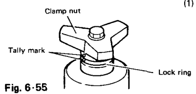
Bowl parts are individually balanced and carry tally marks. The bowl nut, the heavy-liquid chamber and the bowl body must go back together with their marks aligned. Treat orientation as a balance requirement, not as cosmetic neatness — the wrong angular relationship changes the mass distribution, increases vibration and loads the bearings unevenly.
Dismantle only with the maker's tools. A bowl hood lifted with improvised levers damages the hood, the top disc, the main seal ring, the disc stack or the bowl body — often several of them at once.
Cleaning the bowl and sludge space
Cleaning is the most frequent maintenance job and the one that most directly decides separation performance. Solids collect against the inside of the bowl wall; the disc passages, the sludge space and the discharge ports all narrow as deposits build.
What must be cleaned
- Bowl periphery and the whole sludge space.
- Sludge discharge ports and their full passages.
- Disc surfaces and disc holes.
- Distributor passages.
- Operating-water and sealing-water chambers.
- Every O-ring groove.
- Pilot-valve areas.
- Main-cylinder sliding and sealing surfaces.
The maker requires thorough cleaning before corrosion inspection, because sludge hides pitting, cracks, damaged sealing surfaces, blocked passages, distorted discs and damaged grooves. Never approve a part by inspecting it through a layer of sludge.
Cleaning without causing damage
- Do not hammer thin discs or prise them apart aggressively.
- Do not scratch or scrape machined sealing surfaces.
- Do not use uncontrolled grinding or abrasive blasting.
- Do not force a tool into an O-ring groove.
- Do not use a chemical that attacks the seals.
- Do not leave abrasive residue in a water passage.
Use the maker-approved method and cleaning liquid. After washing, rinse where required, remove all sludge and cleaning residue, blow or wipe the water out of every passage, and dry the parts completely. Moisture left inside the machine promotes corrosion, and moisture in electrical enclosures causes insulation problems later.
Sludge discharge ports
A discharge port is not clean because its visible mouth is open. The complete passage must be clear.
| Blocked port | Consequence |
|---|---|
| Partial obstruction | Incomplete discharge; residual sludge left in the bowl |
| Progressive build-up | Reduced effective bowl capacity and rising imbalance |
| Uneven obstruction | Abnormal vibration as one side of the bowl keeps its sludge load |
| Fully blocked ports | Failure of automatic discharge; sludge carried into the clean oil |
Disc stack inspection and elasticity
The disc stack sets the settling distance and the effective separating area, so its condition is a performance item as well as a mechanical one. Inspect every disc individually, on a clean tray, in the order it was removed.
What to look for on each disc
- Corrosion and pitting.
- Cracks — replacement is mandatory.
- Bent or torn edges.
- Deformed key grooves.
- Missing or damaged distance pieces.
- Loss of conical shape.
- Hardened deposits that will not come off.
Cracked discs are replaced, never welded, and welding is not permitted as a repair to a damaged disc. A defective disc changes the separation gap, disturbs flow between discs, creates local turbulence, reduces efficiency, can unbalance the bowl and can damage its neighbours.
| Disc defect | Effect | Action |
|---|---|---|
| Crack | Stress raiser; the disc can fail and damage the stack | Replace — welding is prohibited |
| Deformation or loss of cone shape | Discs touch, passage area falls, flow is disturbed, imbalance develops | Replace with a maker's disc |
| Deformed key groove | Disc moves or seats incorrectly on the distributor | Replace; review assembly method |
| Torn edge | Flow disturbance and possible crack initiation | Maker-approved dressing only if shape and thickness can be preserved |
| Hardened deposits | Passage area and effective separating area both fall | Remove by the approved cleaning method |
| Missing distance piece | Axial spacing changes; the stack cannot compress correctly | Fit the correct piece from the parts list |
Disc elasticity
Over service the stack can lose its original springiness. Discs that were not in close contact when new settle under bowl-nut tightening and centrifugal force, and a gap opens between the top disc and the set below it. Separation efficiency falls and the bowl may become unbalanced.
The maker normally permits one or more new discs to be added to close the developed gap, but the correct number must be taken from the maker's specification and disc figure. Never add discs by guesswork: excessive and insufficient stack height both create faults. A missing disc is not a minor omission — it changes stack height, compression, passage geometry, outlet flow and balance.
Order and assembly
- Keep every disc in its correct order; different discs differ in diameter, holes, profile and key arrangement.
- Align the key grooves and seat each disc fully on the distributor.
- Confirm distance pieces are present and that no disc is forced over a misaligned key.
- Confirm the specified disc count before closing up.
- Compress with the disc clamp plate, then tighten the bowl nut to the maker's method and torque.
- Confirm the finished stack is compact and even.
Poor disc setting is a recognised cause of key-groove deformation, especially in the upper discs. Small-diameter discs and distance pieces are fitted in the lower part on some models, so never transfer a disc arrangement from one purifier model to another without checking the maker's drawing.
O-rings, grooves and sealing surfaces
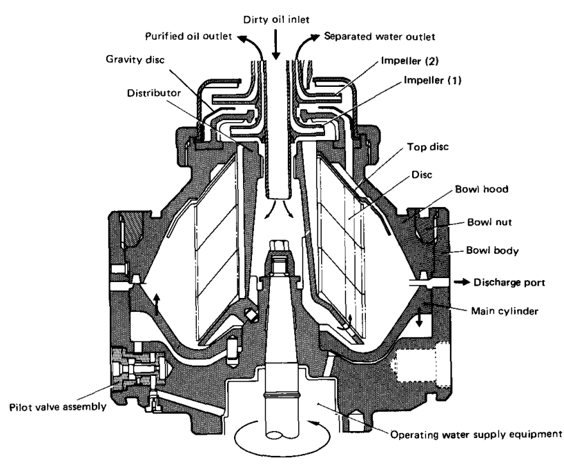
O-rings separate oil from water, oil from operating water, operating water from the drain, and the internal chambers from the frame. They seal the bowl hydraulic chambers, the water passages, the main-cylinder and pilot-valve sections, and the cover and body joints. Together with the machined surfaces they sit against, they decide whether the bowl seals, opens and closes at all.
| Seal | Keeps apart | Failure shows as |
|---|---|---|
| Main seal ring | Bowl interior from the operating-water side | Sealing-water leak, bowl failing to close |
| Chamber O-rings | Opening, closing and sealing-water chambers from each other | Unstable or partial bowl movement |
| Pilot-valve seals | Pressure side from the drain | Operating-water pressure decaying during the cycle |
| Cover and body joints | Internal chambers from the frame | Oil or water appearing on the frame |
| Outlet seals | Clean oil from separated water | Carry-over at the light- or heavy-liquid outlet |
Inspect every O-ring for
- Flattening and permanent set.
- Cuts, nicks and embedded particles.
- Hardening or cracking.
- Swelling.
- Any doubt at all — replace it.
Inspect every groove for
- Sludge, scale and rust.
- Burrs and scratches.
- Roughness.
- Deformation.
The maker requires every groove to be cleaned. A rough groove may be dressed with fine abrasive only within the specified limit; beyond that the part is replaced. The same applies to the machined sealing surfaces — the bowl hood seal surface, the main-cylinder sealing surface and the pilot-valve seat — where a scratch or a dent becomes a leak path under operating-water pressure.
Installation
- Confirm the correct size and material for that position.
- Clean the groove and the mating surface.
- Lubricate only with the approved lubricant.
- Fit without twisting, and without stretching it excessively.
- Keep it clear of sharp edges and threads.
- Confirm it is still fully seated after the parts are brought together.
Replace damaged or doubtful seals from the maker's parts list. Substituting an unapproved seal material, or reusing a hardened ring because it "looks all right", is how a clean overhaul becomes a repeat fault.
Operating-water passages and pilot valves
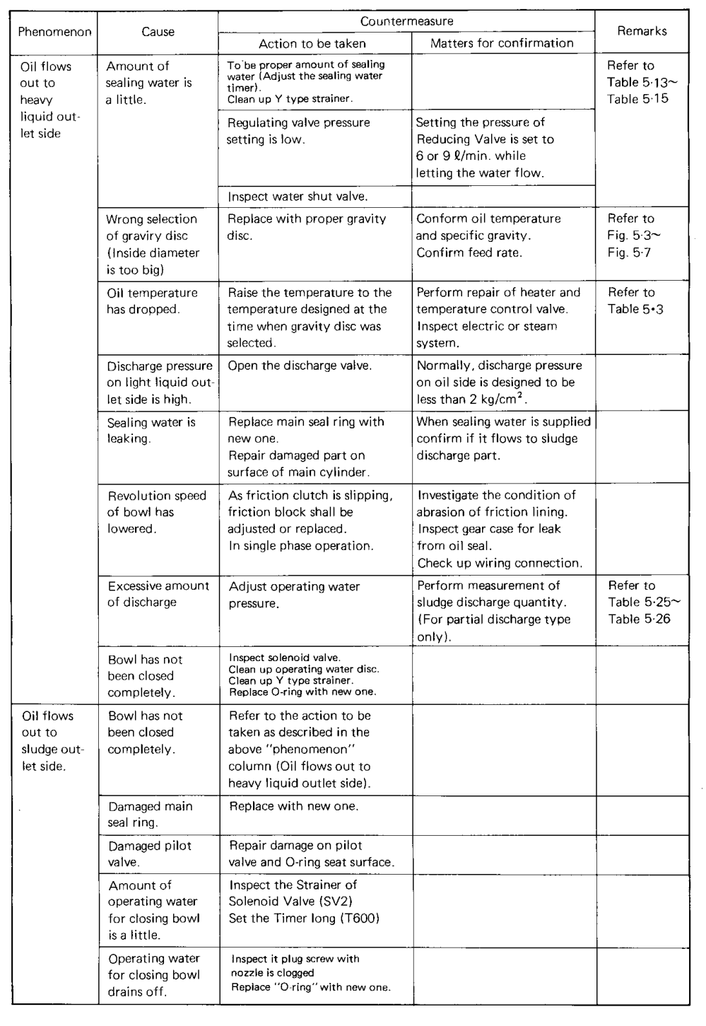
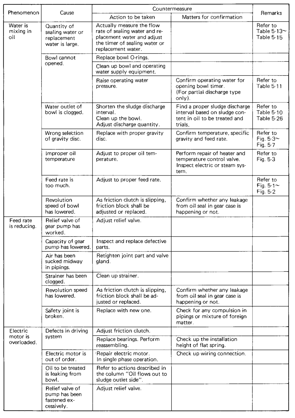
The hydraulic circuit is what makes a self-cleaning purifier possible, and it is the part most often neglected during cleaning. Scale and sludge restrict flow long before they block it completely.
Passages and components to clean
- Opening-water passage and chamber.
- Closing-water passage and chamber.
- Sealing-water passage.
- Replacement-water passage.
- Pilot-valve passages.
- Main-cylinder chambers.
- Strainers and small orifices.
The maker specifically requires clogged operating-water holes and the opening and closing water chambers to be cleaned. Blow them through and confirm flow, rather than judging by eye.
| Passage or component | Its job in the cycle | If it is restricted |
|---|---|---|
| Opening-water passage | Releases the sliding bottom for discharge | Bowl will not open; discharge missed or incomplete |
| Closing-water passage | Drives the bottom back up and holds it closed | Bowl closes late, or does not stay closed under load |
| Sealing-water passage | Re-establishes the liquid seal after discharge | Seal not maintained; oil escapes to the heavy phase |
| Replacement-water passage | Displaces oil from the bowl before discharge | Oil lost with the sludge; discharge quantity wrong |
| Pilot-valve passages | Switch pressure between the chambers | Erratic or delayed bowl movement |
| Strainers and orifices | Protect the small nozzles from debris | Progressive pressure loss and intermittent faults |
Symptoms of a restricted passage
- Bowl cannot open.
- Incomplete discharge, or discharge that sounds irregular.
- Bowl closes early.
- Water-detector alarm.
- Oil leaking to the sludge outlet.
- Water seal not maintained.
Pilot valves
Pilot valves switch the hydraulic pressure that moves the main cylinder. Inspect the sliding surface, the valve seat, the sealing surface, the O-ring, and confirm free movement with no foreign matter, deformation or scratches.
A damaged valve seat leaks operating water, and normal operation becomes impossible.
Clean the valve-seat surface and replace a seat deformed beyond the maker's limit. Most desludging faults that are not caused by low operating-water pressure trace back to a blocked passage, a dirty strainer or a leaking pilot valve.
Main cylinder and sliding bowl bottom
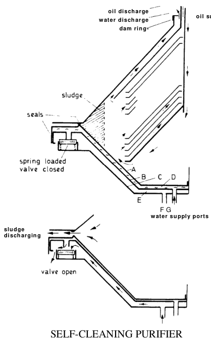
The main cylinder and sliding bowl bottom are the moving parts that make automatic discharge possible. The cylinder is held closed by closing water and is pushed open by opening water; the sliding bottom then drops and the sludge leaves through the ports at the bowl periphery.
Inspect
- The sealing surface that bears against the main seal ring.
- The sliding surface and its chrome-plated area.
- Scratches, dents and wear marks.
- Corrosion.
- The O-ring contact areas.
- Free, full travel of the sliding movement.
The maker warns that flaws on the sealing surface can damage the main seal ring, allow sealing water to leak, and disturb normal operation. If the cylinder does not move correctly, sludge stays in the bowl, the effective separation area falls, the bowl becomes unbalanced, gaskets are damaged, and the discharge cycle fails.
Handling
Take particular care when dismantling. A sealing surface is easily ruined by laying the component on a dirty or sharp surface, or by dropping it on the bowl body. Minor approved flaws may be dressed with an oilstone; major damage requires maker-approved repair or replacement.
| Part | Function | Failure symptom |
|---|---|---|
| Main cylinder | Hydraulically moves the sliding bottom | Bowl fails to open or fails to stay closed |
| Main seal ring | Seals the cylinder to the bowl hood | Sealing-water leakage; oil to the sludge outlet |
| Sliding bowl bottom | Opens the discharge path when released | Incomplete discharge; residual sludge; imbalance |
| Discharge ports | Pass the sludge out of the bowl | Partial or no discharge; vibration |
Dress a minor flaw only within the maker's limit and never in a way that changes the sealing geometry. A sealing surface that has been "cleaned up" until it no longer seats is worse than the original defect.
Vertical spindle, bearings and gear case
Bowl speed and balance depend on the spindle and its bearings. The vertical spindle carries the bowl through a high-speed flexible connection; the horizontal shaft and worm drive it from the motor; the gear case and its gear pump provide lubrication.
Vertical spindle and bearings
Inspect for scoring, wear at the contact surfaces, fretting, corrosion, runout or deformation, bearing noise, lubricant contamination, and damaged springs or supports.
Bearings must be the specified type. Substituting an unapproved bearing changes the clearance, the load capacity and the high-speed reliability of the machine, and it is not a decision for the engine-room store.
Symptoms of spindle or bearing trouble
- Rising vibration and abnormal sound.
- Current increase.
- Slow acceleration, or failure to reach rated speed.
- Oil leakage at the shaft seal.
- Excessive heat at the bearing housing.
When a shaft or bearing fault is suspected, do not continue running "to see whether it settles".
| Component | Inspect for | Evidence of wear |
|---|---|---|
| Vertical spindle | Scoring, fretting, corrosion, runout | Runout on a dial gauge; polished or discoloured contact bands |
| Spindle bearings | Type, clearance, lubricant condition | Noise, heat at the housing, slow acceleration |
| Bearing springs and supports | Damage, correct fit, freedom | Bowl not settling correctly; vibration at speed |
| Worm gear and pinion | Pitting, scoring, tooth form | Metallic particles in the gear-case oil; abnormal note |
| Gear-case oil | Level, colour, water, sludge | Emulsified or milky oil; sludge in the sump |
| Gear pump and connecting tube | Gear condition, blockage, oil trapped in the tube | Low oil delivery; oil draining into the pump on reassembly |
Horizontal shaft, gear case and gear pump
- Inspect the worm gear teeth and the pump gears for pitting, scoring and wear.
- Check shaft seals, couplings and the safety joint.
- Check the gear-case oil for correct level, condition and contamination.
- Check the pump connecting tube for oil, water or sludge.
Water in the gear case indicates a sealing or drainage problem and must be investigated before the machine is run again. The gear pump must be clean and lubricated as specified, and during long suspension the accumulated oil in the connecting tube must be removed so that it cannot flow into the pump during reassembly.
Clearances, bearing types, gear-case oil grade and replacement intervals are all maker-specific. Take them from the installed machine's manual rather than from a general rule of thumb.
Bowl washing during operation
Lubricating-oil purification normally includes a bowl-washing step that fuel-oil purification does not. The purpose is to remove the residual solids that remain after the main sludge discharge — solids that would otherwise harden in place.
The maker states that washing water is introduced into lubricating-oil purifiers at predetermined intervals, and that no washing water is required for its fuel-oil arrangement. The quantity and the interval are model-dependent; never use a figure taken from another model.
If bowl washing is omitted
- Solids remain in the bowl after discharge.
- Separation performance declines steadily.
- Deposits harden and become difficult to remove at the next overhaul.
- Mechanical trouble may develop from the retained imbalance.
Fuel oil versus lubricating oil
| Feature | Fuel-oil purifier | Lubricating-oil purifier |
|---|---|---|
| Nature of sludge | Fuel sludge, catalyst fines, abrasive solids | Wear particles and oxidation products |
| Bowl washing | Generally not required | Programmed at the maker's interval |
| Discharge pattern | Water separation may use partial discharge | Total discharge followed by washing |
| Interval behaviour | Set by sludge load and fines content | May need shortening after a long engine stoppage, when solids become dense |
Select the washing routine for the liquid actually being treated, not simply for the model of purifier installed.
Long-term preservation and return to service
If a purifier will not be used for more than three months, it needs preservation rather than simply being left shut down. The Mitsubishi suspension procedure follows this logic.
Preservation
- Disassemble and clean the frame and sludge cover.
- Remove moisture completely.
- Apply rust-preventive oil to the inside surfaces.
- Clean and lubricate the bowl.
- Apply rust-preventive oil to the outside of the bowl.
- Store the bowl separately, rather than reassembling it on the vertical shaft.
- Clean, protect and reassemble the vertical and horizontal shafts.
- Clean the gear case and apply rust-preventive oil; do not refill with lubricating oil until starting.
- Clean and lubricate the gear pump, and drain the oil from the connecting tube.
- Drain the operating-water piping.
- Seal the electrical equipment against moisture and place desiccant in the starter, control panel and Multi-Monitor.
- Close the sludge-outlet butterfly valve.
Why the bowl is stored separately
- It reduces the load carried by the shaft during long inactivity.
- It allows the protected surfaces to be inspected.
- It prevents moisture from being trapped in the assembly joints.
- It makes the preservation status of the machine visible at a glance.
The procedure must be followed exactly, because the bowl and shaft are precision rotating components that depend on each other's geometry.
Attention during suspension
- Turn the vertical shaft by hand for two or three minutes at least weekly — this prevents one-position bearing deterioration and reveals stiffness or abnormal resistance.
- Carry out quarterly bearing-centred inspections and six-month periodic inspections.
- Renew rust-prevention measures and replace the desiccant at the prescribed interval.
Electrical preservation is a matter of keeping the equipment dry: desiccant in place, enclosures sealed, and an insulation check before re-energising. Never energise a damp panel merely to see whether it still works.
Return to service
| Area | Checks before running |
|---|---|
| Mechanical | Remove preservation oil where required; confirm bowl and shaft assembly; confirm disc count and stack; check all O-rings; check bowl nut and fasteners; confirm no tools or cloths remain inside; confirm the sludge outlet is clear and valves move freely |
| Hydraulic | Reconnect operating-water piping; open the source valve; check for leaks; clean strainers; confirm opening, closing, sealing and replacement water |
| Electrical | Renew desiccant; insulation check; inspect terminals and coils; confirm panel functions; reset alarms |
| Operational | Start without feed; confirm acceleration and current; check sound and vibration; confirm rated speed; establish the water seal; introduce feed gradually; confirm outlet quality and pressure |
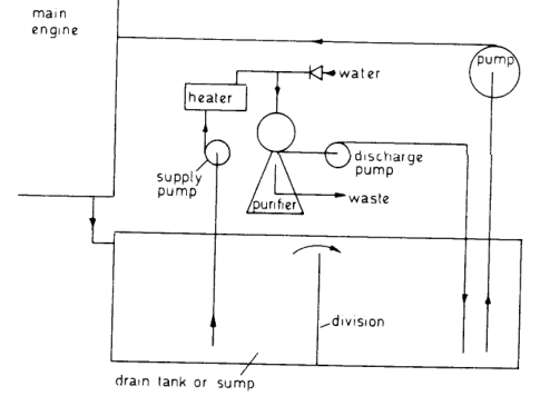
Assembly quality decides the next running period. Correct part, correct orientation, correct seal, correct disc count, correct tightening, correct clearance and a clear water path must all be right together — one wrong step undoes the rest. Use a signed checklist for critical bowl assembly, and take every torque and clearance from the installed machine's manual.
Found a mistake, or something unclear?
Report it in a few seconds — it goes straight to the editors.
- Purifier Principle: Centrifugal Separation & Stokes' Law
- Purifier Types: Purifier vs Clarifier, Disc vs Tubular
- Purifier Construction: Bowl, Disc Stack and Drive
- Purifier Working: Three-Phase Flow & Gravity Disc
- Purifier Operations: Start-Up, Running & Conditioning
- Purifier Maintenance: Cleaning, Inspection & Overhaul
- Purifier Safety: Emergency Stop, Fire-Fighting & Vibration Response
- Purifier Troubleshooting: Fault Diagnosis and Fixes