

Purifier Operations: Start-Up, Running & Conditioning
How a marine purifier is started, run and stopped: pre-start checks, water seal, feed temperature and rate, normal running values, automatic timers, fuel heating and oil conditioning.
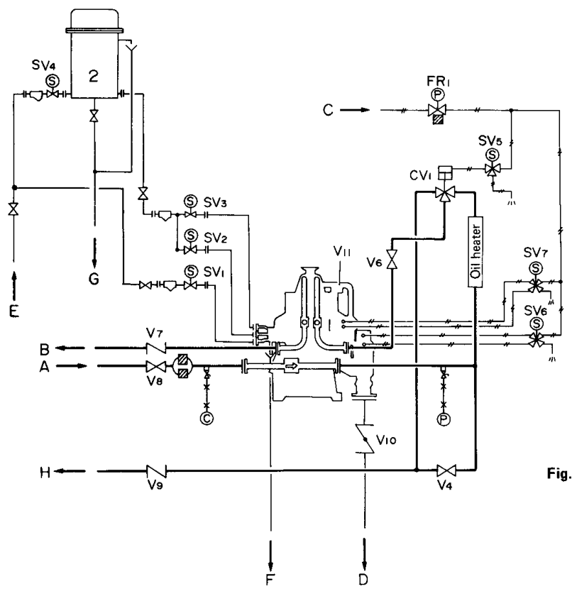
1. Pre-start inspection
Nothing is started until the machine and its services are confirmed ready. The inspection covers five groups.
| Group | Confirm before starting |
|---|---|
| Mechanical | Bowl correctly assembled; bowl nut secured; frame cover fitted and locked; disc stack correctly stacked; correct gravity disc fitted for the oil; no tools or foreign objects left inside; spindle and drive ready; foundation fasteners tight |
| Valves and lines | Dirty-oil inlet, clean-oil outlet, bypass, flow-control, circulation, butterfly and feed valves in the correct position; water shut valve set; sludge and separated-water outlets open and safe |
| Water system | Operating-water tank filled; sealing and replacement water available; operating-water pressure correct; water strainers clear; solenoid valves free to operate; drain lines open |
| Oil system | Correct oil source selected; supply tank has sufficient oil; heater ready; feed pump available; temperature instruments working; bypass and circulation routes available |
| Control and safety | Starter ready; automatic panel powered; alarms healthy; emergency stop available; leakage monitor ready; interlocks not bypassed; discharge timer set |
The exact valve numbers, water quantities and pressures are model-specific. The maker's manual and the shipboard procedure always take priority over any general list.
Why the inspection is not optional
A purifier carries a heavy bowl at high speed, hot oil, water under pressure and accumulated sludge. A rushed start does not save time; it moves the fault to a moment when the machine is already rotating. The common consequences of a skipped inspection are an incorrectly stacked disc set that unbalances the bowl, a gravity disc that does not match the oil, a closed valve on the outlet path, an empty operating-water tank that prevents the bowl from closing, or a bypassed interlock that lets feed in before the machine is ready. Each of these is quick to check and expensive to discover at speed.
2. Start-up to rated speed
The start-up sequence must establish four conditions in the correct order: the bowl can rotate safely, the oil is at the right viscosity, the bowl is closed and sealed, and oil then enters at the right rate and reaches the right outlets.
What happens during acceleration
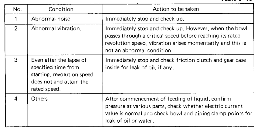
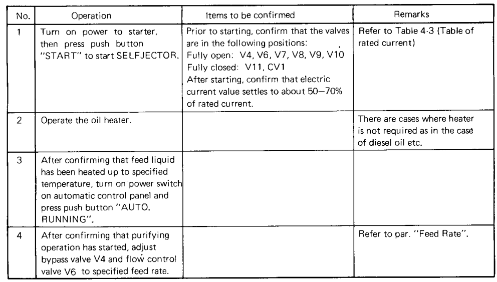
The motor current is high at first and falls as the bowl approaches speed. Temporary vibration may occur while the bowl passes through a critical speed; this should reduce at rated speed. Rated speed is normally reached several minutes after start, but do not use elapsed time as proof of speed — confirm the speed or operating indication.
Why feed must not be admitted early
- Centrifugal force is insufficient. Acceleration rises with the square of speed, so below rated speed there is not enough force to separate anything reliably.
- The bowl cannot be closed or sealed hydraulically. The closing and sealing sequence depends on full speed.
- The water seal cannot form. Without it, oil has nothing to hold it on the light side of the interface.
- The outlet impellers do not generate their design pressure, so the liquid balance is wrong.
The practical rule is simple: no oil into a purifier that has not reached speed, temperature and hydraulic readiness. Any abnormal sound, rubbing, large vibration, leakage or failure to accelerate is a stop-now condition, not something to watch.
Normal start-up current and vibration
| Condition | Normal | Abnormal |
|---|---|---|
| Current during acceleration | High at first, then settling as the bowl reaches speed. The manual gives a typical settled value of about 50–70% of rated current for the referenced equipment | High current that does not settle: mechanical friction, bearing or drive fault, incorrect bowl assembly, motor fault or low voltage |
| Vibration | Brief vibration while passing a critical speed, reducing at rated speed | Persistent or large vibration at rated speed: unbalanced sludge, incorrect disc assembly, damaged bowl part, bearing damage, spindle problem, bowl rubbing or a loose foundation |
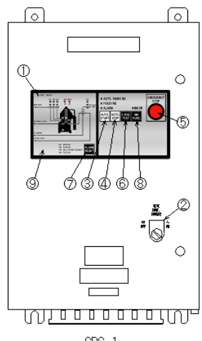
When an automatic panel is fitted, pressing AUTO START runs the programmed sequence once rated speed is reached — typically discharge, seal, then feed. Watch the discharge sound or current change, the water-valve operation, bowl closing, the sealing-water supply, feed-valve movement, and the response of both outlets.
3. Establishing the water seal
Sealing water is supplied after the bowl is at speed and correctly closed. Its purpose is to establish the heavy-liquid region, prevent oil escaping through the heavy-liquid outlet, prepare the oil-water interface and stabilise the machine before feed.
Why the order matters
The fundamental purifier sequence is operating speed, fresh water for the water seal, then oil feed. The order is not a convention — it is the physics. The seal fills the outer region with water and defines where oil and water will meet. If oil arrives first there is no heavy phase to hold the interface: the interface never forms, there is no separation, and the oil is lost through the water outlet to the sludge side. Seal before the feed and the interface forms at the correct radius, the oil leaves by the light-liquid outlet, and the separation is stable and repeatable.
Water-seal checks
- Water reaches the correct inlet and the flow is not excessive.
- No water leaks from unintended locations.
- The water outlet responds normally.
- The correct gravity disc is installed for the oil at separating temperature.
- The bowl is fully closed and the discharge ports are shut.
A bowl that is not fully closed must not be fed normally. It can leak oil, water or sludge, and the fault must be corrected before the machine is put on line.
What a lost seal looks like
The seal can be lost in service as well as at start-up. The operator sees oil discharging continuously from the water outlet, a sudden fall in clean-oil outlet pressure, or water appearing in the clean oil. The immediate operational response is to take the feed off the machine and re-establish the seal before normal feed is resumed. Fault diagnosis of a seal that will not hold belongs to the Troubleshooting chapter.
4. Feed temperature and the separating value
Temperature is the operator's main lever because it is the only term in Stokes' law that can be changed from the control panel without touching the machine. Heating lowers viscosity, and viscosity is the drag that resists every droplet and particle on its way outward.
Set the viscosity, not a temperature from memory
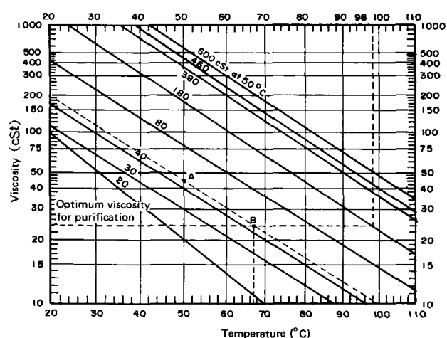
The target is a viscosity at the bowl, found from the maker's temperature-viscosity graph for that oil. The Mitsubishi manual uses approximately 24 cSt as the optimum condition for its example and limits the maximum heating temperature to below about 100 °C for that arrangement.
| Liquid | Stated viscosity condition | Reference treating temperature |
|---|---|---|
| A heavy oil | 14 mm²/s at 40 °C | 40 °C |
| C heavy oil | 180–700 mm²/s at 50 °C | 98 °C |
| Lubricating oil, SAE 30 | 100 mm²/s at 40 °C | 74–90 °C |
| Lubricating oil, SAE 40 | 150 mm²/s at 40 °C | 83–95 °C |
These are manual examples, not universal settings. The actual value depends on the installed model, the oil type, the oil's viscosity curve, the maker's target viscosity and the maximum permitted temperature.
Worked example from the manual
For a fuel of 45 cSt at 50 °C, the maker's graph gives a treating temperature of approximately 67 °C to reach the target of about 24 cSt. The method is to locate the known point, follow the oil's viscosity relationship, find where the oil reaches the target viscosity, and read off the temperature. This does not mean every fuel is heated to 67 °C — it applies only to the stated viscosity and that machine's graph.
Temperature does two things at once
- Flow effect. Lower viscosity means less drag, easier movement of water and solids, and higher practical throughput.
- Interface effect. Heating also lowers oil density, which changes the radial balance between oil and water and can move the interface. A temperature change can solve a viscosity problem and create an interface problem.
Risks of overheating
- Oil deterioration and increased oxidation rate.
- Damage to seals and non-metallic components.
- Excessive thermal stress and wasted energy.
- Fire hazard from hot oil in the presence of a leak.
- Interface shift, because density has fallen further than intended.
Do not adjust the gravity disc to compensate for a heater fault. Correct the temperature first, then re-check the interface.
5. Feed rate and outlet pressure
Feed rate sets how long the liquid stays in the separation chamber. That residence time is what gives each droplet and particle the chance to migrate outward, so feed rate controls the limit-size particle directly.
Feed rate versus rated capacity
- Feed rate — the operating flow selected for the moment.
- Rated capacity — the nominal machine capability under standard conditions.
- Best separation rate — the flow that produces the cleanliness actually required. This is usually well below rated capacity for difficult contamination.
A machine may accept a high feed rate while producing poor separation at that rate. A sudden full feed at start-up can displace the interface, overload the bowl and send water into the clean oil, so feed is opened gradually while both outlets are watched.
| Feed rate | What happens |
|---|---|
| Too high | Residence time falls, fine solids pass through, water separation deteriorates, the interface becomes unstable and outlet pressure changes |
| Too low | Treatment capacity falls, oil stays heated longer than necessary, the system may not meet demand, and very low flow can upset automatic-monitor settings |
| Correct | Meets both the treatment capacity required and the oil cleanliness required |
Set the rate from an actual flow indication where one is fitted, adjust the bypass and flow-control valves only after purification has started and current has settled, and reduce feed if clean-oil quality is poor. Record the stable operating rate.
Light-liquid outlet pressure
The purified-oil discharge line carries a back-pressure control valve. The Mitsubishi manual gives a standard example of approximately 0.15 MPa (1.5 kgf/cm²) for the referenced system, but the correct value must come from the installed manual.
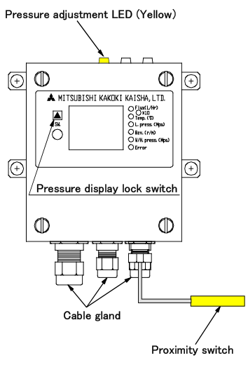
Outlet pressure affects oil discharge, internal hydraulic balance, interface condition and the leakage monitor. The manual states that light-liquid outlet pressure is critical for correct leakage-monitor operation, and that once set during trials it normally needs no further adjustment unless flow rate or temperature fluctuates.
Do not use outlet pressure to hide a wrong gravity disc, a poor water seal, a blocked outlet, an incorrect temperature or an excessive feed rate.
6. Normal running values
Normal operation is the sum of correct mechanical, thermal, hydraulic and separation conditions together. Monitor these values throughout the watch.
| Value | Normal indication | What a deviation means |
|---|---|---|
| Bowl speed | Stable at rated speed | Low or fluctuating speed means insufficient centrifugal force — stop normal feed |
| Motor current | Settled and stable, within the maker's range | Rising current suggests bearing friction, bowl rubbing, sludge build-up or pump load; unstable current suggests clutch slip or drive fault |
| Vibration | Low once acceleration is complete | Large or persistent vibration at rated speed is abnormal — stop and investigate |
| Operating sound | Consistent after acceleration | Rubbing, knocking or harsh bearing noise is a stop-now condition |
| Feed temperature | Stable at the selected separating value | Low, high or fluctuating temperature changes viscosity and can disturb the interface |
| Feed rate | At the planned value | Too high reduces residence time; too low reduces capacity and may affect monitor settings |
| Feed pressure | Stable pump pressure, no air in the suction | Low pressure means empty tank, pump wear, blockage or air leak; high pressure means restriction or excess viscosity |
| Light-liquid pressure | Correct preset range | Low or high pressure disturbs the interface and the leakage monitor |
| Water outlet flow | Water leaving according to the oil's water load | Oil carry-over or no flow at all both indicate an interface or outlet problem |
| Clean-oil quality | Dry and clean, no haze or sediment | Water, cloudiness or fine solids mean temperature, rate, disc, seal or stack condition is wrong |
The five groups to watch
- Mechanical — vibration, sound, motor current, bowl speed, bearing temperature, oil leakage.
- Thermal — heater inlet and outlet temperature, feed temperature at the purifier, temperature-control stability.
- Hydraulic — feed pressure, clean-oil outlet pressure, water outlet flow, operating-water pressure, sealing-water quantity.
- Separation — oil at the water outlet, water in the clean oil, solids in the clean oil, sludge-discharge behaviour, interface stability.
- Control — alarm state, leakage monitor, discharge timer, valve positions, feed-valve status.
Confirm sludge discharge by an approved indication — a current change, discharge sound or detector response. A timer reaching zero is not proof that discharge occurred. Do not increase feed immediately after discharge just because the outlet looks temporarily clear.
7. The operating log and trends
A purifier log records trends, not isolated values. Record at start, once stable, after each discharge and at the end of the watch.
| Time | Speed | Current | Feed temp. | Feed rate | Light-liq. press. | Water outlet | Vibration | Discharge | Remarks |
|---|---|---|---|---|---|---|---|---|---|
| Start | |||||||||
| Stable | |||||||||
| After discharge | |||||||||
| End of watch |
Also record alarm events, valve adjustments, any change of fuel or oil, heater changes, discharge observations, clean-oil quality and any change in sound or vibration.
Why trends beat single readings
A single normal reading proves only that the machine was normal at that instant. A slow rise in current or vibration may reveal deterioration long before an alarm operates. A gradual change in outlet pressure may indicate flow restriction, a temperature change, an interface shift, pump wear or leakage.
| Trend | Likely meaning |
|---|---|
| Rising current over hours | Mechanical drag, sludge accumulation, pump load, bearing wear |
| Falling speed | Clutch slip, motor fault, bearing or overload problem |
| Increasing no-discharge alarms | Hydraulic restriction, sludge blockage, sensor problem |
| Increasing leakage alarms | Seal wear, pressure instability, bowl-closure fault |
| More frequent water alarms | Interface shift, water flow, seal or detector problem |
The log exists so that a change can be seen while it is still small. Change one lever at a time and record the result; a purifier adjusted in several ways at once cannot be diagnosed afterwards, and the same discipline underlies the Troubleshooting chapter.
8. Automatic control panel and timers
Manual operation of every valve would be too slow and too vulnerable to timing error. The panel coordinates the same operations every cycle through timers, relays, solenoids, sensors and interlocks.
Panel controls
- AUTO START — begins the predetermined sequence once rated speed is reached.
- AUTO STOP — switches feed to bypass, performs replacement water and sludge discharge, cuts the automatic circuit, then stops the motor.
- EMERGENCY STOP — cuts the automatic circuit, bypasses feed and stops the motor without waiting for normal discharge. (Emergency logic belongs to the Safety chapter.)
- DISCHARGE TEST — forces the interval timer to time up while feeding, so a discharge can be tested.
Solenoid-valve unit
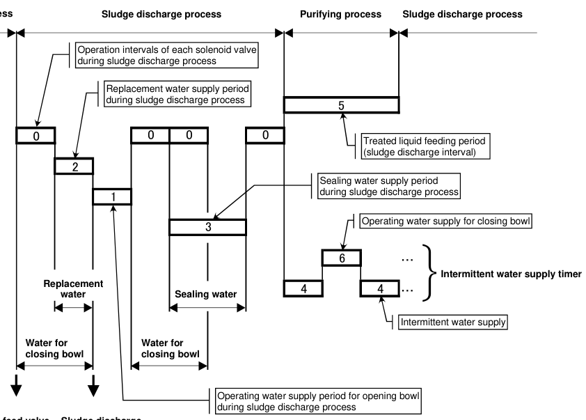
The controller output energises a solenoid coil, the valve spool shifts, operating water flows, and the bowl hydraulic position changes. The unit supplies opening water, closing water, sealing water, replacement water and, where fitted, regulating water. Triple-solenoid units give total discharge; quadruple units give total and partial discharge.
Timer-controlled operations
Timers set the duration or interval of the feed period, sealing water, replacement water, opening water, closing water, partial-discharge water, bowl washing, intermittent water supply, the discharge interval, detector reset and the alarm monitoring delay.
Q = q × t
where Q is the water quantity, q the actual flow rate and t the valve-open time. A timer sets valve-open time, not water quantity. If operating-water pressure or a restriction changes the flow, the same timer delivers a different quantity, and bowl opening, closing or discharge changes with it.
| Timer type | Function |
|---|---|
| Interval timer | Determines when discharge occurs |
| Pulse timer | Determines valve-on duration |
| Delay timer | Allows pressure or speed to stabilise |
| Counter | Counts discharge or washing events |
| Monitoring timer | Defines the alarm confirmation period |
Timer tables differ for purifier model, total- or partial-discharge mode, fuel or lubricating oil, bowl size and panel type. Before changing any timer, record the timer number, original value, new value, reason, date, operator and result, then test the bowl opening, closing, discharge quantity, seal restoration, alarm response and absence of oil loss.
Standard timer values are guidelines based on a specified flow rate. Measure the actual operating-water flow before setting timers, and never copy timer values from another purifier model without checking the flow.
Manual versus automatic mode
| Mode | Advantages | Risks |
|---|---|---|
| Automatic | Repeatable sequence, reduced workload, integrated alarms, automatic discharge, detector feedback | An incorrect timer affects every cycle; a failed sensor can mislead the controller; operators may trust lamps instead of the machine |
| Manual | Useful for commissioning and fault-finding; allows individual valve testing and confirming water paths | Wrong valve order can damage the process; feed may continue during an unsafe action; an interlock may be bypassed |
Automatic mode is normal running. Manual mode is for testing and diagnosis only, used by authorised personnel following the maker's sequence.
9. Fuel heating and Viscotherm control
Residual fuel is heated for two different reasons, at two different places, and the two must not be confused.
Why viscosity, not temperature, is controlled
What the engine needs is a fuel of the right viscosity at the injectors, so it atomises into a fine spray. Viscosity, not temperature, controls atomisation, spray penetration and combustion quality. But the viscosity of a residual fuel at a given temperature varies widely with the bunker batch — a fuel that gives the correct viscosity at 130 °C may give a far too thick fuel at the same temperature if it is a heavier blend. A fixed temperature therefore does not give a fixed viscosity, and as bunker quality varies, temperature control drifts away from the target.
A Viscotherm regulator solves this by measuring actual viscosity and modulating the heating. The principle is simple: a measuring element in the fuel line — a capillary or a small gear-and-spring arrangement — responds to the real viscosity of the flowing fuel, and its output positions a control valve on the steam or thermal-oil supply to the heater. If the fuel thickens, the valve opens and heating increases; if it thins, heating falls. The result is a constant injection viscosity whatever the bunker quality.
Why viscosity control wins when bunker quality varies
Two ships can burn fuels from different suppliers with the same nominal grade and find that the same heater temperature gives very different injection viscosities. The heavier blend needs more heat, the lighter blend needs less. A temperature-controlled system cannot tell the difference, so it either over-thins the light fuel or leaves the heavy fuel too thick. A Viscotherm regulator closes that gap automatically: it does not care what the fuel is, only how thick it is at the moment.
| Injection viscosity | Consequence |
|---|---|
| Too high (fuel too thick) | Poor atomisation, large droplets, long spray penetration, late and incomplete combustion, carbon deposits, smoky exhaust, higher specific fuel consumption |
| Too low (fuel too thin) | Over-fine spray, short penetration, poor mixing with air, loss of lubricity at the fuel pump and injector, risk of pump wear |
| At the target | Correct atomisation, good mixing, complete combustion and steady injection timing |
Notice that this is a combustion argument, not a purifier argument. The engine needs a viscosity; the purifier needs a temperature. They are set from different documents, and neither substitutes for the other.
Typical values
| Setting | Typical figure | Set from |
|---|---|---|
| Injection viscosity at the engine | About 10–15 cSt for modern two-stroke engines | Engine maker; held by the Viscotherm regulator |
| Purifier separating temperature | Its own figure — around 98 °C for residual fuel, never above the purifier maker's limit | Purifier maker's temperature-viscosity graph for that oil |
The purifier separating temperature is a separate setting from the engine injection temperature. They are set from different documents and for different reasons. Do not assume that heating the fuel for the engine also suits the bowl, or the reverse.
10. Catalyst fines removal
Catalyst fines are particles of aluminium and silicon (Al+Si) that come from the refinery, where fluid catalytic cracking uses a fine alumina-silica catalyst powder to break heavy molecules into lighter ones. Traces of that powder carry through into the finished fuel.
They are the most damaging solid in residual fuel. They are extremely hard, they are very fine, and they are only moderately denser than the fuel, so they pass filters, survive settling and abrade cylinder liners, piston rings and fuel valves. Because their diameter is small, Stokes' law works against the operator: halving the particle diameter cuts its settling speed to one quarter.
| Property | Why it matters |
|---|---|
| Composition | Aluminium and silicon (Al+Si) — alumina-silica catalyst powder |
| Origin | Fluid catalytic cracking in the refinery; traces carry into the finished fuel |
| Hardness | Extremely hard and abrasive; scores liners, rings and fuel valves |
| Size | Very fine, so filters and settling do not remove them and separation is slow |
| Density | Only moderately denser than the fuel, so the driving density difference is small |
The limits
- ISO 8217 limits catalyst fines to 60 mg/kg (Al+Si) in the delivered fuel.
- Engine makers set a target far lower — of the order of 15 mg/kg at the engine inlet — so the treatment plant, not the fuel specification, must do most of the work.
Operational rules
- Slow the purifier throughput well below rated capacity. This is essential. Slower flow means longer residence time, and residence time is what allows a fine, low-density-difference particle to reach a disc surface. At rated throughput the fines pass straight through with the clean oil.
- Keep the separating temperature correct. Higher temperature means lower viscosity, less drag and a smaller limit-size particle. Never exceed the maker's limit.
- Use the settling tanks. They remove the coarse fraction before the purifier sees it and reduce the load on the bowl.
- Check filter condition. Filters protect the engine locally, but they do not remove fines, and a blocked filter only tells you the load is high.
For a fuel known to carry catalyst fines, rated capacity is the wrong setting. Treat the machine as a fine-particle separator, not a throughput machine, and accept the reduced treatment rate.
11. Lube oil condition, TBN and viscosity
Purification cannot restore lubricating oil that has chemically degraded. The operator therefore has to read the oil condition, and regular oil analysis is the only reliable way to do it.
Total Base Number (TBN)
TBN is the oil's alkaline reserve, measured as milligrams of potassium hydroxide equivalent per gram of oil (mg KOH/g). It exists to neutralise the acidic combustion products that reach the oil — chiefly sulphuric acid formed from fuel sulphur. As the oil does its job, the alkaline reserve is consumed, so TBN falls steadily in service. A sudden or rapid fall is a warning: it means an unusually high acid load, a change of fuel sulphur, or contamination such as water or microbial activity. When TBN reaches the condemning value, the oil must be changed or re-additivated.
| Application | Typical system-oil TBN | Why |
|---|---|---|
| Slow-speed two-stroke system oil | About 5–10 mg KOH/g | The crankcase is isolated from combustion gases by the piston-rod stuffing box, so the acid load is low |
| Trunk-piston four-stroke engine oil | About 30–55 mg KOH/g, depending on fuel sulphur | The crankcase lubricant reaches the liner directly, so combustion blow-by continuously contaminates the sump |
These are reference values, not condemning limits. The correct TBN and the condemning value come from the engine maker and the oil supplier for the installation.
Kinematic viscosity
Viscosity tells the operator which way the oil has moved, and the direction matters:
- Viscosity falls — almost always fuel dilution. Light fuel ends thin the oil and reduce its load-carrying ability.
- Viscosity rises — oxidation, soot loading or water. The oil is thickening, which reduces flow to bearings and raises pump load.
A change of about ±15% at 40 °C is a warning; about ±25% calls for action, but the maker's or oil supplier's limit applies.
Water and flash point
- Water content. Free and emulsified water destroys oil-film strength, promotes rust and sludge, and feeds microbial growth. System oil is normally condemned at about 0.20% (2000 ppm) water.
- Flash point. A falling closed-cup flash point is the classic indicator of fuel dilution. A drop from a normal figure of about 220 °C towards 170 °C means significant fuel ingress and a real crankcase-explosion hazard.
| Parameter | What it shows | Direction of concern |
|---|---|---|
| TBN | Remaining alkaline reserve against acidic combustion products | Falling — rapid fall is a warning |
| Kinematic viscosity | Fuel dilution or oxidation and soot loading | Either a fall or a rise |
| Water content | Cooler leak, condensation, steam ingress | Rising above about 0.20% |
| Flash point | Fuel dilution and crankcase explosion risk | Falling towards 170 °C |
Why regular oil analysis is necessary
None of these parameters can be judged by appearance. Oil that looks black may be perfectly serviceable, and oil that looks clean may have lost most of its TBN. Only analysis shows the trend, and the trend is what tells the operator whether the oil is still fit for service or has reached a condemning value.
| Test | What it shows |
|---|---|
| Water by calcium hydride reaction | Water content as a percentage or in ppm; a pressure rise from released hydrogen gives the reading |
| Blotter spot test | Dispersancy and soot condition. A uniform spread of pigment means active dispersants; a dense sharp black centre with a clear outer ring means the dispersants are exhausted |
| Laboratory spectrometry | Wear metals such as iron, copper, lead, tin and Al+Si, which point to the component wearing |
| TBN and viscosity | Remaining alkaline reserve and whether the oil has thinned or thickened in service |
Condemning limits vary with the oil, the engine and the supplier. Where a limit is not certain, the maker's or oil supplier's figure applies. Never continue on an oil that has passed its condemning limit simply because the purifier is still running.
12. Microbial degradation and biocide treatment
Microbial degradation — biodeterioration — is one of the most destructive and least obvious failures of system lubricating oil. Bacteria colonise the engine sump and live at the water-oil interface, feeding on hydrocarbons and on the additives themselves, and they thrive wherever there is free water, moderate temperature and stagnation.
Symptoms
- Sour, rotten-egg smell when crankcase doors are opened — hydrogen sulphide from anaerobic bacteria.
- Thick brownish-black gelatinous slime in filters and purifiers, often blocking filter candles within minutes of changing them.
- Emulsion that will not separate — a permanent milky appearance, with the purifier failing to establish or hold its water seal.
- Rapid drop in TBN, as bacteria consume the alkaline reserve, with a simultaneous rise in acidity.
- Acidic pitting on journals — deep, steep-sided crater pits from the corrosive by-products, which can develop quickly on polished surfaces.
Cause
Bacterial colonies live in the water layer at the oil-water interface and consume hydrocarbons and additives. Free water — even a fraction of a percent — is the essential requirement, together with a warm, stagnant environment and a food supply. Infestation cannot develop in dry oil.
| Condition | Why it is needed |
|---|---|
| Free water phase | Even a very small amount settling at the sump bottom provides the breeding ground, and emulsified water creates a vast oil-water interface across which the bacteria feed |
| Favourable temperature | Growth is fastest in the warm range; ships idling in a warm climate or shutting down without sump heating enter that range |
| Food supply | Base oil hydrocarbons supply carbon and hydrogen, while alkaline and anti-wear additives supply nitrogen, phosphorus and sulphur |
| Stagnant zones | Low purifier throughput, dead legs in piping and sludge in tank corners create the oxygen-depleted pockets in which the most damaging organisms thrive |
Remedy
- Shock-dose a registered biocide at the maker's rate — a shock dose, not a maintenance dose, to kill the established colony.
- Circulate and heat the oil to pasteurisation temperature, 70–80 °C, for 24 hours. The heat denatures the bacterial proteins. Keep within the additive's thermal limit.
- Centrifuge the oil to remove the dead biomass and the free water, using a slow throughput and frequent sludge discharge.
If the infestation is advanced, with severe acidity or an emulsion that cannot be broken, the oil is condemned and the sump itself must be cleaned before fresh oil is introduced — otherwise reinfection follows quickly.
Prevention
- Keep water out: repair cooler leaks and prevent steam or condensate ingress.
- Drain sump and tank bottoms regularly and dispose of the water.
- Avoid long idle periods with wet oil sitting in the sump.
- Keep the purifier running and at correct throughput so water does not accumulate.
- Monitor TBN and water content by regular analysis so a trend is caught early.
13. Batch and continuous bypass operation
Lubricating oil is purified by one of two arrangements, and the operator must know which is fitted and why.
Continuous bypass purification
Oil is drawn continuously from the engine sump while the engine is running, passed through the purifier and returned directly to the sump. A proportion of the circulating charge is treated continuously, so the oil is held at a steady condition rather than being cleaned in one operation. The engine never stops for purification.
Batch purification
The whole sump charge is pumped into a renovating (or dirty-oil) tank, heated to about 75–80 °C and purified slowly back into the emptied and cleaned sump tank. Because the entire charge passes through the bowl over a long period, the cleanliness achieved is higher than continuous bypass — but the oil is off the engine while it is treated.
How a batch purification is carried out
- Stop the engine and confirm it will not be started while the sump is empty.
- Pump the whole sump charge into the renovating tank.
- Clean the emptied sump tank internally while it is accessible.
- Heat the oil in the renovating tank to about 75–80 °C.
- Purify slowly back into the cleaned sump tank, with frequent sludge discharge because the load is high.
- Check the treated oil by analysis before returning the engine to service.
Comparison
| Item | Continuous bypass | Batch purification |
|---|---|---|
| Engine running | Yes — purification runs with the engine | No — oil is off the engine while treated |
| Treatment rate | A proportion of the charge, continuously | The entire charge, slowly, over a long period |
| Cleanliness achieved | Good, and held at a steady level | Higher — the whole charge is treated and water and sludge are thoroughly removed |
| Labour | Low — largely automatic | High — requires emptying, cleaning and refilling the sump |
| When preferred | Normal service; keeps oil in condition while the engine runs | When the oil is heavily contaminated, after a long idle period, or during a major overhaul |
In practice most ships run continuous bypass purification as the normal arrangement, because it keeps the oil in condition without stopping the engine and needs little attention. Batch purification is used when the oil needs more than routine treatment — after heavy contamination, after a long idle period with wet oil in the sump, or during a major overhaul when the sump is open anyway.
After a long stoppage, sludge density in the sump can increase. Operate with a shorter discharge interval for a period before returning to standard settings, and monitor vibration and outlet quality.
14. Normal stop sequence
Stopping the motor is not the shutdown procedure. A normal stop must stop the feed, complete the discharge and replacement sequence, stop the heater, let the bowl coast down, then close and isolate the valves.
Coast-down
When the motor stops the bowl does not stop with it. It coasts down and passes back through the critical-speed region, where vibration may temporarily increase. That transient can be normal. Vibration that begins suddenly, or remains abnormal, is not — treat it as dangerous and keep clear until the bowl is at rest.
Heater shutdown and final discharge
- The heater is stopped within the controlled sequence. If it runs on after feed stops, stagnant oil overheats and degrades, and the fire risk rises.
- The final sludge discharge reduces the sludge left at standstill, prevents deposits from hardening, makes inspection easier, reduces imbalance at the next start and leaves the bowl in a known condition.
Normal stop versus emergency stop
A normal stop is a controlled sequence: the bowl is cleaned and left in a known condition. An emergency stop is different in principle — it removes the danger first and accepts that the bowl coasts down with oil still inside. High vibration, abnormal sound or a mechanical fault calls for an emergency stop, not a normal one. The emergency procedure itself belongs to the Safety chapter.
Confirm complete stop and isolate
Never rely on the motor sound stopping. Confirm zero bowl speed by an approved indication — the gear-pump safety joint, motor fan, zero-speed indicator or speed display — then switch off the starter, isolate electrical power, isolate feed oil and operating water, close the dirty-oil inlet and butterfly valves, and record the shutdown condition.
Operating pitfalls. Do not feed oil before rated speed, before the bowl is closed, or before the seal is established. Do not start the heater without circulation. Do not open the feed fully at once. Do not select the gravity disc after starting. Do not mistake temporary critical-speed vibration for a fault, or persistent vibration at speed for normal. Do not trust a timer without observing the machine, and never borrow a sequence from a different purifier type. On stopping: do not stop the motor while still feeding normally, do not open the cover before zero speed, do not wait for a sludge discharge during a severe mechanical emergency, and never restart without finding the cause.
Practise this in the question bank
- Purifier / Clarifier — 19 questions
Found a mistake, or something unclear?
Report it in a few seconds — it goes straight to the editors.
- Purifier Principle: Centrifugal Separation & Stokes' Law
- Purifier Types: Purifier vs Clarifier, Disc vs Tubular
- Purifier Construction: Bowl, Disc Stack and Drive
- Purifier Working: Three-Phase Flow & Gravity Disc
- Purifier Operations: Start-Up, Running & Conditioning
- Purifier Maintenance: Cleaning, Inspection & Overhaul
- Purifier Safety: Emergency Stop, Fire-Fighting & Vibration Response
- Purifier Troubleshooting: Fault Diagnosis and Fixes