

Purifier Construction: Bowl, Disc Stack and Drive
How a marine purifier is built: bowl, hood and nut, distributor cone, disc stack and top disc, gravity disc, flexible spindle, worm gear, sliding bottom, seals.
1. The machine as a whole
Whatever the maker, a purifier is built from four structural groups. Knowing which group a part belongs to tells you what that part can and cannot do.
The four groups, and what each one has to deliver:
- Frame and casing — carry the rotating mass, keep the bowl enclosed and guide discharged sludge and water to the drain.
- Bowl assembly — the separating element. Everything that touches the oil sits inside it.
- Drive train — take a slow motor and deliver a very high bowl speed, smoothly and safely.
- Operating water and control — move the bowl bottom and time the discharge cycle.
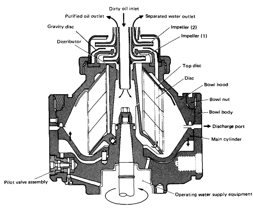
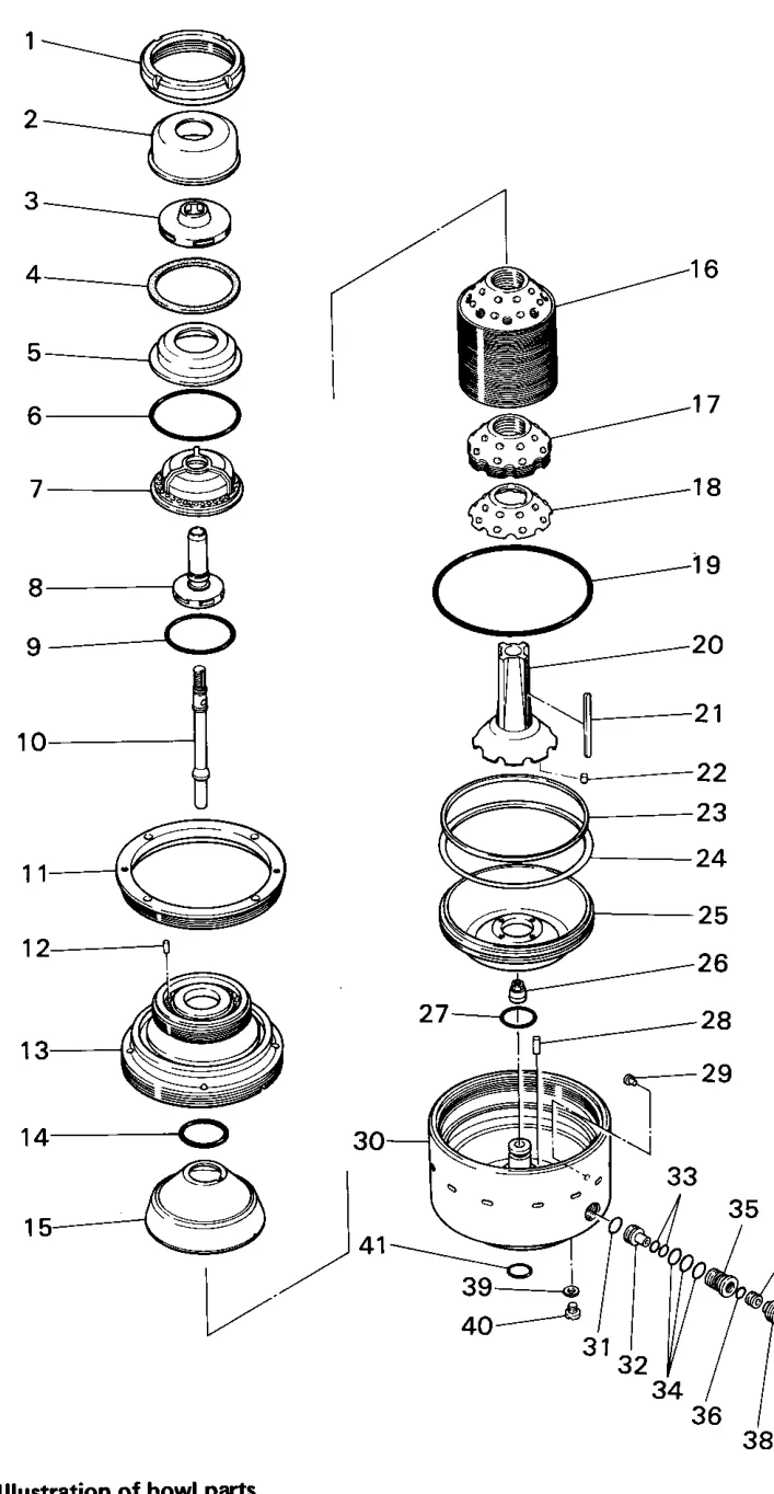
The bowl assembly, part by part
The bowl is a matched set of parts, not a collection of interchangeable ones. Where each part sits is what this chapter is about.
| Part | Position in the assembly |
|---|---|
| Bowl body | Lower rotating container; forms the outer wall and the sludge space |
| Bowl hood | Closes the top of the body; carries the main seal ring seat |
| Bowl nut | Top of the stack of parts; clamps hood to body |
| Distributor cone | Centre of the bowl, below and inside the disc stack |
| Disc stack | Around the distributor, filling the separation chamber |
| Top disc | Caps the stack, immediately under the hood |
| Gravity disc | At the heavy-liquid outlet, above the top disc |
| Sliding bowl bottom | Lower moving wall of the sludge space |
| Outlet impellers | Upper part of the bowl, one per liquid outlet |
| Seals and O-rings | In grooves wherever two chambers or two parts meet |
How the groups sit together
The bowl sits on top of the vertical spindle, which is carried in bearings inside the frame. The worm wheel is fixed to the spindle below the bowl, and the worm shaft is driven by the motor through the friction clutch. The bowl casing surrounds the bowl and the sludge cover sits over it.
Warning: Everything inside the bowl is a balanced, high-speed assembly. Treating any bowl part as an ordinary machine cover — to be forced, substituted or left out — is how purifiers fail.
2. Bowl body, hood and nut
The bowl is the pressure vessel of the machine. Three parts form the closed container that holds the disc stack and the separated liquids: the bowl body, the bowl hood and the bowl nut.
The bowl body
The bowl body is the lower rotating container. It forms the outside wall of the separation chamber and is the final landing surface for separated solids.
- Supports the distributor and the disc assembly.
- Carries the sludge space where solids collect.
- Contains the hydraulic passages and discharge ports for opening and closing.
- Rotates with the spindle and takes the drive torque.
The wall must stay sound and correctly shaped. Corrosion, erosion or impact damage affects bowl strength, sludge capacity, hydraulic sealing and balance at once.
The bowl hood
The hood closes the upper end of the bowl and encloses the disc stack. The main seal ring is fitted beneath it, and the sealing surface there must never be damaged.
A scored, burred or pitted hood seal surface produces internal oil leakage, operating-water leakage, loss of closing pressure and water mixing with oil. A hood is a machined, balanced part — it is never levered or forced with improvised tools.
The bowl nut
The bowl nut clamps the hood onto the body and compresses everything between them. Correct tightening maintains:
- Disc-stack compression
- Top-disc seating
- Bowl-hood seating
- Seal compression
- Internal hydraulic geometry
- Mechanical integrity at full speed
Tightening is done by the maker's specified method and torque. The nut is part of a balanced rotating assembly, not a stationary cover fastener, and an unknown torque or a hammered-up nut is a defect, not a shortcut.
The bowl is a pressure vessel spinning at several thousand rev/min, holding a large amount of stored energy. Every thread, seal face and nut on it is a safety-critical item.
3. The distributor cone
Feed oil arrives at the bowl standing still, while the bowl is turning at several thousand rev/min. If the oil were dumped straight into the disc stack it would meet the rotating stack with a large relative velocity, and the result would be turbulence, a disturbed interface and poor separation.
The distributor cone solves that problem. It is the first internal flow-control part in the machine.
What the distributor does
- Receives dirty oil from the inlet.
- Passes it outward through radial vanes.
- Brings the oil up to bowl speed.
- Delivers it to the outer edge of the disc stack, where separation begins.
- Locates and centres the disc stack in many designs.
Why the acceleration has to happen first
If the oil entered the discs without being accelerated:
- It would experience strong relative motion against the rotating bowl.
- Turbulence would rise.
- The interface would become unstable.
- Separation efficiency would fall.
- Hydraulic and mechanical losses would increase.
Construction points that matter
The distributor carries the disc stack on keys or splines, so its condition decides whether the stack seats truly.
- Vanes and passages clear, not blocked with sludge.
- No erosion of the vane faces.
- No cracks in the cone.
- Keys and splines sound — a disc pressed on at an angle deforms its key groove.
- Correct seating on the bowl body.
The distributor accelerates the feed; it does not separate it. Separation only begins where the oil enters the gaps between the discs.
4. Disc stack and top disc
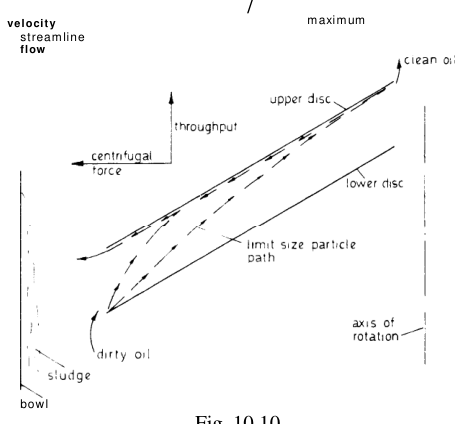
The disc stack is the separation chamber proper. It is a set of thin conical discs stacked closely together, typically about half a millimetre apart, carried on the distributor and capped by the top disc.
The drawing is conceptual. Exact disc profiles and spacing depend on the model.
The forms of disc found in one stack
A stack is not a pile of identical plates. Most makers use several forms, and each has a fixed place.
| Disc form | Where it sits | Why it is there |
|---|---|---|
| Main discs | Bulk of the stack | Establish the closely spaced settling passages |
| Smaller-diameter discs | Lower part of the set on some models | Match the lower internal flow geometry and the transition from the distributor |
| Lowermost disc with distance pieces | Bottom of the set | Set the axial spacing and the lower flow passage |
| Top disc | Top, immediately under the hood | Cap the stack and define the upper liquid regions |
Compression of the stack
The stack must be held in compression so the discs stay in their designed positions while the bowl turns. Compression prevents axial movement, gaps between discs, uneven flow distribution, disc vibration, mechanical rubbing and unbalance.
Disc sets lose elasticity with age. A set that was not in close contact when new settles under nut load and centrifugal force, and a gap opens between the top disc and the stack.
The correction is model-specific and may need the proper spare or compensating disc from the maker's drawing. Too many or too few discs changes stack height, compression, passage geometry and balance — a missing disc is a defect, not a spare left over.
Why disc order matters
Discs differ in diameter, internal holes, external profile, distance pieces, key arrangement and flow openings. If one is placed in the wrong position, feed distribution changes, the lower transition can be blocked, the stack may not compress correctly and the bowl can unbalance.
The top disc
The top disc closes the upper end of the main stack and must be correctly located relative to the hood, the main seal ring, the light-liquid chamber, the heavy-liquid path and the gravity-disc arrangement. It is both a hydraulic boundary and the compression reference for the whole stack.
A gap between the top disc and the stack gives internal bypass flow, poor separation, interface instability, unbalance and outlet contamination.
The stack is a calibrated separation element. Count, order and orientation come from the maker's drawing and must never be guessed or transferred from another model.
5. The gravity disc
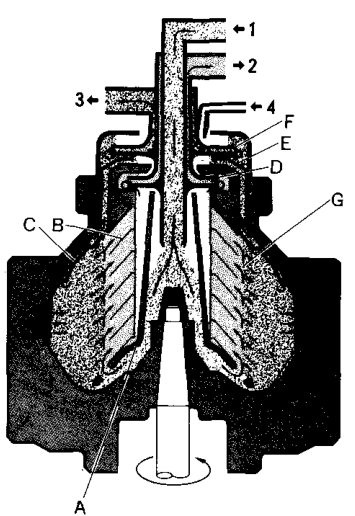
The gravity disc is a ring fitted at the heavy-liquid outlet of the bowl, at the top of the bowl hood. It is not part of the separation stack and it separates nothing. Its job is to set the radius at which water leaves the bowl, and that radius fixes the position of the oil-water interface.
What it does
- Controls the heavy-liquid outlet radius.
- Positions the oil-water interface.
- Balances the light-liquid and heavy-liquid outlet conditions.
- Allows one bowl to treat oils of different density.
Where it sits in the bowl
It sits above the top disc, in the heavy-liquid path. Separated water travels outside the top disc, through the gravity disc, then on to the heavy-liquid impeller and out of the bowl. The gravity disc therefore works in series with the top disc, not with the separation stack.
How the inside diameter shifts the interface
| Gravity disc | Heavy-liquid outlet radius | Interface moves | Result if wrong |
|---|---|---|---|
| Inside diameter larger | Larger | Outward | Interface pushed too far out — oil is lost with the water |
| Inside diameter smaller | Smaller | Inward | Interface pulled into the disc stack — water carries over with the clean oil |
Handling rules: keep discs clean and identified, never mix discs from different models or services, and check the inside diameter against the manual rather than judging by appearance.
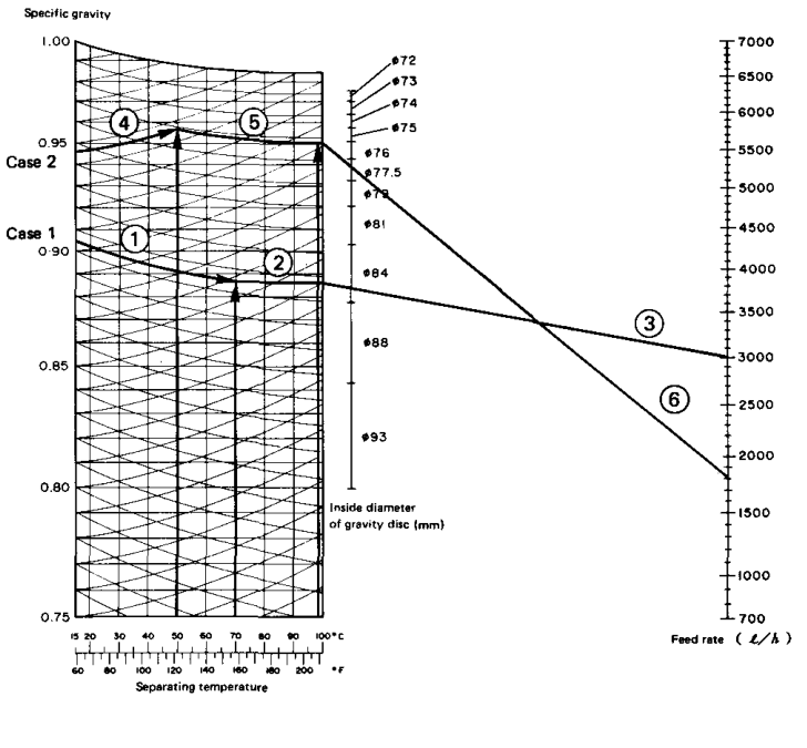
Gravity disc selection depends on the oil density at separating temperature, throughput and viscosity, and it is a procedure of its own — covered in chapter 4. This chapter only establishes what the part is and where it sits.
6. Vertical spindle and bearings
The spindle carries the bowl and transmits torque from the worm wheel to the bowl. It is slender by design, and in service it is meant to flex.
Why the spindle is flexible
A bowl at 6,000-8,000 rev/min can never be made perfectly balanced to the last gram, and the sludge load it carries is never perfectly even. If the spindle were short and rigid, every trace of residual imbalance would be forced into the bearings as a rotating load.
Instead the bowl and spindle assembly is mounted so that it can flex, and it is designed to run above its first critical, or whirling, speed.
- Below the critical speed, during run-up, the assembly passes through a brief period of increased vibration. This is a design condition, not a fault — provided the maker's starting procedure is followed.
- Above the critical speed, the bowl rotates about its own centre of mass. The mass centre becomes the axis, and the flexible spindle lets the bowl find that axis instead of fighting it.
- Vibration therefore falls again as the bowl reaches rated speed. A purifier that runs rough at 2,000 rev/min and smooth at 6,000 rev/min is behaving normally.
Bearings and mounting
- An upper bearing guides the spindle immediately below the bowl.
- A lower bearing carries the drive end of the spindle.
- The bearing housing is mounted flexibly, often on springs or resilient buffers, so the assembly can move radially rather than load the bearings.
- Bearings need the correct lubricant and clearance. A worn or dry bearing destroys the flexibility the whole design depends on.
What a spindle or bearing fault looks like
- Vibration that does not settle as speed rises.
- Vibration that appears only near rated speed.
- Noise from the bearing housing.
- A warm bearing housing.
- A bowl that no longer spins freely by hand, or runs down too quickly.
Warning: Never run a purifier with unexplained vibration in the hope that it will settle. On a machine carrying this much stored energy, a worn spindle or bearing is a safety issue, not an inconvenience.
7. Worm gear and friction clutch
This is the part of the machine that turns a slow electric motor into a very fast bowl — and does it without snatching the bowl up to speed.
Why a step-up drive is needed
A standard marine motor runs at about 1500-1800 rev/min (50-60 Hz). A disc-type purifier bowl runs at roughly 5000-8000 rev/min. The drive must multiply motor speed by four or five times, in a small, quiet, oil-tight casing.
bowl speed = motor speed × gear ratio
For example, a four-pole motor at 1500 rev/min driving a worm ratio of 4:1 gives 6000 rev/min at the bowl.
The drive runs from the electric motor through the friction clutch and horizontal worm shaft to the worm wheel, vertical spindle and bowl. One worm pair provides the step-up and turns the drive through 90 degrees.
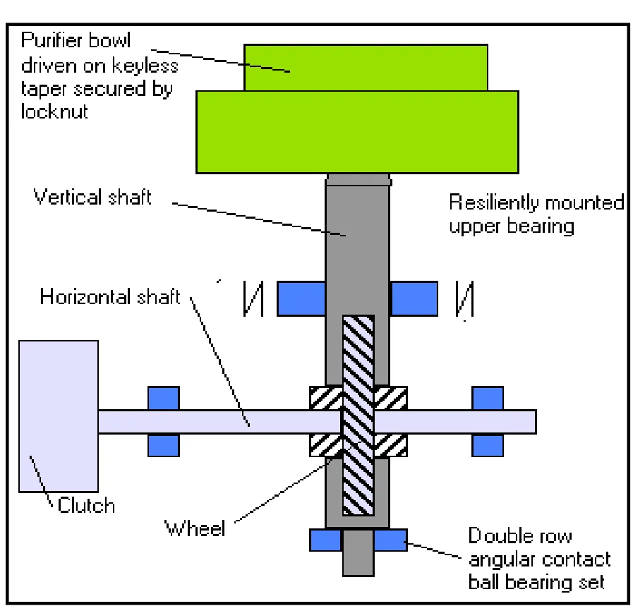
The worm and worm wheel
A worm is a screw-like shaft that meshes with a toothed wheel, the worm wheel. One turn of the worm advances the wheel by a single tooth, which is why a large ratio is obtained in one stage.
- Large ratio in one stage. A single worm pair gives the whole step-up, so no long gear train is needed.
- Compact and quiet. The teeth mesh in sliding contact along the thread, so a worm drive runs smoothly and quietly compared with spur gears at the same ratio.
- Axes at right angles. The worm is horizontal and the worm wheel carries the vertical spindle, so the drive turns neatly through 90 degrees.
- The price is friction. Sliding contact between worm and wheel generates a lot of heat, so efficiency is lower than a spur gear pair and that heat has to be removed.
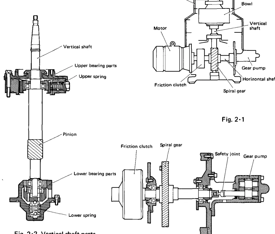
Lubrication and cooling of the worm gear
A worm gear must have continuous oil lubrication. It cannot run dry, and grease alone is not enough.
- The gear case is an oil bath — the worm wheel dips into the oil and carries it to the mesh.
- The oil level must be checked and topped to the maker's mark. Too little oil destroys the mesh; too much causes churning and overheating.
- The oil is cooled, either by an oil cooler in the circuit or by a cooling coil in the sump using the purifier's cooling water.
- Worm-gear oil must be the grade the maker specifies. Ordinary lubricating oil will not carry the sliding load.
- High oil temperature is the first sign of trouble: it means the mesh is losing efficiency, the oil level is wrong, or the clutch is slipping and dumping friction heat into the drive.
The friction clutch
Between the worm shaft and the bowl spindle sits a friction clutch, normally a multiple-disc type. Its whole purpose is to connect the drive to the bowl gradually instead of solidly.
| Purpose of the clutch | Why it matters |
|---|---|
| Slip during run-up | The bowl accelerates smoothly instead of being snatched from rest |
| Limit starting torque | The motor does not see the full inertia of the bowl at the instant of starting |
| Limit starting current | A soft start keeps motor current within limits and avoids tripping the breaker |
| Protect the drive | If the bowl seizes or is jammed, the clutch slips and the worm gear, spindle and motor are spared |
The plates are pressed together by springs and transmit a set torque; above that torque they slip. The slip setting is part of the design and must not be altered to make the bowl come up faster.
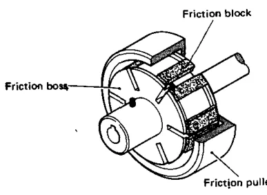
When the clutch slips in service
Worn or contaminated plates, weak springs or an oil-soaked clutch slip below the design torque.
| Symptom | What it tells you |
|---|---|
| Bowl will not reach rated speed | The clutch is slipping under load |
| Run-up takes much longer than normal | Torque transmission is reduced |
| Burning smell near the drive | Friction heat from a slipping clutch |
| Drive oil temperature high | Heat from the clutch inside the gear case |
| Black dust or wear debris in the gear oil | Plate wear |
A slipping clutch is not a speed problem to be forced. Find the cause — worn plates, weak springs or oil contamination — and reset the clutch to the maker's figure.
8. Sliding bowl bottom
A self-cleaning bowl has a moving bottom. It is the only major part of the bowl that changes position in service, and it is what allows sludge to be ejected without dismantling the machine.
What it is
The sliding bowl bottom, called the main cylinder in some manuals, is a hydraulically operated piston that forms the lower wall of the sludge space. It slides a short distance up and down on the bowl body.
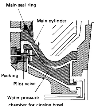
Closed position — normal running
- Operating water pressure holds the bottom hard against the bowl body seal.
- The discharge ports around the bowl periphery are sealed.
- Solids collect against the bowl wall in the sludge space.
- Oil and water follow their normal outlet paths.
Open position — sludge discharge
- Feed is reduced or stopped by the control system.
- The opening-water chamber is pressurised.
- Hydraulic force overcomes the closing force and the bottom drops.
- The discharge ports open and sludge is thrown out at bowl speed.
- The bottom closes again and the liquid seal is re-established.
Construction points that decide whether it works
- Bottom seal rings — worn or hardened rings leak closing water and the bowl cannot stay closed.
- Sliding surfaces — must be clean and free. Sludge or scale makes the bottom stick or tilt.
- Discharge ports — blocked ports leave sludge in the bowl, reduce the separation area and unbalance the bowl.
- Balance of the bottom — an uneven sludge load left by a partial discharge tilts the bottom and causes vibration.
A bowl that will not close, or opens on its own, is a hydraulic and seal problem, not an oil problem. The causes lie in the closing-water supply, the operating nozzle and the bottom seals.
9. Operating water chambers and pilot valves
Operating water is the muscle that moves the bowl bottom. It is clean water at controlled pressure, kept entirely separate from the oil being treated.
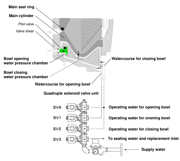
The two chambers
The bowl body contains two annular chambers that oppose each other.
| Chamber | Job |
|---|---|
| Closing-water chamber | Holds the sliding bottom closed against the bowl body during normal running |
| Opening-water chamber | When pressurised, overcomes the closing force and drops the bottom to discharge |
Water reaches the chambers through passages in the bowl body and the spindle. Because the bowl is spinning, water is fed at the centre and travels outward under its own centrifugal pressure.
Why the water must be clean
The passages and nozzles are small. Scale, grit or dirt in the operating water blocks them, and a blocked passage shows up as a bowl that fails to open or fails to close. Operating water is normally taken through a strainer and a reducing valve.
Pilot valves
Pilot valves are small hydraulic valves carried on or around the bowl body. They sense operating-water pressure and route it to the correct chamber at the correct moment.
- They must open and close at the right time in the cycle.
- They must stay free of sludge and scale.
- They must hold their seats — a leaking pilot valve bleeds closing water and lets the bowl open by itself.
The sequence the control system must keep
- Sealing water established.
- Bowl closed and held closed.
- Feed admitted and separation running.
- Discharge initiated — opening water applied.
- Bottom drops, sludge leaves, bottom re-closes.
- Seal restored before feed returns.
Timing is set by the control timer. If the discharge interval is too long for the contamination load, the sludge space fills, separation suffers and the bowl unbalances.
Opening water and closing water come from the same supply. A drop in supply pressure can therefore make the bowl open when it should be closed.
10. Seals, O-rings and tally marks
Inside the bowl, four different fluids sit within a few millimetres of one another: oil, separated water, operating water and the atmosphere inside the frame. Seals are what keep them apart.
| Seal | Where it sits | What it keeps apart |
|---|---|---|
| Main seal ring | Beneath the bowl hood | Bowl interior from the frame |
| Bowl bottom seals | On the sliding bowl bottom | Closing water from the sludge space |
| O-rings | Grooves in body, hood and cylinder | Oil, water and operating water in their own chambers |
| Valve-seat seals | Pilot valves | Operating water from the drain |
| Outlet packing | Light and heavy outlet impellers | Product from leakage to atmosphere |
Installation rules
- Clean the groove and inspect the seating surface — a scratch or a burr defeats a new seal.
- Lubricate only with the maker's approved lubricant.
- Do not twist an O-ring when fitting it.
- Do not pinch or roll a seal during insertion.
- Never reuse a hardened, cut or flattened seal.
- Confirm the seal is fully seated before the parts are closed up.
A seal that has been twisted or pinched looks correct from outside and fails within minutes of start-up.
Tally marks and balance
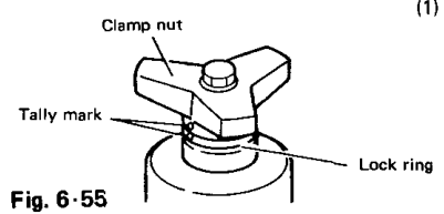
The bowl is dynamically balanced as an assembly. Individual parts — the bowl body, the heavy-liquid chamber and the bowl nut — carry matching tally marks, and those marks must be aligned on assembly.
If the parts are fitted in the wrong angular relationship, the mass distribution changes, vibration rises, the bearings are loaded unevenly and the bowl can rub or fail.
Seal failure symptoms
- Oil leaking from the bowl or frame.
- Water mixing with the clean oil.
- Bowl unable to close, or opening after a long delay.
- Loss of operating-water pressure.
- Sludge pressed into a gasket.
Warning: Tally-mark alignment is a rotating-balance requirement, not a cosmetic detail. A bowl assembled out of alignment can fail.
11. Purifier versus clarifier construction
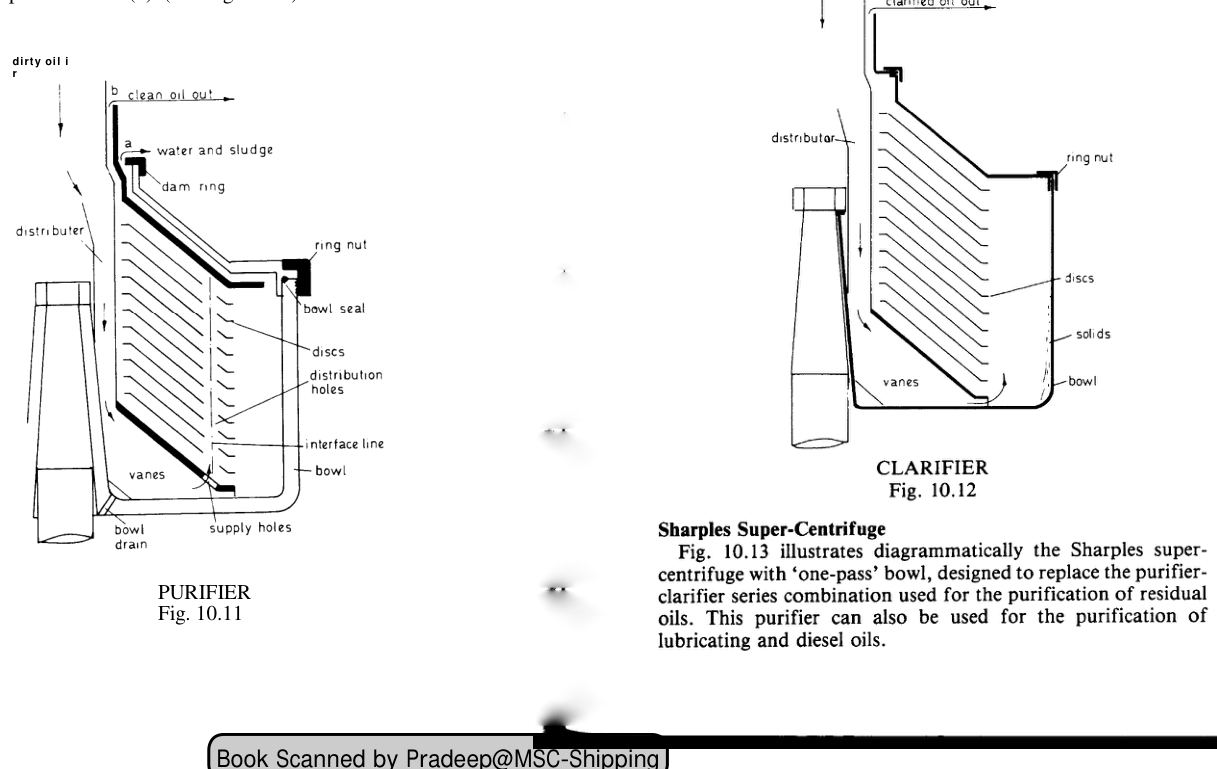
A purifier and a clarifier share the same bowl body, hood, nut, disc stack and sliding bottom. The physical difference is at the top of the bowl, where the two machines diverge.
The physical differences
| Feature | Purifier bowl | Clarifier bowl |
|---|---|---|
| Gravity disc | Fitted, in the heavy-liquid path | Not fitted |
| Heavy-liquid outlet | Fitted — separated water leaves the bowl | Not fitted |
| Sealing water | Supplied to establish the liquid seal before feed | Not supplied in the same way |
| Top disc arrangement | Lets water pass outside it to the gravity disc | Seals the stack against the hood — one liquid region |
| Liquid outlets | Two — clean oil and water | One — clean oil |
| Outlet impellers | Light-liquid and heavy-liquid impellers | Light-liquid impeller only |
Why the top of the bowl differs
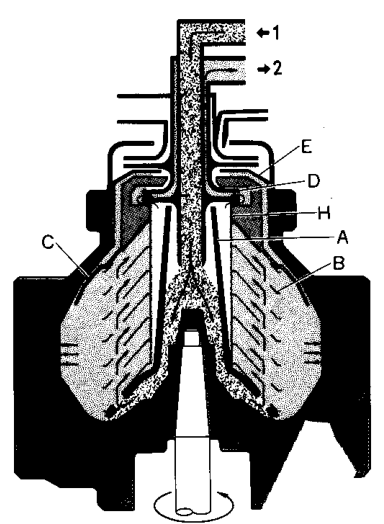
In a purifier, the top disc must allow separated water past it, on its way to the gravity disc and the heavy-liquid outlet. In a clarifier there is no water outlet, so the top disc closes the stack against the bowl hood and the bowl has only one liquid region. Feed enters, solids go to the wall and oil leaves by the single outlet.
Can one machine be changed to the other?
On many models a purifier can be converted to a clarifier by fitting the clarifier top-disc arrangement, blanking the heavy-liquid outlet and disabling the sealing-water supply — and converted back again. This is done with the maker's conversion kit, not improvised in the field, because the internal geometry, outlet parts and control settings must all match.
A clarifier has no water seal to establish and no interface to set, which is why it is simpler to start — but it cannot remove water.
Practise this in the question bank
- Purifier / Clarifier — 19 questions
Found a mistake, or something unclear?
Report it in a few seconds — it goes straight to the editors.
- Purifier Principle: Centrifugal Separation & Stokes' Law
- Purifier Types: Purifier vs Clarifier, Disc vs Tubular
- Purifier Construction: Bowl, Disc Stack and Drive
- Purifier Working: Three-Phase Flow & Gravity Disc
- Purifier Operations: Start-Up, Running & Conditioning
- Purifier Maintenance: Cleaning, Inspection & Overhaul
- Purifier Safety: Emergency Stop, Fire-Fighting & Vibration Response
- Purifier Troubleshooting: Fault Diagnosis and Fixes