

Purifier Working: Three-Phase Flow & Gravity Disc
How a marine purifier works: feed and distributor, laminar flow between discs, the oil, water and solid paths, the e-line outside the disc stack, gravity-disc sizing and desludging.
1. The complete three-phase flow
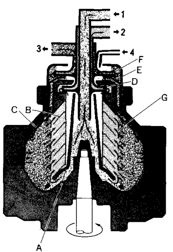
A purifier takes one mixed feed and produces three separate outputs. The whole machine reduces to a single flow map: feed enters once, and oil, water and solids each leave by their own route.
The three phases are:
- Light liquid — the clean oil.
- Heavy liquid — the separated water.
- Solid phase — sludge, rust, catalyst fines and wear particles.
The Mitsubishi manual calls this three-phase liquid-liquid-solid separation. It is not two jobs in sequence: the machine separates water and solids at the same time, continuously.
One rule covers the whole map: oil moves inward, water moves outward, and solids move outward to the bowl wall.
| Phase | Density order | Direction | Leaves by |
|---|---|---|---|
| Oil (light liquid) | Lightest | Inward, toward the axis | Light-liquid outlet |
| Water (heavy liquid) | Intermediate | Outward | Heavy-liquid outlet |
| Solids and sludge | Heaviest | Outward, to the wall | Sludge space, then discharge ports |
Each route is worked through in the sections that follow, and the machine's own bowl diagram names every one of them.
2. Feed entry and the distributor
Feed arrives through the feed-liquid inlet while the bowl is already turning at several thousand rev/min. The oil in the pipe is moving at pipe speed — effectively stationary compared with the bowl.
If that slow-moving oil were released straight into the separation chamber, the relative velocity would be enormous. Turbulence would develop, the phase boundary would be disturbed, separation would fall, and mechanical energy would be wasted.
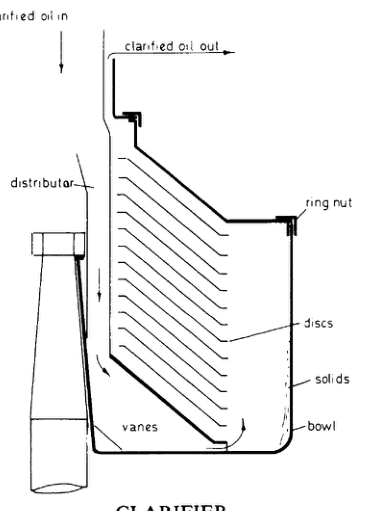
The distributor prevents this. Radial vanes in the distributor pick up the incoming feed and bring it close to bowl speed before releasing it into the separation chamber.
What the distributor does, and does not, do
- It accelerates the feed to near bowl speed.
- It delivers the feed to the outer periphery of the disc stack, not to the centre.
- It protects the flow paths from disturbance.
- It does not separate anything. It prepares the feed for the separation chamber.
A restriction or an incorrect connection at the feed inlet reduces the effective capacity of the machine even when the bowl itself is perfectly healthy. Feed must enter the correct location, at the correct pressure and rate, with no air leakage.
3. Flow between the discs
The disc stack divides the separation chamber into many narrow passages, typically about 0.5 mm apart. This is where the actual separation happens.
Inside a passage:
- Oil follows the liquid flow inward toward the axis.
- Water is thrown outward relative to the oil.
- Solids are thrown outward even more strongly, because they are denser still.
Why the flow must stay laminar
Friction holds the oil almost stationary at each disc surface, and it moves fastest in the middle of the passage.
That velocity profile is what makes the stack work. A particle that reaches a disc surface enters a region of almost zero velocity, and from there centrifugal force can slide it along the disc into the sludge space instead of being swept back into the oil.
If the flow becomes turbulent, particles are mixed back into the stream, water droplets are re-emulsified, and separation efficiency falls.
Water and separated sludge move radially outward along the underside of the conical discs while purified oil moves radially inward over their upper surfaces.
Separation is progressive, not instantaneous. It builds up as the liquid travels through the stack, so the oil leaving the outermost part of the stack is not yet clean.
4. The oil path
Oil is the lightest of the three phases, so it occupies the inner region of the bowl. Its path is entirely inward.
Oil path step by step
- Oil enters with the feed liquid.
- It passes through the distributor.
- It enters the disc stack at the outer region.
- Water and solids move away from it.
- It travels inward between the discs.
- It reaches the light-liquid chamber.
- The light-liquid impeller discharges it.
- Clean oil leaves through the light-liquid outlet.
The light-liquid impeller is a centripetal pump: it uses the energy of the rotating liquid to discharge clean oil continuously against the outlet back-pressure.
What the clean-oil outlet tells you
This outlet is the best single indicator of how the machine is running. Every one of these faults shows up here first:
| Seen at the clean-oil outlet | Likely cause |
|---|---|
| Water carry-over or haze | e-line too far inward, or a disc ID too small |
| Remaining fine solids | Throughput too high, temperature too low, or disc-stack problems |
| Unstable or pulsing flow | Feed, temperature or outlet pressure not steady |
Clean oil at the light-liquid outlet is not proof that separation is perfect. It only proves that the e-line is not far enough inward to push water into the oil side. The water outlet must be checked at the same time.
5. The water path
Water is heavier than oil, so it moves outward and leaves by a different route. The important feature is that it passes outside the top disc and then through the gravity disc.
Water path step by step
- Water enters mixed with the feed oil.
- It passes through the distributor and the disc stack.
- It moves outward relative to the oil.
- It reaches the outer heavy-liquid region.
- It passes outside the top disc.
- It passes through the gravity-disc region.
- The heavy-liquid impeller discharges it.
- Water leaves through the heavy-liquid outlet.
The top disc closes the top of the disc stack and forces the heavy liquid to travel outward past the stack rather than short-circuiting across the top of it. The gravity disc then sets the radius at which that water finally leaves — which is what fixes the interface position, covered in section 7.
| Water outlet condition | What it suggests |
|---|---|
| Mostly water | Normal operation |
| Excessive oil present | Interface or gravity-disc error — e-line too far outward |
| Very little flow | Blockage, low water content in the feed, or a hydraulic problem |
| Sludge present | Discharge or bowl-cleanliness problem |
The water path is not a waste line to be ignored. Oil appearing at the water outlet is the classic sign that the interface has moved too far outward.
6. The solid path and the sludge space
Solid particles are the densest phase and are thrown hard against the bowl wall.
Solid path step by step
- Solids enter with the feed liquid.
- They move through the disc passages.
- Centrifugal force drives them outward.
- They contact the underside of a disc.
- They migrate along the disc toward the outer region.
- They deposit on the bowl wall.
- They form a sludge layer in the sludge space.
- They are removed during manual or automatic discharge.
Why the sludge space must be emptied
Solids accumulate at the bowl periphery throughout operation. Left there too long:
- Bowl capacity falls, because sludge occupies separating volume.
- Disc passages become contaminated.
- Separation efficiency drops and solids are carried back into the liquid stream.
- The bowl becomes unbalanced and vibration rises.
- Discharge ports may block, and mechanical parts can be damaged.
The oil feed is therefore stopped at intervals and the bowl is opened, either manually or automatically, so the solids leave through the discharge ports. After discharge the bowl is closed and the liquid seal is re-established before feed continues.
Separation collapses before the sludge space is visibly full. A partly filled sludge space is enough to raise the limit-size particle and let contamination through, so the discharge interval is set for separation performance, not for the visible sludge level.
7. The interface line (e-line)
The interface, usually called the e-line, is the boundary inside the bowl where oil and water meet. Its radius decides which outlet each liquid reaches, which makes it the single most important setting on the machine.
The rule the syllabus asks for
The e-line must stay outside the disc stack outer periphery.
Why it must be outside the stack and not inside it:
- If the e-line moves inside the disc stack, water enters the disc passages. It is then carried inward with the oil and leaves through the light-liquid outlet — water in the clean oil.
- With the e-line outside the stack, the whole stack is wetted by oil. Water and solids stay in the outer region, where the discs can shed solids outward into the sludge space.
- If the e-line moves too far outward, the oil region grows toward the wall, oil reaches the heavy-liquid path, and oil is lost through the water outlet.
| e-line position | Result |
|---|---|
| Inside the disc stack | Water reaches the oil side — water in the clean oil |
| Just outside the stack periphery | Correct — clean oil and clean water at their own outlets |
| Too far outward | Oil reaches the water side — oil lost through the water outlet |
What moves the e-line
| Factor | Effect on the e-line |
|---|---|
| Gravity-disc inside diameter | The only item the operator changes; sets the heavy-liquid outlet radius directly |
| Oil density at separating temperature | Lower oil density pushes the e-line outward |
| Separating temperature | Changes oil density and viscosity, so it moves the e-line |
| Feed rate | Changes residence time and outlet balance, so it can shift the e-line |
| Sealing-water condition | Poor sealing leaves the interface unable to form correctly |
The e-line is not a fixed ring. It is a hydraulic boundary created by the balance of densities, flow rates and outlet geometry, so it moves whenever one of those changes.
8. Gravity disc sizing
The gravity disc is a replaceable disc in the heavy-liquid outlet path. Its important dimension is the inside diameter (ID), because that sets the radius at which the water leaves, and therefore the e-line position.
- A larger inside diameter moves the e-line outward.
- A smaller inside diameter moves the e-line inward.
Normal method: the maker's nomogram
The inputs are: purifier model, oil type, specific gravity, the temperature at which that specific gravity is known, the separating temperature, and the feed rate. Follow the model-specific nomogram to the gravity-disc inside-diameter scale.
Never use a nomogram from another model, and never select a disc by the oil name alone. The selection needs actual operating data, and the density that matters is the density at the separating temperature, not the figure on the bunker certificate measured at 15°C.
Worked example
Mitsubishi Selfjector condition:
| Input | Value |
|---|---|
| Specific gravity | 0.925 at 15°C |
| Treating temperature | 70°C |
| Feed rate | 3000 L/h |
| Selected disc inside diameter | approximately φ79 mm |
Procedure: locate the curve for specific gravity 0.925; move to the vertical line for 70°C; carry the horizontal construction line across to the reference-temperature side; connect that point to 3000 L/h on the capacity scale; read the inside-diameter range. The result is approximately φ79 mm.
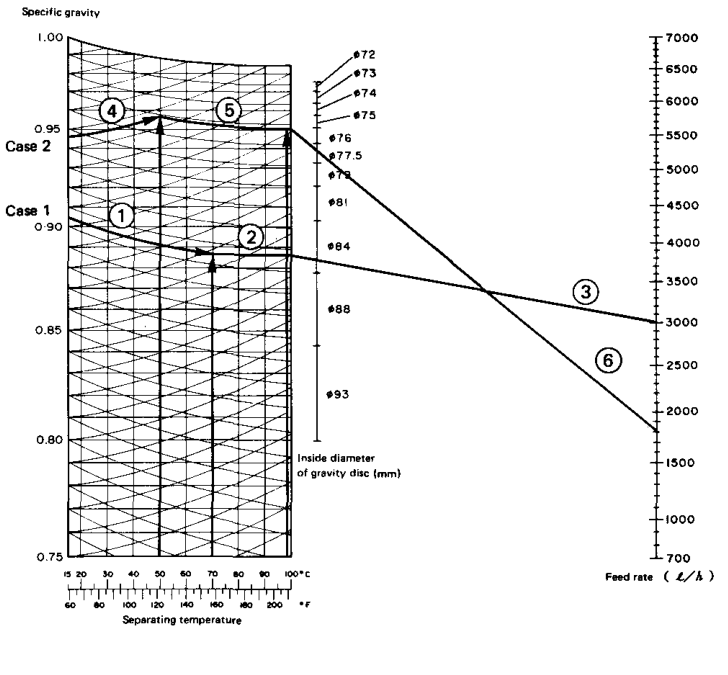
This result applies only to the stated purifier model and operating condition.
No nomogram available: the test-disc method
The exam question asks how to choose a disc without the maker's graph. The answer is a controlled trial, changing one size step at a time and reading the outlets after each run.
- Fit a medium-sized test disc and run the machine with oil and water.
- Watch both outlets, not just the clean-oil outlet.
- If oil comes out of the water outlet, the disc is too large — reduce the inside diameter.
- If water enters the clean oil, the disc is too small — increase the inside diameter.
- Change one size step at a time and repeat the run.
- Stop when the e-line sits just outside the disc stack, with no oil at the water outlet and no water in the clean oil.
| Symptom | Interpretation | Action |
|---|---|---|
| Oil at the water outlet | e-line too far outward — disc ID too large | Reduce inside diameter one size step |
| Water in the clean oil | e-line too far inward — disc ID too small | Increase inside diameter one size step |
| Both outlets clean and stable | e-line correct | Keep the disc; record the condition |
Change one size step only, then re-test. Jumping several sizes at once makes the result impossible to interpret, and every trial must be run at the actual separating temperature and feed rate, because both shift the e-line.
9. Sealing and displacement water
Two water supplies look similar but do different jobs. Sealing water prepares the bowl for feed; displacement water prepares it for discharge.
Sealing water — before feed
Before any oil is admitted, the bowl is filled with water. Sealing water:
- Occupies the heavy-liquid region.
- Prevents oil from escaping through the water outlet.
- Establishes the initial liquid arrangement.
- Helps the e-line form at the correct radius.
Sealing water passes the gravity disc and outside the top disc before accumulating at the bowl periphery. Only then does oil feed begin.
- Bring the bowl to rated speed.
- Supply sealing water.
- Allow water to fill the outer heavy-liquid region.
- Begin the oil feed only after the seal is established.
If sealing water is absent, oil escapes through the water outlet, the e-line may fail to form, separation is unstable and oil is lost during start-up. If sealing water is excessive, water mixes with clean oil and the heavy-liquid load rises.
Displacement water — before discharge
Displacement water is fed into the bowl immediately before sludge discharge. It replaces the oil in the outer region and pushes the oil charge inward, so that when the bowl opens the discharge contains mainly water and sludge and very little oil.
- Reduces oil loss on each discharge.
- Keeps the discharge mostly water and solids, so the sludge outlet stays clear.
- Helps keep the bowl load balanced through the discharge.
| Supply | When it is used | Job |
|---|---|---|
| Sealing water | Before feed | Forms the water seal in the heavy-liquid region so oil cannot escape through the water outlet |
| Displacement water | Immediately before discharge | Replaces oil in the outer region and pushes the oil charge inward, cutting oil loss |
| Replacement water | After discharge, before feed resumes | Restores the liquid volume and the heavy-liquid region so the e-line rebuilds |
Makers do not always use the same name for these supplies: replacement water, sealing water and displacement water are not interchangeable in every manual. Follow the maker's sequence for the installed machine. Wrong water timing shows up as oil at the water outlet or water in the clean oil, and can also trigger a false leakage alarm.
10. Opening and closing water
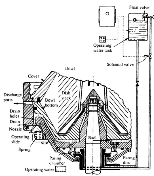
A self-cleaning purifier opens and closes without being dismantled. It does this hydraulically, using operating water from the operating-water tank, reduced in pressure and switched by solenoid valves commanded by the automatic panel. The moving part is the sliding bowl bottom, driven by the main cylinder.
| Supply | Chamber it fills | Effect on the bowl |
|---|---|---|
| Closing water | Closing-bowl pressure chamber | Main cylinder up — bowl closed and held shut |
| Opening water | Opening chamber | Main cylinder down — discharge ports open and sludge leaves |
Closing water
Closing water fills the closing-bowl pressure chamber and pushes the main cylinder upward, pressing the sliding bowl bottom against the main seal ring. In this position the bowl is sealed and the oil, water and solids stay in their intended paths.
Closing water is what holds the bowl shut throughout normal running. If closing pressure is too low, the bowl can leak or open unexpectedly.
Opening water
Opening water is admitted to the opening chamber and overcomes the closing pressure, forcing the main cylinder down. The sliding bowl bottom drops, the discharge ports are exposed, and sludge and water are thrown out.
Opening water must be supplied at the correct pressure for the correct time. Too little or too short leaves sludge behind; too much or too long wastes water, loses oil and shocks the seals. A bowl that closes too early presses solids into the gasket.
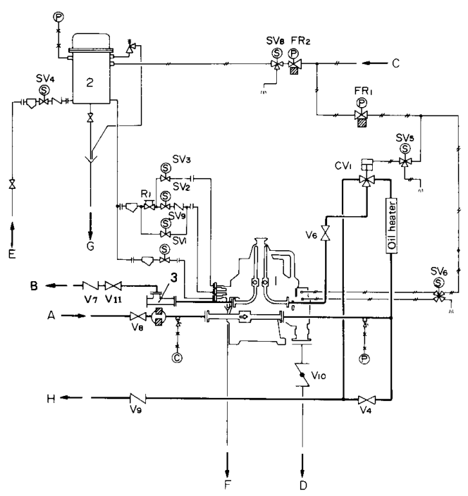
The operating-water solenoid unit controls four separate supplies: opening water, closing water, sealing water and replacement water. Never change operating-water timers or pressure without the maker's tables for that model and water flow rate.
11. Partial and total desludge sequences
The bowl can be emptied in two ways, and the choice is made by the automatic panel according to the oil and the contamination load.
| Feature | Total discharge | Partial discharge |
|---|---|---|
| Bowl contents | Mainly all discharged | Water and some solids discharged; oil charge retained |
| Oil loss | Potentially greater | Normally lower |
| Main purpose | Sludge removal and full clearing | Frequent water and solid removal |
| Re-sealing | Required | Required according to model |
| Bowl washing | May follow for lubricating oil | May be separate or programmed |
Total discharge sequence
- Purifying operation — bowl closed, oil feeding normally.
- Stop or divert the feed; feed must not be flowing when the bowl opens.
- Supply opening water; the main cylinder moves down and the ports open.
- Discharge the bowl contents — water, sludge and contained liquid leave through the ports.
- Supply closing water; the mechanism returns to the sealed position.
- Re-establish the seal with sealing or replacement water, rebuilding the heavy-liquid region and the e-line.
- Resume feed, but only once the bowl is closed and sealed.
Total discharge is used for routine sludge removal at the programmed interval, for a change of oil, and before shutdown. Typical manual examples are 60 to 120 minutes depending on the oil. Lubricating-oil machines may add a bowl-washing step after the total discharge to remove deposits left behind.
| Treated oil | Example discharge interval |
|---|---|
| A heavy fuel oil | 120 minutes |
| C heavy fuel oil | 60 minutes |
| Cross-head engine lubricating oil | 120 minutes |
| Trunk-piston engine lubricating oil | 60 minutes |
These are manual examples, not universal settings. The interval depends on oil type, solids and water content, feed rate, purifier size and engine operation.
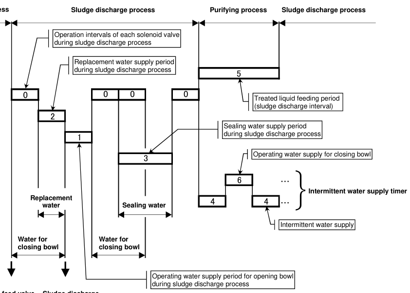
Partial discharge sequence
- The bowl stays mainly filled and the oil charge is retained.
- Opening water is admitted through the opening-water path.
- The mechanism moves just enough to release the separated water and some solids.
- The bowl is closed again and the liquid arrangement is restored.
Partial discharge is used when the feed carries a lot of water and frequent water removal is needed, because it loses far less oil per cycle than a total discharge.
In both sequences the feed must be stopped or diverted before the bowl opens. Opening a bowl with feed still flowing throws oil straight to the sludge outlet and wastes the whole charge.
12. Water ingress detection and feedback
Modern machines close the control loop with detectors. Instead of discharging on a fixed timer alone, the panel can discharge or alarm on what the machine is actually doing — water loading, seal condition and whether the sludge actually left.
The detectors
| Detector | What it watches | Signal to the panel |
|---|---|---|
| Leakage monitor | Pressure at the light-liquid outlet | A pressure drop indicates leakage from the bowl |
| Discharge detector | Horizontal-shaft speed (proximity sensor) | A brief speed dip confirms that discharge occurred |
| Water detector | Water arriving at an unexpected outlet | Indicates water carry-over or a wrong water sequence |
| Pressure and temperature transducers | Feed and outlet conditions | Used to hold the operating point steady |
The leakage monitor works on the pressure at the light-liquid outlet. A pressure drop points to a bowl that is not fully closed, a damaged main seal ring, operating-water leakage, or incorrect outlet pressure. The outlet pressure must be adjusted to the preset level before the monitor can be relied on, because feed-rate and temperature fluctuations also affect its output.
The discharge detector uses a proximity sensor on the horizontal shaft. Discharge creates a temporary load change, so the shaft speed dips briefly to a preset level. If the expected dip does not occur, the panel flags no discharge, incomplete discharge, a bowl that failed to open, a sensor fault or an incorrect detector setting.
The water detector identifies water arriving where it should not be, which usually means an incorrect interface condition, a leakage path, a fault in bowl closure or an incorrect water sequence.
Multi-Monitor
The Multi-Monitor (MM-1, MM-2 and MM-3 variants depending on model) collects the sensor signals into one unit and drives the display, the alarm and a control-panel signal.
How the loop closes
- The detectors measure pressure, speed and water arrival continuously.
- The Multi-Monitor compares each signal with its set point.
- If the reading is outside the band, the panel acts on the sequence — for example, triggering a discharge when water loading rises — or raises an alarm.
- After the action, the detectors confirm whether the machine actually responded.
On Alfa Laval ALCAP and Mitsubishi Selfjector machines the water detector or transducer can trigger a discharge when water loading rises, so the interval follows the oil instead of a fixed clock. This is the difference between a timer that assumes a clean fuel and a loop that responds to the oil actually being treated.
Confirming that the loop is working
Signs that a discharge actually happened, to be read together rather than one at a time:
- A short discharge sound.
- A current increase or change on the starter.
- A discharge-detector response.
- Water or sludge flowing to the drain.
- Pressure returning to normal after discharge.
- A normal bowl-closing response.
A lamp or a detector output alone does not prove that a hydraulic action happened. Confirm with current change, discharge sound, pressure movement, speed movement and the actual outlet condition. Never disable a detector without following the maker's documented procedure.
Found a mistake, or something unclear?
Report it in a few seconds — it goes straight to the editors.
- Purifier Principle: Centrifugal Separation & Stokes' Law
- Purifier Types: Purifier vs Clarifier, Disc vs Tubular
- Purifier Construction: Bowl, Disc Stack and Drive
- Purifier Working: Three-Phase Flow & Gravity Disc
- Purifier Operations: Start-Up, Running & Conditioning
- Purifier Maintenance: Cleaning, Inspection & Overhaul
- Purifier Safety: Emergency Stop, Fire-Fighting & Vibration Response
- Purifier Troubleshooting: Fault Diagnosis and Fixes