

Air Compressor Operations — Lubrication, Drains & Running
Splash and forced lubrication, compressor oil specs, oil carryover mechanics past rings and packing, valve carbonization and explosion link, separator
1. Splash vs Forced Pressure Lubrication Systems
Marine reciprocating air compressors utilize either splash lubrication (common in small to medium trunk-piston auxiliary compressors) or forced pressure feed lubrication (standard in larger multi-stage machines and heavy-duty compressors).
1. Splash Lubrication Dynamics
In splash-lubricated compressors, a profiled dipper or scoop integrated into the bottom of each connecting rod bearing cap dips into the crankcase oil reservoir with every revolution. At 1,200 to 1,800 RPM, this impact creates a vigorous, atomized oil mist that drenches the crankcase interior:
- Cylinder Wall Wetted Area: The atomized fog coats the exposed lower cylinder liner walls. On the subsequent upward stroke, the piston rings spread a controlled thin boundary film over the swept area.
- Critical Sump Level Dependency: If the crankcase oil level is too high, the connecting rod plunges deeply into bulk oil. This causes churning, excessive fluid friction, severe oil foaming, rapid temperature rise, and massive oil carryover into the compression chamber. If too low, oil mist density drops, leading to boundary lubrication breakdown, gudgeon pin seizure, and liner scuffing.
2. Forced Pressure-Feed Systems
Higher-capacity marine compressors use a positive-displacement gear pump driven directly from the crankshaft end:
- Circulation Loop: Oil is drawn from the sump through a suction strainer, discharged through an external cartridge filter (typically 25-micron rating) and cooler, and led into the main bearing journals.
- Crankshaft Drilling: Internal diagonal drillings convey pressurized oil from the main journals to the crankpins, and upward through the connecting rod rifle-drilling to the small-end gudgeon pin bush.
- Safety Trip: Forced systems are equipped with a low lube oil pressure trip switch (typically set to stop the compressor motor if oil pressure drops below 1.5 to 2.0 bar).
2. Marine Compressor Lubricant Specifications & Chemistry
Unlike diesel engine crankcase oils, air compressor cylinder lubricants face a unique chemical hazard: direct exposure to compressed air at elevated temperatures (up to 160°C–180°C) with elevated oxygen partial pressures (up to 30 bar). Under these conditions, petroleum hydrocarbons are prone to severe thermal oxidation, polymerization, and volatile cracking.
| Property | Standard Marine Requirement | Engineering Significance |
|---|---|---|
| Viscosity Grade | ISO VG 68 or ISO VG 100 | Must maintain sufficient hydrodynamic film thickness (≥ 2 μm) at 120°C without causing excessive viscous drag on piston rings. |
| Flash Point (Closed Cup) | > 220°C (Open Cup > 240°C) | Provides a mandatory safety margin above maximum stage discharge temperatures (normally tripped at 93°C–100°C) to prevent vapor-phase ignition. |
| Auto-Ignition Temperature | > 350°C to 400°C | Prevents spontaneous compression ignition of oil aerosol droplets under sudden pressure waves. |
| Conradson Carbon Residue (CCR) | < 0.05% (DIN 51506 VDL grade) | Minimizes carbonaceous crust formation on valve plates. High-carbon oils form hard lacquer that causes valves to leak. |
| Demulsibility | Rapid water separation (< 15 min) | Moisture condensed in the intercooler must separate cleanly from the oil rather than forming an acidic, emulsified mayonnaise sludge. |
| Base Oil Type | Synthetic (PAO / Polyol Ester) or Hydrocracked Group II/III | Synthetic base oils resist oxidation up to 4 times longer than conventional mineral oils and leave soft, non-sticking carbon residues upon thermal cracking. |
Warning — Chief Engineer Oral Rule: Never use motor engine lubricating oil in an air compressor! Motor oil contains detergent-dispersant organometallic additives (calcium and magnesium sulfonates) that retain moisture and form ash deposits under high heat. When exposed to hot air, these additives catalyze carbon formation, creating hard abrasive clinkers on valve seats that cause valve leakage and spark explosions.
3. Oil Carryover Mechanics: The Ring Pumping Phenomenon
Oil carryover refers to lubricating oil migrating past the piston assembly into the compressed air stream. Even in a well-maintained compressor, a minute quantity of oil aerosol is normal. However, excessive carryover is extremely destructive.
Primary Causes of High Oil Carryover
- Worn Ring Grooves (Excessive Axial Play): When piston groove axial clearance exceeds maker tolerance (e.g., > 0.12 mm), the piston ring acts like a piston pump valve, drawing oil into the clearance on the downstroke and squirting it into the chamber on the upstroke.
- Clogged Scraper Ring Drain Holes: The radial return holes drilled through the piston skirt behind the scraper ring allow wiped oil to drain into the crankcase. When these become plugged with baked carbon, oil has no escape route and is forced upward.
- High Crankcase Oil Level: Overfilling the sump submerges crank webs or dippers excessively, overwhelming the oil scraper ring's wiping capability.
- Cylinder Glazing & Ovality: Mirror-polished liners or bore ovality prevent ring face contact, letting oil slip past ring gaps.
4. Coalescing Filtration, Crankcase Breathers & Shipboard Routines
To eliminate oil carryover before compressed air enters the ship's distribution network and air bottles, specialized mechanical and filtration safeguards are installed.
Shipboard Maintenance Checklist
- Daily Watchkeeping: Check crankcase oil level when stopped; verify forced lube oil pressure (2.0–3.5 bar) during running; feel discharge line temperatures for abnormal overheating.
- 250 Hours Routine: Drain water and oil sludge from moisture separators; clean suction air filter element (restricted suction creates higher vacuum, increasing oil pumping past rings).
- 1,000 Hours Routine: Inspect and clean suction and delivery valves; decarbonize valve plates using approved solvent; replace damaged valve springs; inspect breather wire gauze.
- 4,000 Hours Major Overhaul: Measure cylinder liner bore wear and ovality; renew piston rings and oil scraper ring; inspect piston ring groove vertical clearance with feeler gauges; renew crankcase lube oil charge.
5. Moisture Condensation & Centrifugal Separators
Atmospheric ambient air contains substantial water vapor (humidity). When this air is compressed from 1 bar to 30 bar, its total pressure increases 30-fold, but its saturated vapor pressure is strictly dictated by temperature. Cooling the compressed air causes instantaneous saturation, generating large quantities of liquid water.
Catastrophic Effects of Moisture Separator Carryover
If the moisture separator fills with condensate due to a choked or inoperative auto-drain valve, water is carried over into the high-pressure stage with devastating consequences:
- Hydrodynamic Hydraulic Lock: Water is incompressible. If liquid fills the clearance volume between the piston crown and cylinder head, immense peak pressures shatter concentric valve plates, fracture cylinder head studs, or bend the connecting rod.
- Lubricant Film Washing: Liquid water washes the thin hydrodynamic oil film completely off the cylinder liner walls, resulting in dry metal-to-metal contact, rapid ring scuffing, and piston seizure.
- Acidic Corrosion: Dissolved sulfur oxides and moisture form dilute acids that aggressively pit the valve seating faces and cylinder walls.
6. Automatic Drain Valves & Shipboard Operational Checks
Modern marine air compressors utilize two primary types of automatic drain systems to discharge accumulated condensate:
1. Pneumatic Unloader-Operated Drain Valves
During start-up and shutdown, an unloader solenoid valve vents the cooler separator sumps to atmosphere. This serves a dual purpose:
- Unloaded Starting: Eliminates backpressure on the electric motor, preventing heavy inrush starting currents.
- Purge Blast: The sudden venting causes a violent blast of air that ejects all collected water and oil sludge out of the separator bowls.
2. Electronic Solenoid Timer Drain Valves
While running, a programmable electronic timer energizes an electric solenoid drain valve cyclically: typically opening for 3 to 5 seconds every 15 to 20 minutes.
Watchkeeping Routine: Every watch, the duty engineer must manually open the bypass drain cock on every intercooler and aftercooler separator to verify that dry air emerges. If a heavy, continuous stream of water discharges, the automatic timer or solenoid valve has failed in the closed position.
7. Capacity control
Demand may vary from full capacity to nearly zero.
Capacity can be controlled by:
- Start-stop control
- Bypass or blow-off control
- Suction-valve unloading
- Clearance pockets
- Variable speed
- Cylinder unloaders
- Multiple compressors in parallel
A control method must limit both:
- Capacity.
- Power or driver load.
The compressor reference notes that fixed-speed machines require a method other than speed change to alter capacity and that control may be required to prevent excessive horsepower.
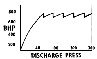
8. Start-stop control
The compressor runs until receiver pressure reaches its upper set point, then stops.
Advantages:
- Low unloaded running power
- Simple operation
- Useful for intermittent demand
Limitations:
- Frequent starts
- Motor heating
- Mechanical transients
- Pressure fluctuation
- Reduced suitability for continuous demand
The motor must normally start unloaded to limit starting current and mechanical stress.
9. Suction-valve unloading
An unloader holds suction valves open during part of the cycle.
The piston then moves gas without completing normal compression on that end.
Capacity steps may include:
- 0%
- 50%
- 75%
- 100%
Advantages:
- Reduces useful capacity
- Can reduce compression power
- Supports automatic pressure control
The unloader must be correctly timed and lubricated.
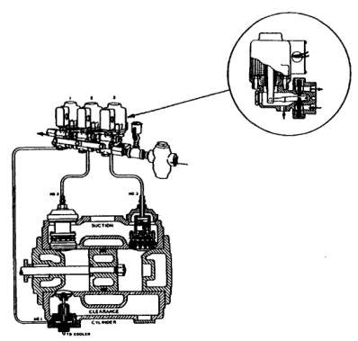
10. Clearance-pocket control
Opening a clearance pocket increases cylinder clearance.
The trapped gas re-expands through more volume before suction begins.
Capacity falls while the compressor may continue rotating.
This can be more energy-efficient than bypassing discharge gas, but the actual power reduction depends on compressor design and pressure ratio.
11. Capacity-control power comparison
The indexed compressor example compares different control steps at changing load conditions and shows that finer control can reduce power consumption in a variable-demand plant.
The practical principle is:
Match delivered capacity to demand with the least unnecessary compression and blow-off.
A compressor that spends long periods unloading or bypassing may have acceptable pressure control but poor specific energy.
12. Capacity-control example
A plant requires 60% of compressor full capacity for most of its operating time.
Poor control
The compressor produces 100% and vents or bypasses 40%.
Better control
The compressor unloads or uses clearance control to produce near 60%.
The second arrangement reduces useful compression of unwanted gas, subject to the control method’s own losses.
The correct choice depends on:
- Compressor type
- Minimum stable load
- Motor behaviour
- Pressure fluctuations
- Start frequency
- Control response
- Safety requirements
13. Performance-test procedure
A useful compressor performance test records:
Process conditions
- Suction pressure
- Discharge pressure
- Interstage pressures
- Suction temperature
- Stage discharge temperatures
- Cooling-water temperatures
- Cooling-water flow
Machine conditions
- Speed
- Load state
- Unloader position
- Clearance-pocket position
- Valve temperatures
- Vibration
- Lubricating-oil pressure and temperature
Output and input
- Flow on a defined basis
- Motor voltage
- Motor current
- Power factor
- Electrical kW
- Receiver pressure-rise time
- Condensate quantity
Hold conditions steady long enough to obtain representative data.
Practise this in the question bank
- Engine Room Auxiliaries (MEP) — 24 questions
Found a mistake, or something unclear?
Report it in a few seconds — it goes straight to the editors.
- Air Compressor Principle, Thermodynamics & Multistage Advantages
- Air Compressor Types & Classification
- Air Compressor Construction — Pistons, Rings, Valves & Running Gear
- Air Compressor Working — Cycle, Volumetric Efficiency, Coolers & Capacity
- Air Compressor Operations — Lubrication, Drains & Running
- Air Compressor Maintenance — Lapping, Clearances & Overhaul
- Air Compressor Safety — Relief Devices, Receivers & SOLAS
- Air Compressor Troubleshooting — Interstage Pressure & Fault Finding