
Overhauling, Inspection, and Repair
A survey is not a search for damage — it is a structured comparison between the condition found and the condition it should be in.
Key Principles at a Glance 8 points
- A survey that produces a repair but no record loses the trend information that would have predicted the repair — recording condition is the most neglected and most valuable objective.
- Isolation is the most dangerous part: isolate fuel, steam, feedwater, blowdown, dosing, sampling and electrical supplies, and fit blanks where a single valve is the only barrier.
- Prove zero pressure at a genuinely representative point — do not rely on a closed valve, a possibly faulty gauge, or the absence of noise.
- A boiler is a confined space: test the atmosphere, ventilate, light it, provide rescue arrangements, and keep an attendant outside at all times.
- The location of the damage is evidence about the mechanism — widespread pitting means oxygen, damage under deposits means concentration effects, damage on the hottest tubes means scale insulation.
- One isolated tube failure usually has a local cause; multiple failures in the same region usually have a systematic cause.
- Excess plugging overloads the remaining tubes and reduces circulation in the surrounding region, which can cause further failures — never exceed the permitted number or pattern.
- A hydraulic test proves tightness, not soundness — it is not a substitute for inspection, and it must be done with air excluded.
1. What an overhaul is for
A boiler survey is not a search for damage. It is a structured comparison between the boiler's present condition and the condition it should be in. The purpose is to find the faults that have not failed yet, while there is still time to plan the repair.
The objectives:
- Confirm the pressure parts are sound — drums, headers, tubes, stays, and welded and expanded joints.
- Remove deposits — scale, sludge, soot, and corrosion products that reduce heat transfer and hide further damage.
- Restore mountings, controls, and protections to correct condition, and prove them.
- Renew worn or damaged parts with the correct spares.
- Prove the boiler is fit for further service, by test and inspection.
- Record the condition in enough detail that the next survey can be compared against it.
The last objective is the most often neglected and the most valuable. A survey that produces a repair but no record loses the trend information that would have predicted the repair.
2. Preparation and isolation
2.1 Why isolation is the most dangerous part
A boiler being opened is a vessel that has been at pressure and temperature, connected to live systems, and containing stored energy in the water, the metal, and the refractory. Every one of those connections must be broken in a controlled order.
2.2 Isolation
- Shut the fuel supply and lock or tag the quick-closing valve.
- Isolate steam — the main and auxiliary stop valves, and any connection through which steam could enter.
- Isolate feedwater — the feed line valve, including the standby feed path, which is easily forgotten.
- Isolate blowdown — surface and bottom blowdown valves. These connect directly to the sea or to a blowdown tank, and a valve left open creates a route for water to enter or for the boiler to drain unexpectedly.
- Isolate chemical dosing — the dosing line, so the boiler cannot be dosed while people are inside.
- Isolate sampling connections — these are small but they connect to the hot boiler water.
- Isolate electrical supplies to fans, burners, actuators, indication, and control. Lock and tag.
- Fit blanks or spades where the isolation is by valve alone and the consequence of leakage is serious. A single closed valve is not proof of isolation.
2.3 Proving isolation
- Prove zero pressure at a point that is genuinely representative. Do not rely on a closed valve, a gauge that may be faulty, or the absence of noise.
- Open drains and vents and confirm they are clear, not blocked or valved closed somewhere downstream.
- Allow the boiler to cool naturally. Force cooling — dumping water, cold air draughting, or water spray on the outside — produces thermal stress and can crack plates or refractory that would otherwise have been sound.
- Drain the boiler and confirm that the water is leaving, not held by a blockage or a closed downstream valve.
2.4 Entry
A boiler is a confined space. The entry procedure is not optional and not negotiable.
- Follow the ship's confined space entry requirements and the permit system.
- Test the atmosphere for oxygen content and for flammable and toxic gas. A boiler that has been steaming, or that has held fuel or combustion products, will have a different atmosphere from outside air.
- Ventilate the space, and continue ventilating while work is in progress.
- Provide adequate lighting — including emergency lighting if the space is deep or complex.
- Provide rescue arrangements and a means of communication with the attendant.
- Keep an attendant outside at all times who maintains communication and who knows what to do if the person inside does not respond.
- Use the correct PPE, and make sure it fits and is in good condition.
- Test the atmosphere again if work stops for a break, or if anything changes — for example, if welding or burning is taking place, or if a connection is broken elsewhere.
A person who enters an unprepared boiler space is at risk from oxygen deficiency, toxic gas, and the loss of consciousness that follows both — often without any warning that would let them leave.
3. Internal inspection
3.1 What you are looking for
Inspection is a comparison and a pattern-finding exercise, not simply a search for broken parts.
Scale and sludge
Note the quantity, the location, and the character. Scale that is hard and crystalline on the hottest tubes indicates calcium sulphate or silicate; porous carbonate scale indicates temporary hardness; a soft sludge that can be washed away indicates an effective precipitate treatment but inadequate bottom blowdown.
Pitting
Note depth, distribution, and whether the pits are isolated or widespread. Isolated deep pits suggest oxygen attack at a specific location; widespread shallow pitting suggests general oxygen ingress.
Grooving
A localised line of corrosion along a joint, tube plate edge, or riveted seam. Common at steam-water interfaces and at areas of flexing.
Cracking
Look particularly at welds and their heat-affected zones; around tube expansions and tube ends; at stay and stay-tube connections; at nozzle and manhole openings where stress concentrates; and in areas of known stress concentration such as sharp-radius sections and the ogee ring.
Bulging and distortion
Indicates local overheating from scale, from poor circulation, or from low water.
Erosion and thinning
Where flow velocity is high, at tube ends, at bends, and at any restriction.
Overheating marks
Discolouration, oxide scale, or a granular, overheated appearance on the metal surface. Note the location relative to the burner and the gas flow.
Leak paths
Water marks, salt deposits, rust staining, and clean streaks that show where water has run.
Deposits under which corrosion is developing
Where a deposit has been removed, inspect the surface beneath it. Crevice conditions under a deposit are where the most serious corrosion occurs.
Internal fittings and tube ends
Separators, baffles, driers, and their fixings — a loose or damaged separator produces carryover even when the chemistry is correct. Also expansions, welds, and the condition of the tube plate ligament between the holes.
3.2 Where deposits and damage collect
| Location | Why damage collects there |
|---|---|
| Bottom of the shell or drum | Low velocity lets sludge settle |
| Under the furnace, around the ogee ring | Narrow water space, limited circulation, deposits can build and cause overheating |
| Tube plates and tube ends | Local flow disturbance and crevices at the expansions |
| Support plates | Water stagnation in the gaps and crevices around the tube |
| Lower headers of water walls | Settling point for sludge |
| Crevices and joints generally | Restricted flow lets aggressive chemistry concentrate |
| Areas of highest heat flux | Deposits form fastest; overheating occurs first |
The location of the damage is evidence about the mechanism. Widespread pitting points to oxygen in the water. Damage concentrated under deposits points to concentration effects. Damage on the hottest tubes points to scale insulation. Damage at a specific mechanical feature points to a design or operational stress.
4. Tube inspection, leak finding, and repair
4.1 Inspection
- Prove the tubes are clear internally, particularly where a blockage would prevent circulation. A blocked tube overheats.
- Inspect the bores where access permits, using a bore light or an introscope, for scale, corrosion, and blockage.
- Check for bulging and ovality by measuring, not by eye, where a tube is suspect.
- Look for overheating discolouration — a change in the colour and texture of the metal shows the temperature it has reached.
- Check expansions and welds for cracks and leaks.
- Examine the pattern. One isolated failure usually has a local cause — a blocked tube, a mechanical defect, a specific deposit. Multiple failures in the same region usually have a systematic cause — treatment, circulation, or operation.
4.2 Finding the leak
Where a leak is not obvious:
Look for the marks. Water marks, salts, rust staining, and clean runs on the metal show the path the water took.
Use a hydraulic test to bring the boiler up to test pressure and look for weeping at the suspected area. This reveals leaks that are invisible when cold and dry.
Inspect adjacent tubes. The mechanism that caused one failure is usually active on its neighbours.
Use an introscope or borescope to look into tubes and into spaces that cannot be seen directly.
Check the gas side for the corresponding leak signature, which is often a clean streak through the soot deposit.
4.3 Repair methods
Plugging
- Used where the boiler maker's rules allow, and only within the permitted limit.
- A tapered plug is driven into each end of the failed tube.
- Plugged tubes lose heating surface and take part of the circulation path out of service. Excess plugging overloads the remaining tubes and reduces the circulation in the surrounding region, which can cause further failures.
- Never plug beyond the permitted number or beyond the permitted pattern.
Tube replacement
- Full replacement of a tube, or replacement of a section where the design allows.
- Correct material is essential — the tube material is specified for the temperature, pressure, and gas-side conditions of its location.
- Welding procedure, welder qualification, and post-weld treatment must meet the specification.
- Expanded tube ends must be expanded to the correct degree and checked for leak tightness.
- The tube must be proven clear of debris and weld spatter after fitting.
Membrane wall repair
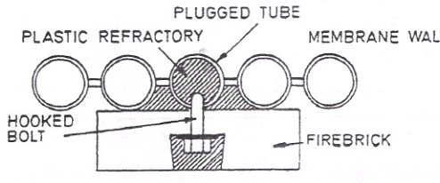
The figure shows the two practical repair methods where a membrane-wall tube fails: plugging the failed tube, and using a hooked bolt arrangement to retain the repaired section. Membrane walls are welded to the drums and headers to form a gas-tight water-cooled wall, so a repair has to restore both the pressure boundary and the wall's structural and gas-tight continuity.
Points that matter for a membrane wall repair:
- The membrane between the tubes carries structural and thermal load, and the repair has to restore it.
- Welding must not distort the panel; distortion closes the tube pitch and can crack adjacent membranes.
- The repaired area must be checked for gas tightness as well as pressure tightness.
- Access is usually restricted, so the repair is planned and prepared in advance rather than improvised.
4.4 After the repair
- Confirm the correct material and welding procedure were used.
- Confirm tubes are clear of debris and spatter.
- Confirm all plugs and fittings are secure.
- Pressure test.
- Record the repair on the tube map — which tube, which method, and when. The tube map is the record that shows how much heating surface has been lost and where.
5. External inspection
5.1 The structure
- Casing, insulation, and cladding — condition, damage, and evidence of hot spots.
- Corrosion under the insulation — particularly around mountings, manholes, handholes, drains, and areas of previous leakage.
- Supports, saddles, and foundations — sound, correctly seated, and free of corrosion.
- Expansion arrangements — slides, rollers, and guides free to move. A seized support transfers expansion loads into the boiler and its connected pipework.
- Holding-down arrangements — correct and tight where required, free where movement is required.
5.2 The equipment
- Fuel line, quick-closing valve, filters, heater, flexible connections. Check for leakage, corrosion, and support condition.
- Burner carrier, register, and quarl. Check for distortion, erosion, and correct alignment.
- Fans, bearings, couplings, dampers, actuators. Check bearings for wear and lubrication, dampers for free travel and correct position feedback, and linkages for slack or wear.
- Uptake, stack, and access doors. Check for corrosion, distortion, and hot spots, which indicate gas leakage.
- Soot blowers. Check the lances for straightness and erosion, the nozzles for blockage and wear, and the wall boxes for gas leakage and cooling air condition.
- Mountings. Safety valves, gauge glasses, gauge connections, and all their fittings. A leaking mounting is the origin of the external corrosion that spreads around it.
- Pipework connections and their supports, so that expansion loads are not imposed on the boiler nozzles.
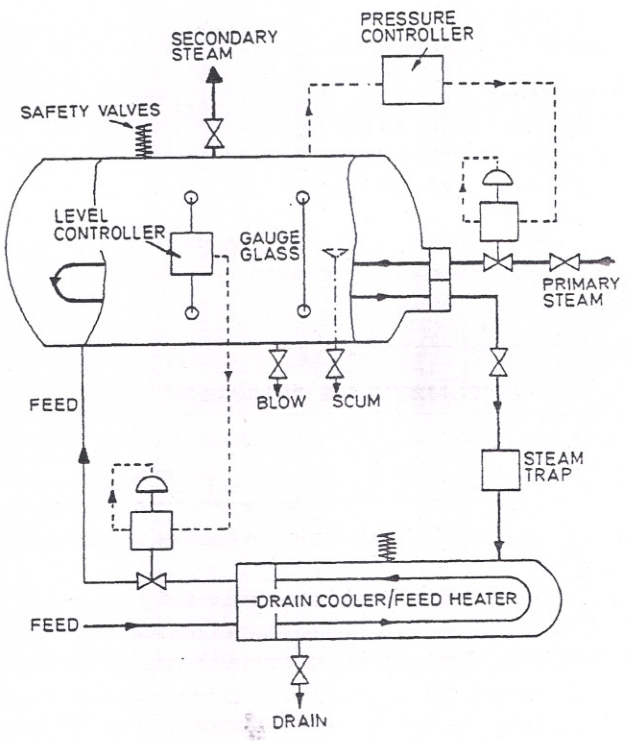
6. Overhauling the mountings and fittings
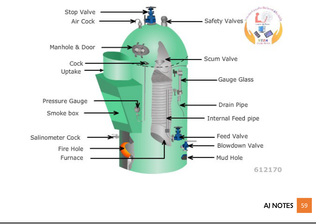
Overhaul the mountings as a set, not as isolated valves: safety valves, water level indicators, water level controller, alarms and cut-out assembly, remote transmitter, main steam outlet, feed inlet and blowdown connections. A mounting left unopened because it "looked all right" is the one that fails first after the overhaul.
6.1 Safety valves
Dismantling and inspection:
Remove the cap, easing gear, and hood, noting the arrangement so it can be reassembled correctly.
Dismantle the valve and clean all parts.
Inspect the valve seat and disc for erosion, wire drawing, pitting, and incorrect contact pattern.
Inspect the spindle for straightness, wear at the guide, and scoring.
Inspect the spring for corrosion, cracks, and loss of free length. A weak or corroded spring changes the set pressure.
Inspect the floating ring, its clearances, and the steam passage to the underside of the spring carrier.
Inspect the compression nut, spring carriers, and all adjustment arrangements.
Renew damaged, corroded, or distorted parts with correct spares. Do not adjust or machine a safety valve component beyond what the maker allows.
Reassembly and testing:
Reassemble to the maker's clearances and the recorded settings.
Confirm the valve lifts by D/4 when spring tension is removed.
Confirm the lift clearance setting.
Confirm the easing gear operates the valve through its full lift and returns correctly.
Refit the hood and lock it to the spindle with the cotter key.
Set and test under steam, or by hydraulic pressure where the procedure allows, and confirm the final setting under steam.
Fit sealing arrangements, log the set pressure, test gauge details, and the person performing the test.
6.2 Gauge glasses
- Renew glass and gaskets at the required interval, and immediately if the glass shows scoring, discolouration, or clouding.
- Prove the steam, water, and drain passages clear.
- Confirm the protection devices are free and correctly positioned, if fitted.
- Confirm illumination and background are correct so the level can be read accurately.
- Confirm the isolation cocks operate freely and seal correctly.
- Confirm the gauge glass assembly is correctly mounted, with the correct connections to steam and water spaces.
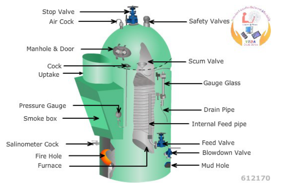
6.3 Feed, check, and blowdown valves
- Inspect seat and disc for erosion, wire drawing, and pitting.
- Renew packing and gaskets.
- Confirm smooth travel through the full range and correct position indication.
- Confirm the valve closes fully and does not pass when shut.
- On the feed check valve, confirm the non-return action and the freedom of the disc.
- On blowdown valves, confirm the correct opening sequence and the downstream line condition — a leaking blowdown valve is a continuous and easily-missed loss of water and heat.
6.4 Burner
- Clean the barrel, swirl plate, orifice plate, and tip, and inspect each for erosion, cracking, and carbon build-up.
- Check the orifice for diameter change from wear. A worn orifice changes the flow for a given pressure and changes the spray quality.
- Check the swirl plate holes for blockage and erosion.
- Check the cap and body seating for damage; renew the gaskets.
- Confirm the correct assembly order and seating in the carrier.
- Confirm the cooling or atomising passage is clear.
- Confirm the burner seats and clamps correctly, with no gas leakage past it.
- Confirm the safety shut-off arrangement operates with the burner: on many designs, removing the burner mechanically shuts off both fuel and atomising medium.
6.5 Flame scanner and igniter
- Clean the scanner lens and the sight tube. A dirty lens produces a false no-flame signal.
- Confirm the sight tube is unobstructed and correctly aligned.
- Prove the scanner detects a flame and produces the correct signal.
- Prove the scanner fails correctly — mask it, or use the approved test method, and confirm the burner trips.
- Check the igniter electrode gap, position, and insulation.
- Prove ignition with the full sequence, and confirm the igniter is proven before fuel is admitted.
6.6 Soot blowers
- Inspect the lance for straightness, erosion, and blockage.
- Inspect the nozzles for blockage, erosion, and correct orientation.
- Check the drive, gearing, and travel through the full blowing arc, and confirm the limit switches operate.
- Check the wall box, its seals, and the cooling air arrangement.
- Check the steam supply valve and drains, and confirm the drain arrangement operates as designed — open when the master valve is shut, closing once the line is warm and flowing.
- Confirm the orifice or restriction plates in the steam supply are fitted correctly and clear.
- Confirm the blower returns to its parked position clear of the gas path.

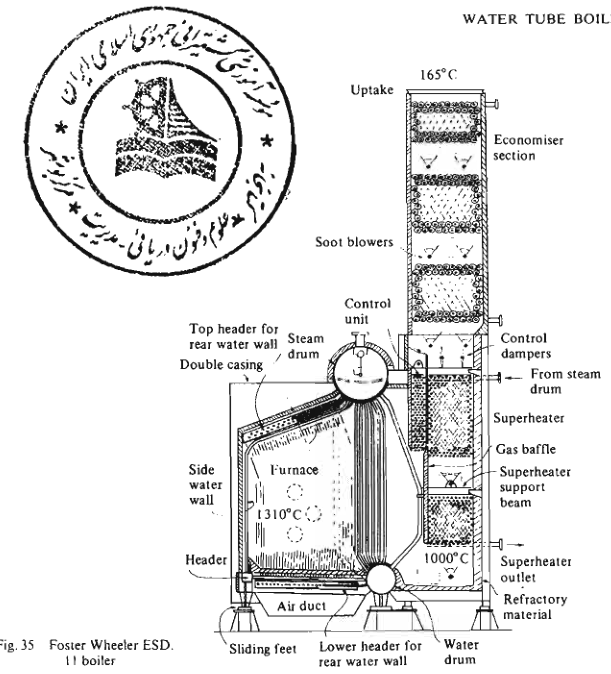
Prove each blower through its full travel and confirm the limit switches match the actual lance position; a blower that indicates parked while sitting in the gas path erodes within hours.
6.7 Fans, dampers, and actuators
- Inspect the impeller for erosion, cracking, corrosion, and imbalance.
- Check the bearings for wear, clearance, and lubrication condition.
- Check the coupling and confirm the alignment.
- Check the dampers, linkages, and actuators for free travel through the full range.
- Confirm position indication and limit switches correspond to the actual damper position. A damper whose indication disagrees with its position produces an air-fuel mismatch that the control system cannot detect.
- Confirm the fan casing and ducting are free of holes and blockages.
6.8 Refractory
- Inspect for cracking, spalling, and loose material.
- Inspect the burner quarl and the furnace floor, both of which take the highest thermal load and the most flame impingement.
- Confirm expansion gaps are clear and correctly sized. Refractory without expansion allowance cracks as the boiler heats.
- Check anchors and studs — the refractory has to be held in place, and a corroded or broken anchor lets it fall.
- Remove loose material completely before renewal.
- Renew with the correct material for the location, and follow the curing procedure. Refractory that is dried too quickly during its first firing cracks and loses its strength.
- Check the seal between the refractory and the casing where gas leakage could occur.
7. Pressure testing
7.1 Purpose
The hydraulic test proves the pressure boundary after repair or inspection. It is not a substitute for inspection — it proves tightness, not soundness.
7.2 Procedure
Confirm the boiler is clean, closed, and correctly filled with water. Air must be excluded — a hydraulic test on a boiler containing air is dangerous, because the air is compressible and stores energy.
Fit the correct test pressure gauges — calibrated, and with a range suitable for the test pressure.
Fill slowly and vent all air from the highest points.
Raise pressure gradually, in steps, watching the gauge and checking the accessible joints as the pressure rises.
Hold the test pressure for the required period, commonly at least 30 minutes.
Inspect all openings, manholes, handholes, tube ends, expanded joints, and welded joints. Look for weeping, dripping, and any sign of distortion.
Release pressure slowly. Rapid release produces its own thermal and pressure shock.
If a leak is found, drop the water level only far enough to repair it, then retest. Repeat until no leakage occurs.
Before draining, and after removing any gags, use the hydraulic pressure to reset the safety valves where the procedure allows. They then need only a final adjustment under steam.
If raw or untreated water was used for the test, drain and refill with treated water, or take the appropriate action for the water quality.
7.3 Distinction between test types
- Hydraulic test — proves tightness of the pressure boundary at the test pressure, with water.
- Steam test / operating test — proves the boiler under working conditions, including safety valve operation, control operation, and thermal behaviour.
Both have their place. A successful hydraulic test does not prove that the boiler will behave correctly under steam, and a boiler that ran correctly yesterday is not proven sound.
8. Returning to service
Confirm the boiler is clean and all tools, material, and scaffolding are removed. Count the tools.
Confirm all mountings are fitted and correct — gauge glasses, safety valves with their gags removed, pressure gauge, feed and blowdown valves, vents and drains.
Fill, vent, and check the gauge glasses.
Prove the alarms, trips, cut-outs, and flame failure protection before lighting.
Purge and light the burner using the full approved sequence, with no steps omitted.
Raise steam slowly, following the maker's warm-up requirements.
Test the low-water protection and the safety valves as required.
Check for leaks as pressure and temperature rise, particularly at joints that have been disturbed.
Do not tighten joints under pressure unless the specific procedure allows it for that joint.
Record everything — the repairs, the settings, the test results, and any outstanding defects.
9. The overhaul record
For each boiler, keep a record containing:
- Date and reason for the overhaul.
- Condition found, with location and extent — the more specific, the more useful next time.
- Repairs carried out, with materials and procedures.
- Pressure test results, including the test pressure, duration, and observations.
- Safety valve settings, with the test gauge reference and calibration date.
- Burner and control settings restored after overhaul.
- Tube map showing plugged and renewed tubes, and the date of each.
- Refractory and insulation work, with materials.
- Outstanding defects and the plan to address them.
- Names of the people who performed and supervised the work.
A boiler with a good record can be assessed in an hour. A boiler with no record has to be re-surveyed every time because nothing is known about its history.
10. Overhaul sequence
PREPARATION
1.  Authorise; prepare permits; brief the personnel
2.  Isolate fuel, steam, feedwater, blowdown, dosing, sampling, electrical
3.  Lock and tag; fit blanks where required
4.  Prove zero pressure independently
5.  Cool naturally; drain; vent
6.  Test atmosphere; ventilate; provide lighting, rescue, and an attendant
7.  Enter with confined-space discipline

INTERNAL
8.  Internal inspection: scale, sludge, pitting, cracking, bulging, erosion,
    overheating, leak paths, internal fittings, tube ends
9.  Note the location and character of every finding
10. Tube inspection: clear bores, bulges, welds, expansions
11. Find leaks: marks, hydraulic test, adjacent tubes, introscope
12. Repair: plug within limits, or replace; membrane wall repair where fitted
13. Prove tubes clear and plugs secure; pressure test
14. Update the tube map

EXTERNAL
15. Casing, insulation, supports, expansion arrangements, holding-down
16. Fuel system, burner, air register, fans, dampers, uptake, soot blowers
17. Check for corrosion under insulation and around mountings

MOUNTINGS
18. Overhaul safety valves: seat, disc, spindle, spring, floating ring
19. Overhaul gauge glasses, feed and check valves, blowdown valves
20. Overhaul burner, scanner, igniter, soot blowers, fans, dampers
21. Inspect and renew refractory; cure correctly

TESTING
22. Hydraulic test: fill, vent, raise in steps, hold, inspect, release
23. Reset safety valves using hydraulic pressure where permitted
24. Set and prove safety valves under steam
25. Prove alarms, trips, cut-outs, and flame failure protection

RETURN TO SERVICE
26. Confirm clean, closed, all tools removed
27. Fill, vent, check glasses
28. Purge, light, raise steam slowly
29. Check for leaks as temperature and pressure rise
30. Complete the record, including outstanding defects