

Marine Central Cooling Water System (HT / LT / SW)
Interactive marine central cooling water P&ID diagram: Sea Water, Low-Temperature (36 °C), and High-Temperature (85 °C) loops, plate coolers, thermostatic 3-way valves, and desalinator.
1. Interactive P&ID Line Diagram
The complete marine central cooling water system integrating Sea Water (SW), Low Temperature Fresh Water (LT FW, 36 °C), and High Temperature Fresh Water (HT FW, 85 °C) standardized into modern P&ID symbology. Hover over any symbol to inspect its specifications, and use mouse wheel or toolbar buttons to zoom and pan across the full vessel layout.
Reference: Ship's Piping Diagrams
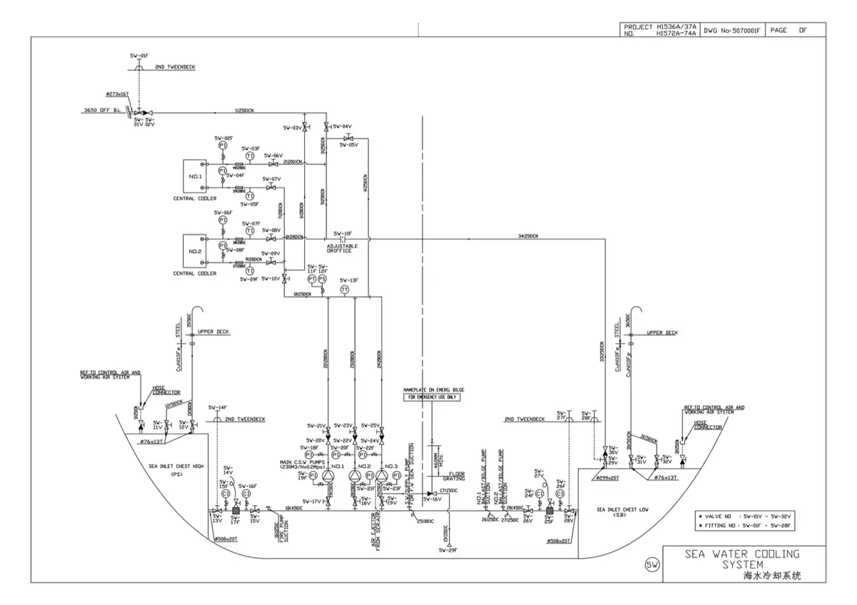
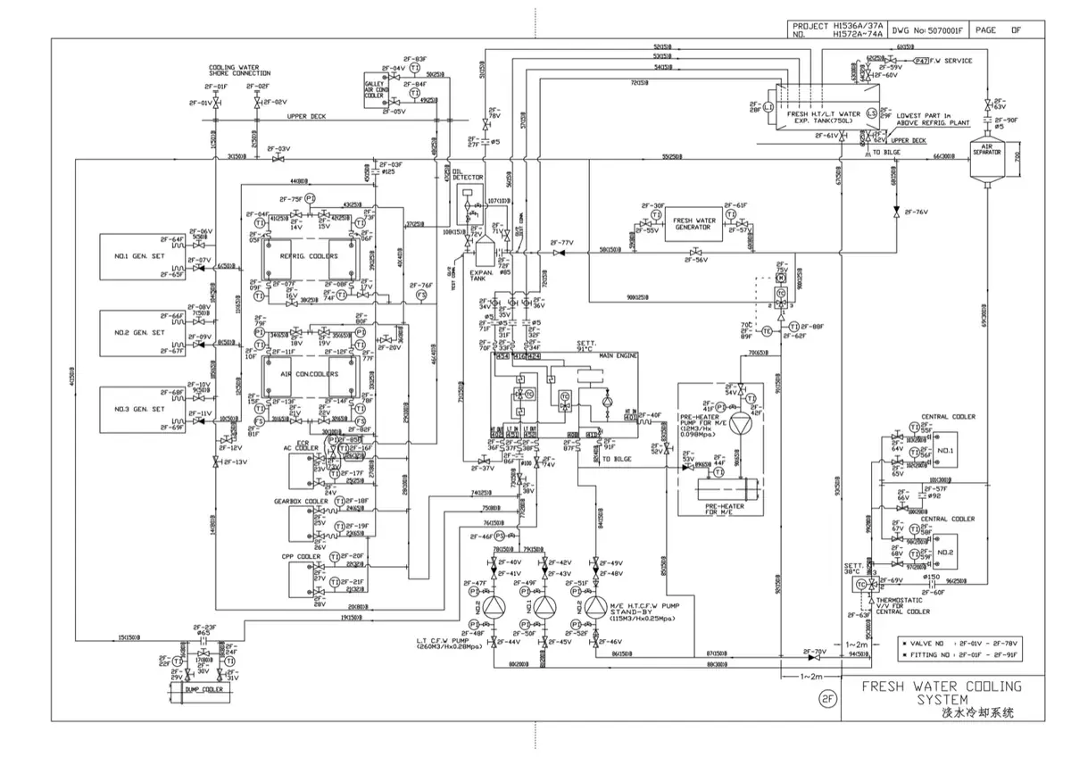
The two shipyard drawings below show the central cooling system split the way a yard draws it — the sea water side and the fresh water side as separate sheets. Read them together with the interactive diagram above: the sea water sheet carries the raw-water circuit, sea chests, strainers and the coolers that reject heat overboard, while the fresh water sheet carries the treated low-temperature and high-temperature circuits that cool the engine and its auxiliaries. Only the heat exchanger joins them, which is the whole point of a central cooling system.
2. System Flow: Three Coordinated Thermodynamic Circuits
Early motorships circulated raw seawater directly through engine cylinder heads and oil coolers. This caused catastrophic scaling, marine fouling, and severe galvanic pipe corrosion. The modern Central Cooling Water System solves this by confining raw seawater exclusively to two corrosion-resistant titanium central plate heat exchangers, while closed loops of clean, de-mineralized, chemically-treated fresh water circulate throughout the entire vessel.
The system operates via three distinct, interconnected circuits:
1. Sea Water (SW) Open Circuit
Raw seawater enters through either the High Sea Chest (used in shallow ports and muddy river estuaries to avoid dredging silt) or the Low Sea Chest (used in deep sea and heavy rolling to prevent air ingestion). It passes a duplex basket strainer and MGPS anti-fouling copper/aluminum anodes. Centrifugal SW pumps discharge the seawater through the two central titanium plate heat exchangers, where it absorbs shipboard heat and discharges overboard at ~32–38 °C.
2. Low Temperature Fresh Water (LT FW) Closed Circuit (36 °C)
Clean fresh water treated with sodium nitrite corrosion inhibitor circulates in a closed loop at ~3.5–4.0 bar. A 3-way thermostatic control valve modulates bypass flow around the central coolers to maintain a strictly uniform 36 °C supply header. The LT water branches in parallel to cool:
- Main Engine Lube Oil Cooler: Drops circulating system oil from ~55 °C to 45 °C at engine inlet.
- Scavenge Air Cooler (LT Stage): Cools turbocharger boost air to ~40–45 °C to boost combustion air density.
- Auxiliary Diesel Generators (A/Es): Cools lube oil and jacket water for ship electrical generators.
- Refrigeration & Air Conditioning Condensers: Freon condensers cooled without marine bio-fouling.
3. High Temperature Fresh Water (HT FW) Closed Circuit (85 °C)
Dedicated high-temperature circuit for cooling the main engine combustion zone. Circulating pumps deliver water at ~80 °C into the lower cylinder jacket inlet manifold. The water spirals upward around each cylinder liner, cooling the combustion chamber collar and cylinder covers before discharging at ~88 °C (temperature rise strictly ≤ 10 °C).
The hot discharge divides between:
- Fresh Water Generator (Vacuum Evaporator): Uses 85 °C waste heat to evaporate seawater under vacuum, producing distilled drinking water without consuming fuel.
- HT 3-Way Thermostatic Control Valve: In normal sea-going operation, it acts 2-way, diverting excess heat to the LT return line to be cooled by the Central Coolers. The direct recirculation port back to pump suction is only used during initial engine warmup.
- Jacket Pre-Heater: Steam heat exchanger used in port to keep cylinder blocks at ≥ 60 °C before starting. Isolated during sea passage.
3. Sea Chest Operation & Marine Growth Prevention
Vessels feature at least two sea chests on opposite sides and levels of the hull:
| Feature | High Sea Chest (Side Shell) | Low Sea Chest (Bottom / Keel) |
|---|---|---|
| Location | Side shell plating above the bilge turn | Bottom plating near the center keel |
| Operating Mode | Ports, rivers, shallow anchorages, canals | Deep sea oceanic passage, heavy rolling |
| Primary Purpose | Prevents dredging mud, sand, and silt into coolers | Guarantees continuous flooded suction in heavy seas |
| Anti-Fouling | Steam blow-down & de-icing connections | MGPS copper and aluminum sacrificial anodes |
4. Expansion & De-Aerating Tank Functions
The common expansion and de-aerating tank sits at the highest point of the vessel (boat deck level) and performs four indispensable safety roles:
- Thermal Expansion: Fresh water expands by ~3–4% as it heats from ambient to 88 °C. The expansion tank accommodates this volume surge without pressure spiking.
- Static Positive Head: Provides 1.5–2.0 bar of static gravity pressure at pump suctions, raising Net Positive Suction Head Available (NPSHA) and preventing impeller cavitation.
- Continuous De-Aeration: High-point vent lines from cylinder heads bleed out entrained air bubbles and early combustion gas leaks (such as blown cylinder head gaskets or cracked cylinder covers) before air locks can starve the jackets of cooling water.
- Chemical Dosing: Serves as the introduction vessel for corrosion inhibitors (sodium nitrite / borate), maintaining a protective passivating gamma-iron oxide film on internal cast-iron surfaces.
Practise this in the question bank
- Cooling Water System — 15 questions
Found a mistake, or something unclear?
Report it in a few seconds — it goes straight to the editors.
- Fuel Oil System — Interactive One-Line Diagram
- Marine Compressed Air & Main Engine Starting Air System
- Marine Central Cooling Water System (HT / LT / SW)
- Lubricating Oil System — Interactive One-Line Diagram
- Bilge, Ballast & Fire Main System — Interactive One-Line Diagram
- Steering Gear — Interactive One-Line Diagram
- Steam and Condensate System — Interactive One-Line Diagram