

Lubricating Oil System — Interactive One-Line Diagram
Interactive main engine lubricating oil P&ID: drain tank, main and pre-lube pumps, LO cooler, 3-way thermostatic valve, full-flow duplex filter, flanges R, U and Y, purifier loop and the alarm, slow-down and shut-down limits.
1. Interactive P&ID Line Diagram
The complete main-engine lubricating oil system, from the drain tank through the pumps, cooler, thermostatic valve and full-flow filter to the three engine flanges, with the purifier loop, storage and filling arrangements and the full safety instrument set. Hover over any symbol to inspect its specifications, and use the mouse wheel or the toolbar buttons to zoom and pan across the layout.
Reference: Ship's Piping Diagram
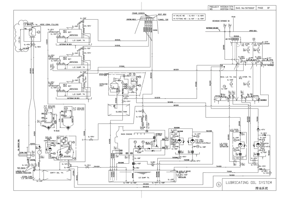
Alongside the interactive diagram above, here is the same circuit as drawn by a shipyard in an engine-room piping diagram booklet. Comparing the two is genuinely useful practice: the symbol conventions and the layout differ from the teaching diagram, but the circuit is recognisably identical — drain tank, suction strainer, main pumps, cooler, thermostatic valve, full-flow filter, then the three engine flanges, with gravity return and the purifier side loop.
2. System Flow: From the Drain Tank Back to the Bearings
MAN B&W describe the circuit in a single sentence, and it is worth memorising in exactly that order: "The lubricating oil is pumped from a bottom tank by means of the main lubricating oil pump to the lubricating oil cooler, a thermostatic valve and, through a full-flow filter, to the engine inlet RU."
Stage 1: Drain Tank and Suction
The drain tank sits directly beneath the engine so that every bearing, piston and camshaft drains back into it by gravity alone — there is no return pump to fail. Oil leaves through a coarse duplex suction strainer, and the tank's suction box is arranged so the pumps remain flooded at up to 15 degrees of list and trim. A cofferdam surrounds the tank so that a leak shows up as a controlled alarm rather than as oil in the bilge.
Stage 2: Pumping
Two main pumps of 100 percent capacity each are fitted, one running and one on automatic standby. They are positive-displacement screw pumps, chosen because they deliver a steady volume regardless of pressure and are gentle on the oil. A third, much smaller pre-lubrication pump runs before starting and after stopping the engine. Because a positive-displacement pump will destroy itself or its pipework if the discharge is blocked, a pressure control valve spills oil back to suction and holds the working pressure steady.
Stage 3: Cooling and Temperature Control
The oil leaves the engine at roughly 55–60 °C and must be delivered at about 45 °C. A plate cooler transfers that heat into the low-temperature fresh water circuit. The control element is the 3-way thermostatic valve: its feeler bulb senses the oil temperature at the engine inlet and proportions flow between the cooler and a bypass. When the engine is cold the valve sends most of the oil round the bypass, which is why the engine warms up quickly instead of being over-cooled.
Stage 4: Full-Flow Filtration
Every drop of oil going to the engine passes through the full-flow filter — it is a full-flow, not a bypass, filter, because unfiltered oil reaching a bearing is a wiped bearing. Absolute fineness is about 40 micrometres, and 85 to 90 percent of particles larger than 25 micrometres are retained. Maximum pressure drop is 0.2 bar clean and the element is changed at 0.5 bar. It is mounted as close to the engine as possible, and the duplex arrangement lets one side be cleaned with the engine running.
Stage 5: Distribution Through Three Flanges
Oil enters the engine at flange RU and divides internally into three distinct service streams:
- Flange U — the largest share rises through the telescopic pipe to each crosshead and then branches three ways: down a central pipe inside the piston rod for piston cooling (returning through the annular space), to the crosshead bearing upper half and guide shoe sliding surfaces, and through a bore in the connecting rod to the bottom end bearing.
- Flange R — a second portion lubricates the main bearings, the chain drive and the thrust bearing.
- Flange Y — the camshaft booster pumps lift the oil to a higher pressure for the camshaft bearings, roller guides and exhaust valve actuators.
The split between piston cooling and the main bearings is set by a single butterfly valve or orifice plate, adjusted once at commissioning and then locked.
Stage 6: Return and Continuous Purification
All oil drains back to the tank by gravity and starts the circuit again. In parallel, a purifier continuously draws a side stream from the drain tank and centrifuges out water, sludge, carbon and wear metal that the filter cannot hold, discharging clean oil to the storage tank. This side loop is what allows the same oil to serve for years of running.
3. Critical Components: Working Principles & Design Specs
| Component | Type / Standard | Working Principle & Internal Operation | Why It Matters |
|---|---|---|---|
| Main LO pumps | Positive-displacement screw pump, 2 × 100% | Intermeshing helical screws trap pockets of oil and advance them axially at constant volumetric displacement, independent of back-pressure. Gentle, pulsation-free and self-priming. | Delivers a steady flow whatever the system resistance. The duplicate arrangement means a pump failure never costs the engine its bearings. |
| Pressure control valve | Spring-loaded relief, bypass to suction | Rises off its seat once discharge pressure exceeds the spring setting and spills oil straight back to the pump suction. | Non-negotiable on a positive-displacement pump: with the discharge shut, pressure would otherwise rise until a pipe or casing burst. |
| 3-way thermostatic valve | Self-actuated blending valve with feeler bulb | The bulb senses engine inlet oil temperature and moves a single piston that proportions flow between the cooler and the bypass. Hot oil gets diverted through the cooler; cold oil recirculates. | Holds the engine inlet at about 45 °C at every load, and gives fast warm-up from cold. Oil that is too cold is too viscous to reach the far ends of the system. |
| LO cooler | Plate heat exchanger, LT fresh water cooled | Corrugated plates give a large surface area in a small volume with high turbulence. Oil enters at about 55–60 °C and leaves at about 45 °C. | Cooling with treated fresh water rather than raw sea water keeps the oil side free of scale, corrosion and marine growth. |
| Full-flow filter | Duplex, 40 µm absolute | Every drop passes through the element. 85–90% of particles above 25 µm are retained. ΔP 0.2 bar clean, element changed at 0.5 bar. Mounted as close to the engine as practicable. | A full-flow filter is a safety device, not a convenience: unfiltered oil reaching a bearing destroys it. Duplex design allows cleaning without stopping the engine. |
| Camshaft booster pumps | Small dedicated pumps, 2 × 100% | Take oil from the main supply and raise it to a considerably higher pressure for the camshaft circuit. | Camshaft, roller guides and exhaust valve actuators need far more pressure than the main bearings, so a separate boosted circuit is used. |
| Pre-lubrication pump | Small independently driven pump | Run before starting to flood every bearing and piston with oil, and after stopping to carry heat away from hot bearings and turbocharger parts. | Prevents the dry start that scuffs bearings and cylinder liners, and prevents oil cooking onto hot surfaces after shutdown. |
| LO purifier | High-speed disc-stack centrifuge | Bowl spins at thousands of rpm generating thousands of g. Water and dense particles are thrown to the outer wall and discharged as sludge while clean oil leaves from the centre. | Removes water, sludge and wear metal that a filter cannot hold. This side loop is what keeps the oil serviceable for years. |
4. LO Safety Devices: Alarm, Slow-Down and Shut-Down Limits
The lubricating oil system carries more protective devices than any other system on the engine, because a loss of oil pressure destroys bearings in seconds. MAN B&W specify the following alarm, slow-down and shut-down arrangements for the engine lubricating oil system:
| Monitoring Point | Condition | Type of Safety Action | Operating Value |
|---|---|---|---|
| Inlet to engine | Low temperature | Alarm | 35 °C |
| Outlet from engine (inlet to cooler) | High temperature | Alarm | 60 °C |
| Inlet to main and thrust bearings | Low pressure | Alarm → slow down → shut down | Staged, in that order |
| Crankpin bearing outlet | Deviation from average | Alarm | ± 5 °C |
| Crankpin bearing outlet | Deviation from average | Slow down | ± 7 °C |
| Crosshead bearing outlet | Deviation from average | Alarm | ± 5 °C |
| Crosshead bearing outlet | Deviation from average | Slow down | ± 7 °C |
| Thrust bearing segment | High temperature | Alarm | 70 °C |
| Thrust bearing segment | High temperature | Slow down | 75 °C |
| Drain tank | Low level | Alarm (and often start inhibit) | Per maker's scheme |
Why Bearing Temperatures Are Watched as a Deviation
An absolute temperature limit would be almost useless for a crankpin or crosshead bearing, because the normal reading depends on ambient conditions, engine load and oil temperature. What actually signals a fault is one unit running hotter than its neighbours. The alarm is therefore set at ± 5 °C and the slow down at ± 7 °C from the average of all units, which detects a single wiped or wrongly fitted shell long before any absolute limit would be reached.
Why Pressure Protection Is Staged
Lubricating oil pressure protection acts in three stages rather than one. A momentary dip triggers the standby pump to auto-start and raises an alarm; a sustained fall slows the engine down, which reduces the heat being generated and gives the operator time to react; only a continued fall shuts the engine down. Slowing down before stopping matters because an immediate stop under full load can itself damage a hot, still-turning engine.
Working Parameters
Engine inlet temperature approximately 45 °C · working viscosity at that temperature 90–100 cSt · supply pressure roughly 2–4 bar · filter ΔP 0.2 bar clean / 0.5 bar dirty at 40 µm absolute · drain tank suction arranged for up to 15° of list and trim.
5. High-Frequency Oral Exam Questions
-
Sketch and describe the main engine lubricating oil system of a large two-stroke engine, and state the LO safety devices.
Oil drains by gravity from every bearing, piston and camshaft into the drain tank beneath the engine. Two main screw pumps of 100 percent capacity each draw through a coarse duplex suction strainer and discharge through a pressure control valve that spills excess oil back to suction. The oil passes the LO cooler, where a 3-way thermostatic valve proportions flow between the cooler and a bypass to hold about 45 °C at the engine inlet, then through a full-flow duplex filter of about 40 µm absolute. It enters the engine at flange RU and divides three ways: flange U to the telescopic pipe for piston cooling, crosshead bearing, guide shoe and bottom end bearing; flange R to the main bearings, chain drive and thrust bearing; and flange Y, via the camshaft booster pumps, to the camshaft bearings, roller guides and exhaust valve actuators. A small pre-lubrication pump runs before starting and after stopping. A purifier side loop continuously removes water, sludge and wear metal. Safety devices are: low temperature alarm at 35 °C at the engine inlet; high temperature alarm at 60 °C at the engine outlet; staged low-pressure alarm, slow down and shut down at the main and thrust bearings; crankpin and crosshead outlet temperature deviation alarms at ± 5 °C and slow down at ± 7 °C; thrust bearing segment alarm at 70 °C and slow down at 75 °C; and drain tank low level alarm.
-
Why is the 3-way thermostatic valve fitted, and what would happen without it?
It holds the oil temperature at the engine inlet at about 45 °C regardless of engine load or ambient temperature, by proportioning flow between the LO cooler and a bypass. Without it the oil would be over-cooled at low load and under-cooled at full load. Oil that is too cold is too viscous to flow properly to the ends of the system, so bearings and piston cooling passages would be starved while the pump pressure still looked normal; oil that is too hot loses its load-carrying film and oxidises rapidly. The valve also gives fast warm-up from cold, because it recirculates hot oil instead of sending everything through the cooler.
-
Why are two main LO pumps fitted, and why is a pressure control valve essential?
Two pumps of 100 percent capacity each, one duty and one standby on automatic start, mean that a pump failure cannot cost the engine its bearings — the standby cuts in on low pressure almost instantly. The pressure control valve is essential because the pumps are positive-displacement screw pumps: they move a fixed volume of oil per revolution regardless of resistance. If the discharge were restricted, pressure would rise until a pipe, gasket or pump casing failed. The valve spills oil back to suction and holds a steady working pressure, and the same principle is why a screw pump must never be started against a closed discharge valve.
-
Why are bearing temperatures monitored as a deviation from the average rather than against a fixed limit?
Because the normal bearing outlet temperature depends on engine load, ambient conditions and the oil inlet temperature, a single absolute limit would either alarm constantly or never alarm at all. The meaningful signal is one unit running hotter than the others, which indicates a local fault such as a wiped bearing shell, a blocked oil passage or a wrongly fitted bearing. Setting the alarm at ± 5 °C and the slow down at ± 7 °C from the average of all units detects that local fault long before any absolute temperature limit would be reached.
-
Why does a full-flow filter need to be duplex, and what is the purpose of the purifier if the oil is already filtered?
The filter is full-flow, so every drop of oil going to the engine passes through it — stopping the engine to change an element is not an option, so a duplex body with a changeover valve lets one side be cleaned while the other carries the full flow. The purifier does a completely different job from the filter: a filter holds solid particles down to a few micrometres but cannot remove water or dissolved contaminants, whereas the centrifuge separates water and dense sludge by density. The two are complementary — the filter protects the bearings in the short term, and the purifier keeps the oil chemically serviceable over years of running.
Practise this in the question bank
- Lubrication System — 31 questions
Found a mistake, or something unclear?
Report it in a few seconds — it goes straight to the editors.
- Fuel Oil System — Interactive One-Line Diagram
- Marine Compressed Air & Main Engine Starting Air System
- Marine Central Cooling Water System (HT / LT / SW)
- Lubricating Oil System — Interactive One-Line Diagram
- Bilge, Ballast & Fire Main System — Interactive One-Line Diagram
- Steering Gear — Interactive One-Line Diagram
- Steam and Condensate System — Interactive One-Line Diagram