

Marine Compressed Air & Main Engine Starting Air System
Interactive marine starting air P&ID diagram: 30-bar compressors, receivers, fusible plugs, turning gear interlock, master starting valve, distributor, and cylinder starting valves.
1. Interactive P&ID Line Diagram
The complete marine main engine compressed air and starting air system standardized into modern P&ID symbology. Hover over any symbol to inspect its specifications, and use mouse wheel or toolbar buttons to zoom and pan across the full vessel layout.
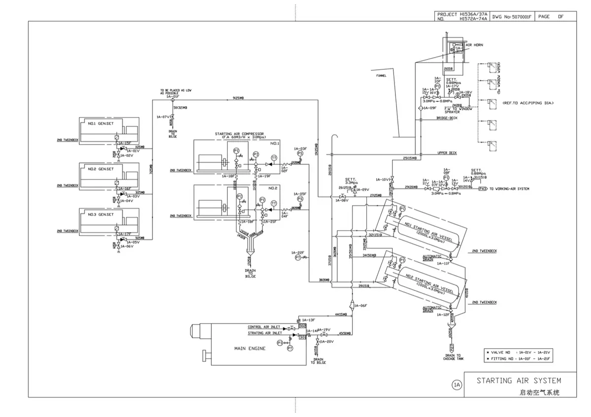
Reference: Ship's Piping Diagram
The shipyard drawing of the same system is below. Where the interactive diagram standardises symbols for teaching, the ship's drawing uses the yard's own conventions and adds the practical detail a builder needs — bottle drains, relief devices, isolation and interlocking of the starting air to the turning gear and the main starting valve. Trace the same path through both: compressors, air bottles, the main starting valve, the distributor and the cylinder starting valves.
2. System Flow: From Ambient Suction to Cylinder Starting
Large marine two-stroke diesel engines cannot be cranked by electric starter motors due to their immense reciprocating mass and compression pressures. Instead, high-pressure compressed air at 30 bar is injected directly onto the piston crowns in firing sequence to spin the engine up to firing speed (~15–20 rpm), at which point heavy fuel oil injection commences.
The system operates across six coordinated thermodynamic and pneumatic stages:
Stage 1: Two-Stage Compression & Moisture Separation (30 Bar)
Dual motor-driven reciprocating compressors draw atmospheric air through dry felt suction filters. The Low-Pressure (LP) piston compresses air to ~4.5 bar (reaching ~140–160 °C). Air passes through a tubular seawater intercooler where temperature drops to ~35 °C, causing large quantities of water vapor to condense. The condensate is separated by centrifugal baffles and dumped by auto-drain traps. The High-Pressure (HP) piston compresses the dry air to 30 bar (~150 °C), followed by an aftercooler and non-return discharge valve.
Stage 2: High-Pressure Storage in Dual Receivers (SOLAS II-1/31)
Air enters two independent welded-steel receivers (No. 1 & No. 2), each sized to provide at least 12 consecutive starts for a reversible propulsion engine (or 6 starts for non-reversible) without replenishment. Each vessel features a spring relief valve set at 1.1 × working pressure (33 bar), a eutectic fusible safety plug (121 °C), remote quick-acting isolation stop valves, and automatic/manual bottom drain traps.
Stage 3: Pressure Reduction to Control & Instrument Air (7 Bar)
A branch line drops from the 30-bar header into a duplex pressure-reducing station. Self-acting diaphragm regulators step the pressure down to 7.0–8.0 bar. The air passes through a refrigerated air dryer (lowering pressure dew point to +3 °C) and a 0.01 µm micro-coalescer oil filter into the 7-bar Control Air Receiver, supplying exhaust valve air springs, engine governors, maneuvering telegraphs, and ship's whistle.
Stage 4: Turning Gear Mechanical Safety Interlock
Starting air from the receivers routes through the Turning Gear Interlock Valve. This mechanical valve is physically coupled to the engine turning gear engagement lever. Whenever the turning gear pinion is meshed with the flywheel ring gear, starting air is blocked and the downstream pipe is vented to atmosphere. This physically guarantees that starting air cannot enter the engine while the turning gear is engaged, preventing gear tooth stripping or motor destruction.
Stage 5: Master Starting Air Valve & Slow-Turning Sequence
Air reaches the Automatic Master Starting Air Valve. When an engine start command is given from the bridge or ECR, the system first executes an automated Slow-Turning Sequence: a small solenoid bypass admits a throttled trickle of air that gently rotates the crankshaft at 2–3 rpm for one revolution. If an indicator cock spurts water or fuel (indicating a leaking cylinder head or injector hydrostatic lock), starting aborts immediately, saving connecting rods from bending. If clear, the master valve's operating piston receives full pilot air and slams the main valve disc open, charging the 30-bar manifold.
Stage 6: Distributor Timing & Cylinder Starting Valve Injection
Simultaneously, 30-bar pilot air feeds the Starting Air Distributor driven by the camshaft. The distributor's internal timing disc directs pilot air pulses to the active cylinder whose piston is between 0° (TDC) and 110° ATDC on its power stroke. The pilot air forces down the operating piston of that Cylinder Starting Air Valve, opening the main poppet disc against its return spring. High-pressure 30-bar air rushes onto the piston crown, driving it downward. As the crank reaches ~110°, the distributor vents that cylinder's pilot line, allowing the spring to snap the valve shut before exhaust port opening.
3. Critical Components: Working Principles & Design Specs
| Component | Design Standard | Working Principle & Internal Operation | Safety & Regulatory Function |
|---|---|---|---|
| Fusible Safety Plug | SOLAS II-1/31 Eutectic alloy (121 °C) |
A threaded bronze plug containing a central core of low-melting eutectic bismuth/cadmium/lead alloy. Normally withstands 30 bar hydrostatic pressure. | In an engine room fire, ambient heat melts the alloy core at 121 °C (250 °F), safely venting all 30-bar air into the machinery space and preventing explosive receiver rupture (BLEVE). |
| Turning Gear Interlock | Class & SOLAS mandatory | Spool valve physically coupled to turning gear engagement lever. In engaged position, spring pushes spool to isolate supply and vent downstream line. | Prevents high starting air torque from rotating the flywheel while the high-ratio electric turning gear worm is meshed, avoiding catastrophic gear teeth shearing. |
| Automatic Master Air Valve | Piston-balanced non-return valve | Internal valve disc has a balance piston on the spindle. Spring keeps it closed against 30 bar. Start signal admits pilot air above piston to snap it open. | Isolates the engine starting manifold during normal running. Automatically vents the manifold to atmosphere via a vent hole when closed, ensuring no lingering pressure. |
| Flame Arrestor | Stainless steel / brass wire gauze pack | Stack of corrugated fine wire mesh discs positioned immediately upstream of the manifold. Quenches flame fronts below ignition temperature. | Prevents burning combustion gases from a leaking cylinder starting valve from traveling backward into the starting air manifold and igniting lubricating oil vapor mist. |
| Bursting Cap / Disc | Tear-type relief diaphragm (35–40 bar) | Thin brass or stainless steel sheet clamped in a vented flange casing with a protective cowl. | Relieves explosive pressure spikes instantaneously during an air line explosion, venting shock waves safely before the heavy steel manifold ruptures. |
| Cylinder Starting Valve | Differential piston poppet valve | Held closed by gas pressure and heavy coil spring. Timed 30-bar pilot air enters top chamber above a larger diameter piston, overcoming spring and opening valve. | Delivers 30-bar starting air onto piston crown between 0° and 110° ATDC. Closes immediately when distributor vents pilot air, sealing combustion chamber. |
4. Thermodynamics of Staged Air Compression
Compressing air from atmospheric pressure (1.0 bar) to 30 bar in a single stage is physically impractical on ships because the discharge temperature would exceed 450 °C, causing immediate auto-ignition of cylinder lubricating oil and severe thermal expansion seizures. Therefore, multi-stage compression with intercooling is universal.
Under optimal multi-stage compression theory, the total compression work is minimized when each stage shares an identical pressure ratio rp:
The intercooler extracts heat at constant pressure between stages. Because the volume of air decreases proportionally with absolute temperature (V ∝ T), cooling the air from ~150 °C down to ~35 °C before it enters the HP cylinder significantly reduces the volume to be compressed, saving up to 15–20% in compressor shaft power while condensing over 80% of ambient moisture.
5. Regulatory Requirements (SOLAS & Class)
SOLAS Chapter II-1, Regulation 31: Starting Air Capacity
- Twin Compressors: At least two independent air compressors must be provided, powered by separate electrical circuits or prime movers. Their combined capacity must charge the receivers from atmospheric pressure to full working pressure (30 bar) within 1 hour.
- Receiver Redundancy: At least two independent starting air receivers must be installed. For reversible main propulsion engines, the stored air must provide at least 12 consecutive starts (alternating ahead and astern) without replenishing the receivers. For non-reversible engines, at least 6 starts are required.
- Cold Ship Start: Ships must have an independent Emergency Air Compressor (hand-cranked or started by dedicated battery/small diesel engine) capable of starting auxiliary diesel generators from total blackout (dead-ship condition).
Starting Air Line Explosion Prevention
The most hazardous failure in compressed air systems is a Starting Air Manifold Explosion. If compressor piston rings wear, lubricating oil carries over into the receivers and manifold. If a cylinder starting valve leaks hot combustion gas back into the manifold, the oil vapor-air mixture detonates, creating shock waves exceeding 100 bar that can shatter the cast-iron manifold. SOLAS mandates: (1) Automatic or manual receiver drains blown down daily; (2) Flame arrestors and bursting discs at manifold inlets; (3) Non-return valves on compressor discharges; and (4) Relief valves on cylinder starting branches.
6. High-Frequency Oral Exam Questions
-
What causes a starting air line explosion onboard ship, and what safety devices prevent catastrophic manifold rupture?
Answer: A starting air line explosion requires three elements: fuel (lubricating oil carried over from air compressors and vaporized into aerosol droplets), oxygen (high-pressure 30-bar compressed air), and an ignition source (hot combustion gas blowing past a leaking or stuck-open cylinder starting air valve during the engine's power stroke). When flame enters the manifold, the oil mist detonates with supersonic flame speeds. Protection is provided by: (1) Flame arrestor packs at the manifold inlet to quench flames below the auto-ignition point; (2) Bursting caps / discs designed to rupture at ~35–40 bar and safely vent shock waves to atmosphere; (3) Safety relief valves; and (4) Daily drainage of air receiver bottom drains and compressor inter/aftercooler water separators.
-
Why is the Slow-Turning routine mandatory before starting a marine two-stroke diesel engine that has been stopped for more than 30 minutes?
Answer: While stopped, water can leak into a cylinder from cracked cylinder liners, cylinder head water jackets, or exhaust valve cages, or fuel can drip from a leaking injector nozzle. Because liquids are virtually incompressible, admitting full starting air or fuel into a cylinder containing trapped liquid would create astronomical hydrostatic pressures when the piston approaches Top Dead Center (TDC). This will bend the connecting rod, crack the cylinder head, or shear bearing studs. Slow turning rotates the crankshaft at ~2–3 rpm with indicator cocks cracked open, allowing engineers to verify clear cocks and safely abort before full torque is applied.
-
How does the Turning Gear Interlock Valve work, and what would happen if it failed to operate?
Answer: The turning gear interlock is a mechanically actuated valve linked to the lever that meshes the turning gear pinion with the flywheel ring gear. In the engaged position, the valve spool is pushed closed, cutting off pilot air to the master starting valve and venting the downstream circuit to atmosphere. If this valve failed to operate and starting air was admitted while the turning gear was engaged, the 30-bar starting air would rotate the engine with immense torque, instantly stripping all gear teeth off the turning gear pinion and flywheel, and violently destroying the high-speed electric turning motor.
-
What is the purpose of the Fusible Plug on an air receiver, and what is its melting point?
Answer: An air receiver contains a massive quantity of potential pneumatic energy (5.0 m³ at 30 bar). In the event of an engine room fire, radiant heat weakens the steel receiver shell while simultaneously heating the compressed air and raising internal pressure. If the shell yields under pressure, a devastating Boiling Liquid Expanding Vapor Explosion (BLEVE) or shrapnel explosion would occur. The fusible plug contains a bismuth alloy core that melts at exactly 121 °C (250 °F), completely discharging the 30-bar air safely into the atmosphere before the receiver steel reaches its tensile failure point.
Standards & sources referenced
- SOLAS: International standards for the safety of life at sea.
- Conventions index
Found a mistake, or something unclear?
Report it in a few seconds — it goes straight to the editors.
- Fuel Oil System — Interactive One-Line Diagram
- Marine Compressed Air & Main Engine Starting Air System
- Marine Central Cooling Water System (HT / LT / SW)
- Lubricating Oil System — Interactive One-Line Diagram
- Bilge, Ballast & Fire Main System — Interactive One-Line Diagram
- Steering Gear — Interactive One-Line Diagram
- Steam and Condensate System — Interactive One-Line Diagram