

Bilge, Ballast & Fire Main System — Interactive One-Line Diagram
Interactive bilge, ballast and fire main P&ID: bilge wells, mud boxes, screw-down non-return valves, the three bilge pumps, oily water separator and 15 ppm monitor, bilge injection valve, fire main with emergency fire pump, and the ballast main with change valve chest.
1. Interactive P&ID Line Diagram
The complete ship service system, showing how the bilge, fire and ballast circuits share the same three pumps. Bilge water is drawn from the port, starboard and aft wells through mud boxes and screw-down non-return valves into the bilge main, then pumped either through the oily water separator to overboard or straight overboard in an emergency. The fire main is fed by the fire and bilge pump and the general service pump, with the emergency fire pump and its isolating valve outside the machinery space. The ballast system fills and empties the tanks through the change valve chest. Hover over any symbol to inspect its operation and the regulation that governs it, and use the mouse wheel or the toolbar buttons to zoom and pan.
Reference: Ship's Piping Diagram
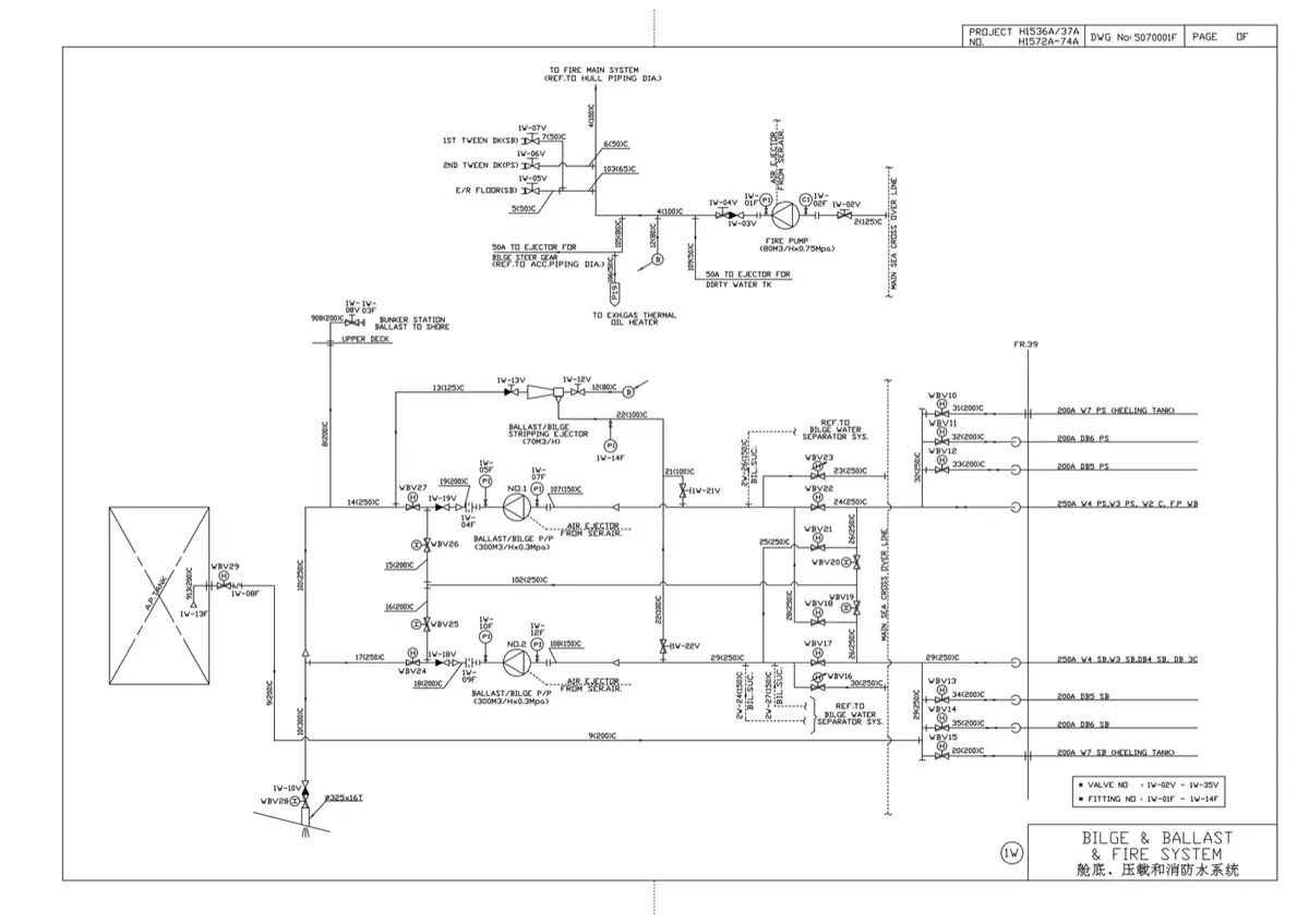
The shipyard drawing below covers the bilge, ballast and fire main as one combined sheet, which is how it is normally presented — the three services share pumps, piping runs and the sea suction, and the drawing makes those shared connections explicit. Compare it with the interactive diagram above and note the changeover arrangements: the same pump is arranged to serve bilge duty or ballast duty, but never both at once, and the fire main is kept independent so that a flooding casualty does not cost you fire-fighting capacity.
2. System Flow: Three Systems, One Set of Pumps
The essential purpose of a bilge system is to clear water from the ship dry compartments in an emergency. In practice its main work is much more mundane: clearing the water and oil that accumulate in the machinery space bilges through leakage and draining, and pumping out dry cargo holds after washing down.
Stage 1: Collection in the Bilge Wells
Bilge water collects in wells at the lowest points of the space — port and starboard in the machinery space, and one aft under the tunnel and stern gland. Each well has a mud box, a strainer box that traps sludge, rags and scale before it can reach a pump, and each branch ends in a screw-down non-return valve. The non-return disc matters more than it looks: without it, water from the sea, from the ballast line or from a flooded neighbouring compartment could travel back up a bilge branch and flood a compartment that was previously dry.
Stage 2: The Bilge Main
All the branches lead to the bilge main. On the diagram the main is the vertical trunk that the wells feed from the left and the pumps draw from on the right. A real bilge main in the engine room has connections from the dry cargo holds, the tunnel and the machinery spaces. Tanks for liquid cargo and ballast are not connected to it, because the two systems are incompatible; where a deep tank does double duty as a dry cargo space and a ballast tank, it is connected through a spectacle blank or a change-over chest so the two systems can never be joined by accident. Accommodation spaces are served separately by scuppers with non-return valves at the ship side.
Stage 3: The Pumps
Regulations require three or four power operated bilge pumps in the machinery space, depending on the size and type of ship. On the arrangement shown there are three: the fire and bilge pump, the general service pump and the auxiliary bilge pump. For smaller vessels one of the pumps may be main engine driven, but the other must be independently driven. A bilge ejector is acceptable as a substitute for a pump provided it can give an adequate flow rate; the figure usually quoted is at least 120 metres per minute through the pipe.
All statutory bilge pumps must be self-priming or able to be primed. The pumps may be used for other intermittent duties — general service, ballast and fire fighting — but a statutory bilge pump may not be used for a continuous duty such as cooling, because it must be available for its proper job.
Stage 4: The Auxiliary Bilge Pump and the Separator
The auxiliary bilge pump is the workhorse of the system and is normally not one of the statutorily required bilge pumps. It is a low capacity, smooth flow pump, chosen deliberately because it feeds the oily water separator: a pump that broke the oil into fine droplets would make separation far harder, and the whole design of the separator depends on oil arriving as large globules that can rise quickly. It also has a direct bilge suction to the aft well, independent of the main.
Stage 5: Separation and Discharge
Bilge water enters the separator at a large, slow-flowing inlet so that big oil slugs can surface at once. The flow is then turned vertically, passed over angled coalescing surfaces and finally through a fine gauze coalescer that joins small globules into large ones, while weirs reduce the depth of liquid at the surface so the oil layer can be skimmed. A 15 ppm bilge alarm and oil content monitor watches the outlet continuously; if the oil content rises above 15 ppm the alarm sounds and the discharge is stopped.
Oil skimmed off goes to the sludge or oil residue tank, from where it is landed ashore, burned in the incinerator, or burned as fuel in an approved sludge burner — never pumped overboard. Treated water below 15 ppm may go overboard, but only outside a special area, more than 12 nautical miles from the nearest land, while the ship is proceeding en route.
Stage 6: The Fire Main
The fire and bilge pump and the general service pump also discharge into the fire main, and regulations require the fire pumps — excluding the emergency fire pump — to be capable of delivering a total quantity of water at a defined head of not less than two thirds of the total bilge pumping capacity. The defined head ranges from 3.2 bar for a passenger ship of 4000 gross tons or more down to 2.4 bar for a cargo ship of less than 1000 gross tons.
An isolating valve is fitted outside the machinery space. When it is shut, the machinery space section of the main is separated from the rest of the ship, and every hydrant outside the machinery space can still be supplied by the emergency fire pump. That is the whole logic of the arrangement: a fire in the engine room must not be able to take the fire main out of service for the rest of the ship.
Stage 7: Ballast
The ballast pump takes suction from its own sea chest through a screw-down sea valve, and discharges through the change valve chest into the ballast main, which runs to the fore peak, the double bottom tanks and the hold well suctions. Ballast is taken aboard or discharged through the overboard valve at the end of the main. Because the ballast pump is self-priming, it can also act as one of the required bilge pumps and as the stand-by sea water circulating pump, and either it or the main sea water circulating pump must carry an emergency bilge suction.
3. Critical Components: Working Principles & Design Specs
| Component | Type / Standard | Working Principle & Internal Operation | Why It Matters |
|---|---|---|---|
| Bilge wells and mud boxes | Well at the lowest point, strainer box in the branch | Water drains to the lowest point of the space; a removable strainer box catches sludge, rags, scale and cargo sweepings before they reach the pump. | A choked mud box is the commonest reason a bilge suction fails when it is suddenly wanted, so the boxes are opened and cleaned routinely. |
| Screw-down non-return valve | S.D.N.R., fitted at every bilge suction chest | A screw-down valve lets the flow be throttled and positively shut; a separate non-return disc closes against any reverse flow. | The non-return disc is what stops sea water or ballast water travelling back up the bilge line and flooding a compartment that was dry. |
| Auxiliary bilge pump | Low capacity, smooth flow, independently driven | Moves water gently, without the high shear of a fast impeller, and has a direct bilge suction to the aft well in addition to its connection to the bilge main. | Deliberately gentle so that it does not emulsify the oil in the bilge water before it reaches the separator. |
| Fire and bilge pump | Statutory bilge pump and statutory fire pump | Self-priming or arranged to be primed, drawing from the bilge main and able to discharge either to the fire main or overboard. | One pump satisfies two statutory duties. Regulations allow the intermittent double duty but forbid using it for continuous cooling. |
| Oily water separator | Two or three stage gravity separator with coalescer | Large slow inlet chamber, vertical flow path, angled coalescing plates and a fine gauze coalescer make small oil globules join into large ones; weirs reduce liquid depth at the surface so the oil layer can be skimmed. | Separation depends on a large globule size, a raised temperature and sea water, and is destroyed by turbulence, so the feed pipework is kept free of sharp bends and constrictions. |
| 15 ppm bilge alarm | Fluorescence oil content monitor (O.C.M.) | A molecule absorbs light at one wavelength and re-emits it at a longer wavelength; the instrument reads the re-emitted light to measure oil content, and is largely self-cleaning because nothing touches the sample. | It is the only thing standing between the separator and an illegal discharge. Above 15 ppm it alarms and closes the overboard valve; above 10 000 GT it stops the discharge automatically. |
| Bilge injection valve | Screw-down non-return, on the main sea water suction | A branch on the main sea water suction line. Opening it fully and shutting the sea suction converts the large circulating pump into a bilge pump; the sea valve is then cracked open in stages so the tank top is not pumped dry. | The only realistic way to deal with serious flooding, because no ordinary bilge pump can match the capacity of the main sea water circulating pump. Always non-return, so sea water can never run down into the bilge. |
| Change valve chest | Manifold of valves, equivalent to the bilge distribution box | Lets one pump be lined up to any ballast tank, or one bilge pump to any compartment, without a separate pipe run for every combination. | Regulations require the distribution boxes, cocks and valves to be accessible at all times and clearly marked open or closed, so that any compartment can be pumped in a flooding condition. |
| Emergency fire pump | Independently driven, located outside the machinery space | Has its own sea inlet, suction and delivery pipes, isolating valves and power supply, and is started from outside the machinery space. | If the sea chest has to be inside the machinery space, its valve must be remotely controlled from the same compartment as the pump. The pump must survive the casualty that put the main fire pumps out of action. |
4. Regulations: SOLAS and MARPOL Requirements
This is the system that examiners use to test whether a candidate understands the rules rather than just the pipes. The bilge and ballast arrangement is governed by SOLAS Chapter II-1 Regulation 18, the fire main and emergency fire pump by Chapter II-2 Regulation 10, and the discharge of bilge water by MARPOL Annex I Regulations 14 and 16.
SOLAS II-1 Regulation 18: Bilge and Ballast Pumping Arrangement
- The arrangement must be such as to prevent the possibility of water passing from the sea and from water ballast spaces into the cargo and machinery spaces, or from one compartment to another.
- Special provision must be made to prevent any deep tank having bilge and ballast connections from being inadvertently run up from the sea while it contains cargo, or pumped out through a bilge pipe while it contains water ballast.
- Provision must be made to prevent the compartment served by a bilge suction pipe being flooded if the pipe is severed by collision or grounding in another compartment. Where the pipe is nearer the ship side than one fifth of the breadth of the ship, or lies in a duct keel, a non-return valve must be fitted in the compartment containing the open end.
- All distribution boxes, cocks and valves must be in positions accessible at all times, and arranged so that in the event of flooding one of the bilge pumps may be operative on any compartment.
- Damage to a pump, or to its pipe connecting it to the bilge main outboard of the one-fifth breadth line, must not put the bilge system out of action.
- Where an emergency bilge pumping system is fitted in addition to the main system, it must be independent of the main system and able to operate on any compartment under flooding conditions.
- All cocks and valves that can be operated from above the bulkhead deck must have their controls clearly marked at the place of operation, with a means of indicating whether they are open or closed.
Pipe Sizes and Pump Capacities
Classification societies prescribe the bore of the bilge main and branches, and relate pump capacity to the flow needed to keep a minimum water speed in the line. The usual formulae are:
- Bilge main diameter d1 = 1.68 √(L (B + D)) + 25 mm
- Branch diameter d2 = 2.16 √(C (B + D)) + 25 mm, where d2 is not less than 50 mm and need not exceed 100 mm, and d1 is never less than d2
- L is the length, B the breadth and D the moulded depth of the ship; C is the length of the compartment
- Each pump should give a water speed of about 122 metres per minute through the rule-size mains
Fire pump capacity is related to the bilge pump capacity: the fire pumps, excluding any emergency fire pump, must be capable of delivering a total quantity of water at a defined head of not less than two thirds of the total bilge pumping capacity. On a cargo ship the total fire pump capacity need not exceed 180 cubic metres per hour, no pump may have a capacity less than 25 cubic metres per hour, and the fire main diameter need only be sufficient for 140 cubic metres per hour.
| Fire main pressure (two pumps running) | Passenger ship | Cargo ship |
|---|---|---|
| 1 000 to 4 000 GT (passenger) / 1 000 to 6 000 GT (cargo) | 0.30 N/mm² | 0.25 N/mm² |
| 4 000 GT and above (passenger) / 6 000 GT and above (cargo) | 0.40 N/mm² | 0.27 N/mm² |
MARPOL Annex I: Bilge Water and the Oil Record Book
- Every ship of 400 gross tonnage and above must carry an Oil Record Book Part I (Machinery Space Operations).
- An entry must be made on each occasion, on a tank-to-tank basis where appropriate, for: ballasting or cleaning of oil fuel tanks; discharge of dirty ballast or cleaning water from oil fuel tanks; collection and disposal of oil residues and sludge; discharge overboard or disposal otherwise of bilge water accumulated in machinery spaces; and bunkering of fuel or bulk lubricating oil.
- Ships of 400 GT and above must be fitted with 15 ppm oil filtering equipment; ships of 10 000 GT and above must additionally have a 15 ppm bilge alarm and an automatic stopping device that stops the discharge when the oil content of the effluent exceeds 15 ppm.
- Ships below 10 000 GT need not be fitted with the alarm and stopping device if no effluent is discharged within a special area — but discharging in a special area without them is a contravention even if the oil content is below 15 ppm.
Ballast Water Management
The International Convention for the Control and Management of Ships Ballast Water and Sediments requires either ballast water exchange to the D-1 standard or treatment to the D-2 performance standard. Exchange must take place at least 200 nautical miles from the nearest land in water at least 200 metres deep, or, where that is not possible, at least 50 nautical miles from the nearest land in water at least 200 metres deep, and must achieve at least 95 percent volumetric replacement. Newer ships meet the D-2 standard with an approved ballast water management system that treats the water before it is discharged. The purpose is to stop the transfer of invasive marine species in ballast water — bacteria, microbes and invertebrates that can devastate a local ecosystem.
Weekly Sea Valve Movement
Sea water suction and discharge valves fitted on the ship side are opened and closed at least weekly. This is not a housekeeping ritual: if the valve spindle seizes in the valve bridge the valve can be neither opened nor shut, and the engine room becomes very vulnerable in the event of a pipe failure on that line. A seized main sea water valve is one of the fastest routes to a flooded engine room.
5. High-Frequency Oral Exam Questions
-
Sketch and describe the bilge, ballast and fire main system of a motor ship, and state the regulations that govern the bilge system.
Bilge water collects in wells at the lowest points of the space — port, starboard and aft in the machinery space — each with a mud box or strainer and a screw-down non-return valve on its branch. The branches lead to the bilge main, which has connections from the dry cargo holds, the tunnel and the machinery spaces, but not from liquid cargo or ballast tanks unless they double as dry cargo spaces, in which case a spectacle blank or change-over chest is used. Three pumps are shown connected: the fire and bilge pump, the general service pump and the auxiliary bilge pump, each with a direct bilge suction to the engine room port side, starboard side and aft well respectively. The auxiliary bilge pump is a low capacity smooth flow pump that feeds the oily water separator, and the separator outlet passes a 15 ppm alarm before going overboard. The fire and bilge pump and the general service pump also feed the fire main, which carries hydrants and has an isolating valve outside the machinery space; the emergency fire pump, with its own sea inlet and isolating valves, is also outside the machinery space. The ballast pump takes suction from its own sea chest and discharges through the change valve chest to the ballast main serving the fore peak, double bottom tanks and hold well suctions. Regulations require: prevention of water passing from the sea or ballast spaces into cargo or machinery spaces; non-return valves in compartments where a bilge pipe is nearer the side than one fifth of the breadth; distribution boxes and valves accessible at all times with clear open and shut indication; and arrangement so that one bilge pump can operate on any compartment in a flooding condition.
-
What is a bilge injection valve, and how is it brought into use in an emergency?
A bilge injection valve is a screw-down non-return valve fitted to the end of a branch line connecting with the main sea water suction line. Opening it enables the large main sea water circulating pump to be used as a bilge pump in an emergency, giving a pumping capacity far beyond anything the ordinary bilge pumps can achieve. Its diameter is kept at about 66 percent of the main injection valve diameter. To bring it into use: open the bilge injection valve fully and close the sea injection or suction valve fully; establish that the sea water pump is actually capable of lowering the water level in the engine room; then open the sea water valve on the ship side slowly and in stages. It must be opened in stages because the sea water cooling pump is not usually self-priming if of the centrifugal type, and pumping the tank top dry would cause the pump to lose suction altogether. The valve is always of the screw-down non-return type so that sea water can never pass down the branch into the bilge line.
-
Why must the bilge suction valve at the pump suction chest be of the screw-down non-return type?
It has to do two separate jobs. The screw-down part lets it be throttled to control the rate of pumping and positively shut when the suction is not required, which an ordinary non-return valve cannot do. The non-return part is a safety device: without it, water from the sea, from the ballast main or from a flooded adjacent compartment could travel back along the bilge branch and flood a compartment that was previously dry. The two systems are incompatible — a bilge line must never be able to act as a sea inlet. For the same reason the compartment served by any bilge suction pipe that lies nearer the ship side than one fifth of the breadth of the ship must have a non-return valve fitted in the compartment containing the open end, so that a pipe severed by collision or grounding elsewhere cannot flood it.
-
How does an oily water separator work, and what does MARPOL require before bilge water may go overboard?
The separator works on the gravity differential between oil and water. Bilge water enters a large, slow-flowing inlet chamber so that large oil slugs can rise to the surface immediately. The flow path is then alternated in a vertical direction so that oil is continually brought near the surface, angled surfaces give oil a place to accumulate and form globules, and fine gauze screens act as coalescing surfaces that join small globules into large ones. Weirs reduce the depth of liquid at the surface so the oil layer can be skimmed off. Separation is helped by a large globule size, an elevated temperature, which increases the specific gravity differential and reduces viscosity, and the use of sea water; it is destroyed by turbulence or agitation, which re-entrain the oil, so the feed pump is chosen not to shear the oil and the pipework is kept free of sharp bends and constrictions. MARPOL Annex I requires ships of 400 GT and above to have 15 ppm oil filtering equipment, and ships of 10 000 GT and above to have additionally a 15 ppm bilge alarm and an automatic stopping device. Discharge overboard is permitted only outside a special area, more than 12 nautical miles from the nearest land, while proceeding en route, and with the effluent below 15 ppm. Every discharge, and every collection and disposal of oil residues, must be recorded in the Oil Record Book Part I, which is required on every ship of 400 GT and above.
-
What are the requirements for the fire main and the emergency fire pump?
Isolating valves must be fitted to separate the section of the fire main within the machinery space containing the main fire pump or pumps from the rest of the fire main, and they must be in an easily accessible and tenable position outside the machinery spaces. The fire main must be arranged so that when the isolating valves are shut, all the hydrants on the ship except those in the machinery space can still be supplied with water by another fire pump or by the emergency fire pump. The emergency fire pump, its sea water inlet, and its suction and delivery pipes and isolating valves must all be located outside the machinery space. If that arrangement cannot be made, the sea chest may be fitted inside the machinery space provided its valve is remotely controlled from a position in the same compartment as the emergency fire pump. As to capacity, the fire pumps excluding the emergency pump must deliver at least two thirds of the total bilge pumping capacity at a defined head, the total capacity on a cargo ship need not exceed 180 cubic metres per hour, no individual pump may be below 25 cubic metres per hour, and each pump must be able to deliver two jets of water simultaneously through 12 mm nozzles with a horizontal throw of at least 13 metres from two different hydrants. With two pumps running simultaneously the main must maintain at least 0.25 N/mm² on a cargo ship of 1 000 to 6 000 GT and 0.27 N/mm² at 6 000 GT and above.
Standards & sources referenced
- SOLAS: International standards for the safety of life at sea.
- MARPOL: International rules to prevent pollution from ships.
- Conventions index
Practise this in the question bank
- Engine Room Auxiliaries (MEP) — 24 questions
Found a mistake, or something unclear?
Report it in a few seconds — it goes straight to the editors.
- Fuel Oil System — Interactive One-Line Diagram
- Marine Compressed Air & Main Engine Starting Air System
- Marine Central Cooling Water System (HT / LT / SW)
- Lubricating Oil System — Interactive One-Line Diagram
- Bilge, Ballast & Fire Main System — Interactive One-Line Diagram
- Steering Gear — Interactive One-Line Diagram
- Steam and Condensate System — Interactive One-Line Diagram