

Starting Air System Physics, Explosions & Air Distributor
Master marine starting air systems: 30-bar loop, pneumatic starting valves, air distributor mechanics, airline explosion physics, and bursting discs.
The 30-Bar Starting Air Cycle: Thermodynamics & SOLAS Rules
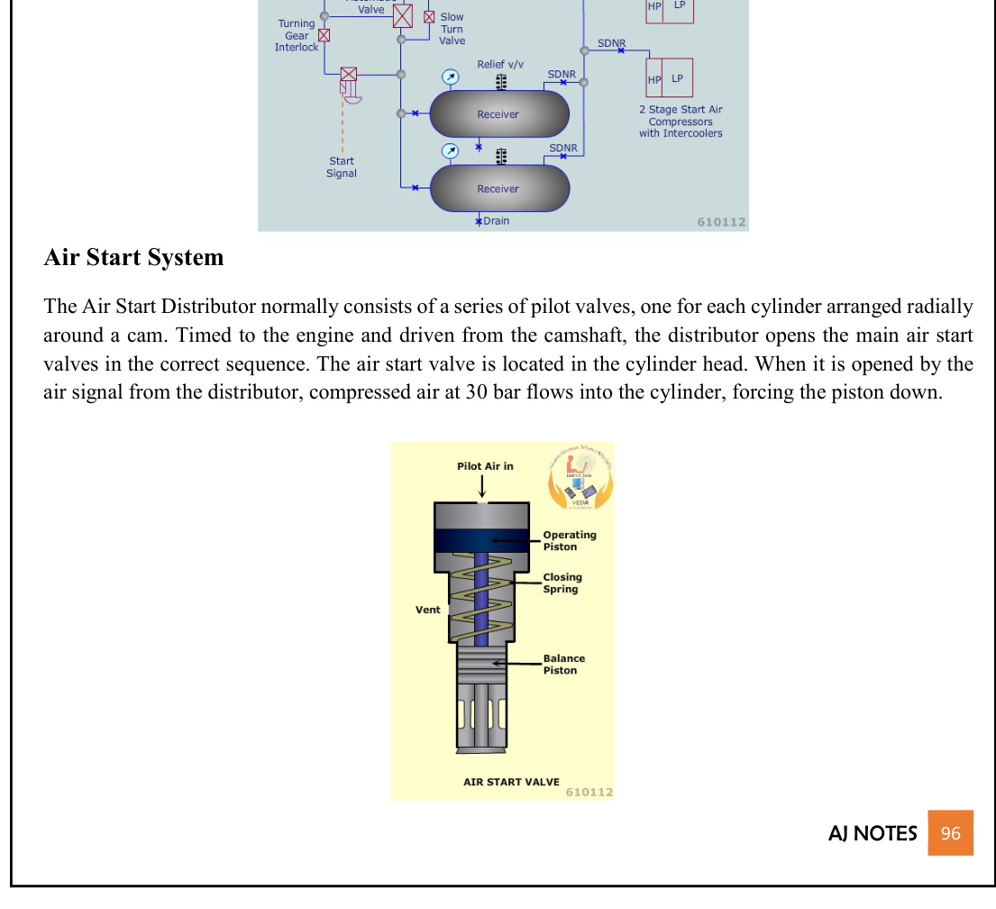
To start a large two-stroke crosshead marine diesel engine, the immense static breakaway friction of the crankshaft journals, crosshead pins, and piston ring packs must be overcome. Furthermore, the reciprocating masses must be accelerated to firing speed (typically 15 to 25 RPM) while compressing cold trapped air in the cylinders past Top Dead Center (TDC) to exceed the auto-ignition temperature of injected fuel oil.
Compressed air stored at 30 bar (3.0 MPa) is universally employed as the cranking medium. At 30 bar, compressed air stores immense potential energy capable of delivering thousands of kilowatt-hours of instantaneous expansion work directly onto the piston crowns.
SOLAS Chapter II-1 & Classification Society Rules
Because main engine starting reliability is safety-critical for ship navigation and collision avoidance, the International Convention for the Safety of Life at Sea (SOLAS Chapter II-1, Regulation 31) and classification societies (IACS UR M59) enforce rigid design mandates:
- Air Receiver Capacity:
- At least two independent main air receivers must be provided.
- For a direct reversible engine (propeller directly coupled to crankshaft without reverse gearing), the total receiver volume must be sufficient to provide at least 12 consecutive starts (alternating between Ahead and Astern) without replenishment from compressors.
- For a non-reversible engine (e.g., geared engine or controllable pitch propeller), total receiver volume must provide at least 6 consecutive starts.
- Air Compressor Capacity:
- At least two independent, power-driven starting air compressors must be installed.
- The combined capacity of the compressors must be capable of charging the air receivers from atmospheric pressure to the maximum working pressure (30 bar) in not more than 1 hour (60 minutes).
- At least one compressor must be driven independently of the main propulsion engine (electric motor driven from the main switchboard).
- An independent emergency air compressor (driven by a small diesel engine or emergency switchboard) must be provided to fill a dedicated emergency air bottle to start the emergency generator or auxiliary engines during a dead-ship recovery.
- Moisture & Oil Drainage: Each air receiver must be fitted with an internal dip pipe and bottom drain valve to facilitate the drainage of condensed water and lubricating oil carry-over. Air receivers must be blown down at every watch.
Thermodynamics of Cranking Air Expansion
When 30-bar air is admitted to a cylinder whose piston is just past TDC, it expands against the receding piston crown:
Ideal Cranking Work Done per Cylinder
W = P1 · V1 − P2 · V2 γ − 1 = P1 · V1 γ − 1 · [1 − ( V1 V2 )γ − 1]
Where P1 = 30 × 105 Pa, V1 = clearance volume at admission, V2 = cylinder volume at valve cut-off, and γ ≈ 1.4 for air.
Starting Air Valve Construction & Balanced Pneumatic Mechanics
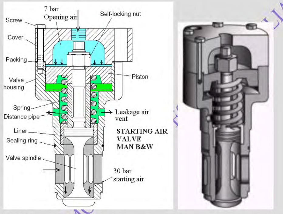
Each cylinder cover of a large marine two-stroke diesel engine houses a dedicated cylinder starting air valve. The valve must open rapidly when commanded by the distributor, admit a blast of 30-bar air, seal against combustion pressures up to 200 bar, and remain completely immune to sticking caused by soot and carbon.
1. MAN B&W Pneumatic Balanced Starting Air Valve
In the MAN B&W MC/ME design, the starting air valve is a masterpiece of pneumatic balancing:
- Pneumatic Balance Piston: Main starting air at 30 bar from the manifold enters the valve body via circumferential ports and surrounds the spindle neck. The valve spindle incorporates an integral balance piston whose cross-sectional area (Abalance) is machined to exactly match the projected seating area of the valve lid (Alid). Because the upward and downward forces exerted by the 30-bar main air cancel out perfectly (Fnet = Pair · (Abalance − Alid) = 0), main starting air cannot blow the valve open. A heavy coil spring maintains the valve firmly seated on its seat ring.
- Opening via Pilot Air: When the air start distributor sends a pilot air signal (at 30 bar or reduced 7 bar) to the top cover connection, the pilot air acts on an upper operating piston. The pilot force overcomes the return spring, snapping the valve spindle downward into the cylinder to admit main starting air.
- Closing Stroke & De-aeration: As the distributor cam rotates past the active lobe, the pilot air line vents to atmosphere. The heavy return spring snaps the valve shut. Any air that leaks past the spindle guide packing is vented through an external leakage tell-tale hole, preventing back-pressure from hindering valve closure.
- Materials of Construction: Valve housing of ductile cast iron or forged steel; valve spindle of high-tensile heat-resistant stainless steel with contact seating faces hardfaced with Stellite 6 to resist hammering and hot corrosion.
2. Sulzer Stepped-Piston Starting Air Valve
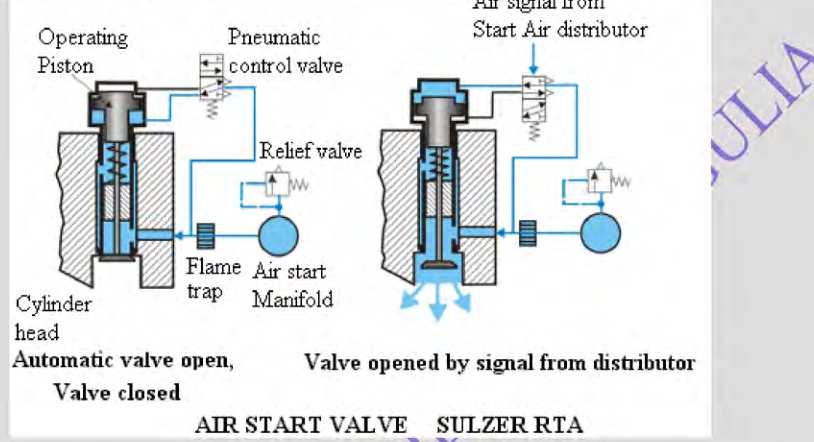
Sulzer RTA engines utilize a differential stepped-piston design:
- Differential Pressure Safety Action: The upper operating piston has two distinct diameters. Air pressure acts on both sides of the piston during service. If combustion initiates early in the cylinder and in-cylinder gas pressure rises higher than the starting air line pressure, the differential pressure acts across the stepped piston to force the valve shut even tighter!
- This positive interlocking prevents high-pressure burning combustion gas from back-blasting into the starting air manifold if the engine fires while the starting air valve is still open.
Starting Air Distributor Mechanics & Timing Overlap
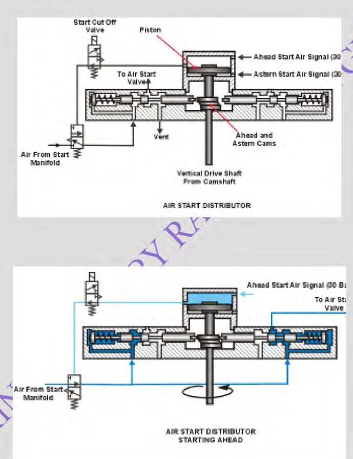
The starting air distributor acts as the pneumatic brain of the starting system. Mechanically driven from the main engine camshaft (or via an auxiliary gear train), it directs timed pilot air signals to open and shut the cylinder starting valves in exact firing sequence.
Mechanical Architecture of the Radial Distributor
In the classic radial distributor design (Sulzer and MAN B&W):
- Radial Pilot Valve Assembly: Individual spring-loaded pilot valves (one for each engine cylinder) are arranged radially in a circular housing around a central cam disc.
- Cam Disc & Profiles: The central drive shaft carries an Ahead starting cam and an Astern starting cam (or a single cam shifted axially by a reversing servomotor). The cam profile features an elevated circular lobe spanning a specific angular arc.
- Retracted Resting Position: When the engine is running on fuel or stationary in port, the pilot valve roller followers are held off the cam by internal coil springs. This eliminates mechanical friction, wear, and noise during normal sea passage.
- Engagement Stroke: When the bridge or control room initiates an engine start, control air (at 7 to 30 bar) is admitted to the distributor casing. This air pressure forces all pilot valve followers inward against their springs, bringing them into contact with the cam profile. The pilot valve whose follower rests on the cam lobe is depressed, porting pilot air to its respective cylinder starting air valve.
Starting Timing & Mandatory Angular Overlap
The timing of starting air admission must satisfy two non-negotiable thermodynamic and geometric constraints:
- Start of Admission (~2° to 5° ATDC): Air is admitted slightly after Top Dead Center. Admitting air before TDC would oppose the ascending piston, stalling the engine or causing reverse rotation!
- Cut-Off Point (~110° to 120° ATDC): The starting valve must close well before the exhaust valve opens (which occurs around 115°–125° ATDC). If the starting air valve remained open during blowdown, 30-bar starting air would blow straight out into the exhaust manifold and turbocharger turbine, wasting massive air volume and overspeeding the turbocharger.
- The Overlap Angle:
For an engine to be completely self-starting from any arbitrary crankshaft position without manual barring, at least one cylinder starting valve must always be open. Therefore, the closing point of one cylinder's starting valve must overlap the opening point of the next cylinder in the firing order:
Minimum Theoretical Valve Opening Arc for Self-Starting
Arcopen > 360° Ncylinders
For a 6-cylinder engine: 360° / 6 = 60°. Since starting valves typically remain open for ~110° (from 5° to 115° ATDC), there is a generous overlap of 50° crank angle where two cylinders receive starting air simultaneously, guaranteeing positive starting torque in all positions!
Starting Air Line Explosions: Physics, Causes & Mechanics
A starting air line explosion is one of the most violent and destructive casualties that can occur in a ship's engine room. Unlike a localized fire, an air line explosion can shatter heavy-walled steel manifolds, project lethal shrapnel across the engine platforms, and trigger major machinery space conflagrations.
The Compressed Air Fire Triangle
An explosion requires three components assembled in intimate proximity: Fuel, Oxygen, and an Ignition Source. In the starting air system, these three elements combine in a uniquely dangerous manner:
- The Oxygen: The starting air manifold contains clean air compressed to 30 bar. At 30 bar, the concentration of oxygen molecules per unit volume is 30 times higher than in atmospheric air! This immense oxygen density dramatically accelerates chemical oxidation kinetics, lowering the auto-ignition temperature of oils.
- The Fuel (Lubricating Oil Carry-Over):
- If main starting air compressors suffer from worn piston rings, defective oil scrapers, or excessive cylinder lubrication, lubricating oil vapors are discharged into the coolers.
- If compressor inter-coolers, after-coolers, and receiver automatic drains are not blown down regularly, an oil-and-water emulsion carries over into the starting air receivers and deposits along the inner bore of the main starting air manifold.
- Over months of service, this oil undergoes low-temperature oxidation, forming a sticky, carbonaceous, highly reactive film of degraded hydrocarbon sludge lining the steel pipe walls.
- The Ignition Source (The Leaking Starting Air Valve):
- This is the critical trigger. If a cylinder starting air valve jams open, binds in its guide, or fails to seat tightly due to carbon deposits on its Stellite face:
- During the combustion stroke, peak gas temperatures inside the cylinder reach 1,200°C to 1,600°C at 150+ bar.
- These incandescent, burning combustion gases blow back past the defective starting air valve directly into the starting air branch pipe!
The Detonation Wave / Shockwave Mechanism
When 1,500°C combustion gas blows back into the starting air pipe:
- The incandescent gas immediately vaporizes the oil film on the pipe walls, creating a highly flammable, stoichiometric oil mist in an atmosphere of 30-bar dense oxygen.
- The mixture ignites instantly. Because the reaction is confined inside a rigid steel pipe, the flame front accelerates rapidly from a subsonic deflagration into a supersonic detonation wave traveling down the manifold at 1,200 to 2,000 meters per second!
- Ahead of the flame front, the supersonic shockwave compresses the unburnt air-oil mixture ahead of it, driving localized pressures to 150 to 300 bar. When this shockwave impacts a closed master valve, an elbow bend, or the blind flange at the end of the air rail, the pressure reflection doubles or triples, instantly bursting the heavy steel pipe like an artillery shell!
Protective Devices: Bursting Discs, Flame Arrestors & Relief Valves
To mitigate the catastrophic consequences of a blow-back and contain potential explosions, international classification rules mandate a multi-layered defense architecture on all marine starting air installations.
1. Safety Bursting Discs & Rotatable Safety Caps
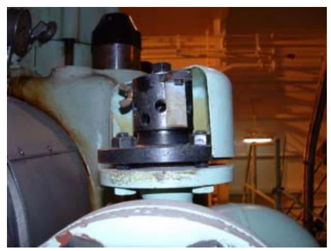
A safety bursting cap assembly is installed on each individual cylinder starting air branch pipe as close as possible to the cylinder head:
- Bursting Disc Material & Rating: The disc consists of a precision-calibrated sheet of high-purity copper or copper-coated steel clamped in a circular holder. It is engineered to rupture cleanly at approximately 100 bar (10 MPa).
- Relief Function: If burning gas blows back into the branch line, the instantaneous pressure spike ruptures the copper disc, venting the pressure wave safely into the engine room space before the flame can propagate into the main distribution rail.
- Rotatable Emergency Hood / Cap: A perforated steel safety hood encloses the bursting disc. In the event of a disc rupture while navigating in narrow channels or maneuvering:
- Escaping 30-bar air through the burst disc would completely deplete the ship's air receivers and prevent further engine starts.
- The operating engineer quickly rotates the outer hooded cap and locks it with a clamp screw. This blanks off the escape ports, isolating the blown disc and immediately restoring maneuvering air pressure until the vessel reaches a safe anchorage!
2. Manifold Spring-Loaded Relief Valves
In addition to individual bursting discs, classification rules mandate at least two spring-loaded relief valves mounted directly on the main starting air manifold (typically one at the forward end and one at the aft end):
- Setting: Calibrated to lift at approximately 35 to 40 bar (approx. 1.15 to 1.3 times normal working pressure).
- Function: Releases slow pressure accumulation caused by leaky master valves or mild combustion gas migration, protecting the manifold against over-pressurization.
3. Flame Arrestors (Quenching Elements)
A flame arrestor is interposed in the starting air branch line between the main rail and the cylinder starting valve:
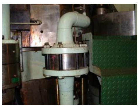
- Construction: Made of multiple layers of corrugated stainless steel or phosphor-bronze wire gauze, or a porous sintered metal matrix.
- Quenching Physics: The narrow aperture channels divide the flame front into microscopic streamlets. The immense thermal conductivity and surface area of the metal mesh absorb heat instantly, dropping the gas temperature below the auto-ignition point of oil mist, extinguishing the flame before it reaches the main manifold.
4. Automatic Starting Air Master Valve (Non-Return Function)
Mounted between the air receivers and the engine manifold, the Automatic Starting Air Valve incorporates an internal non-return check valve. If a detonation wave occurs in the engine manifold, the check valve slams shut instantly under back-pressure, making it physically impossible for an explosion to propagate upstream into the main air receivers!
Safety Interlocks, Leak Detection & Emergency Action Protocols
Engine starting is guarded by a comprehensive network of mechanical and pneumatic safety interlocks. Furthermore, early detection of a leaking start valve is the primary defense against air line explosions.
Mandatory Starting Interlocks
- Turning Gear Interlock: A mechanical microswitch and a pneumatic bleed valve operated by the turning gear engagement lever. When the turning gear is engaged, starting air is blocked and the control pilot line is vented to atmosphere, completely preventing engine starting with the turning gear engaged.
- Reversing Direction Interlock: Ensures starting air cannot be admitted until the camshaft (or electronic timing software) has fully shifted to the commanded direction (Ahead or Astern).
- Scavenge Air Pressure / Auxiliary Blower Interlock: Prevents starting if scavenge air pressure is zero or auxiliary blowers are tripped.
- Low Starting Air Pressure Lockout: Blocks starting attempts if receiver pressure falls below 15 to 18 bar, avoiding engine stall on dead centers.
In-Service Detection of Leaking Starting Air Valves
Because an air line explosion requires a leaking starting valve to provide the ignition spark, the watchkeeping engineer must verify valve tightness regularly:
- The "Hand-Touch" Temperature Test: During maneuvering and immediately after starting, the watchkeeping engineer must physically walk along the cylinder covers and touch each starting air branch pipe as close to the cylinder head as possible:
- Normal Condition: The branch pipe is cold or at ambient engine room temperature.
- Leaking Condition: The pipe feels noticeably warm or hot to the touch! This indicates hot combustion gases are leaking past the valve into the branch line.
- In-Port Static Leakage Test:
- Engage the engine turning gear and open all cylinder indicator cocks.
- Turn the engine so that the piston of the test cylinder is near mid-stroke (with scavenge ports covered).
- Open the main air bottle stop valve, isolate pilot air to the distributor, and open the automatic starting air valve manually or via test lever to pressurize the starting air manifold to 30 bar.
- Observe the indicator cocks: If compressed air hisses out of an indicator cock, that cylinder's starting air valve is leaking and must be replaced immediately!
Emergency Action if Starting Air Valve Leaks at Sea
Immediate Emergency Action Protocol
- Cut Off Fuel to Affected Cylinder: Lift the fuel pump roller follower, zero the fuel rack index, or activate the fuel puncture valve on that unit immediately to stop combustion.
- Inform the Bridge & Chief Engineer: Notify the officer of the watch that one cylinder is cut off and engine power/RPM must be reduced.
- Continuous Monitoring: Monitor starting air branch pipe temperatures and cooling water returns. Confirm the bursting cap has not blown.
- Stop Engine at Earliest Safe Opportunity: As soon as navigation permits, stop the engine, engage turning gear, isolate starting air, and replace the defective starting air valve with a certified spare.
Starting Air Troubleshooting Matrix
| Observed Fault | Probable Root Causes | Immediate Corrective Action |
|---|---|---|
| Starting air branch pipe runs hot to the touch | Cylinder starting air valve leaking, spring broken, or spindle seized in open position. | Cut off fuel to that cylinder immediately. Inform bridge and reduce load. Stop engine when safe and overhaul/replace valve. |
| Engine fails to turn on starting air |
|
Check air receiver pressure. Verify turning gear fully disengaged. Manually actuate master valve test lever. Free distributor pilot followers. |
| Safety bursting cap blows during maneuvering (loud bang) | Severe blow-back from leaking starting valve ignited oil vapor in branch pipe. | Rotate and lock the safety cap hood immediately to isolate the air leak. Cut off fuel to affected unit. Stop engine and inspect manifold. |
| Engine turns on air but fails to catch on fuel |
|
Check air pressure. Confirm fuel pump racks advance to start index. Check cylinder air venting. Verify fuel booster pressure and fuel temperature. |
Standards & sources referenced
- SOLAS: International standards for the safety of life at sea.
- Conventions index
Practise this in the question bank
- Engine Room General (motor) — 24 questions
Found a mistake, or something unclear?
Report it in a few seconds — it goes straight to the editors.
- Two-Stroke Main Engine Standby & Start Preparation: Preheating, Turning Gear, Blow-Through & Bridge Control Changeover
- Starting & Reversing the Two-Stroke
- Manoeuvring, Port Ops & Engine Vigilance
- Four-Stroke Operation — Alternator Duty
- Starting Air System Physics, Explosions & Air Distributor