
Lifeboat Davits and Davit Winches — Gravity Lowering and Two Brakes
The davit is the one piece of deck machinery that exists purely to save life, and it is designed on a principle that is the opposite of every other winch on the ship — lowering is by gravity, and the machinery's job is to slow the boat down, not to lower it.
Key Principles at a Glance 5 points
- No mechanical assistance apart from gravity is applied when lowering a lifeboat; the operator's only job is to release the winch handbrake and hold it at the off position for the whole lowering sequence.
- If the operator loses control of the brake lever, the attached weight applies the brake positively and the boat is held at any intermediate position — that is the safety principle of the whole davit.
- The main brake has two Ferodo-lined shoes with a useful life of five years or more; the centrifugal brake limits the rate of descent within 36 m/min with no control input at all.
- A ratchet arrangement ensures the drums will not reverse, so a boat part way up cannot run back if the hoisting power is lost.
- The brake test is to hold the boat and then to arrest downward movement after a limited free run — the only way to prove that the centrifugal brake is there and working.
1. What the davit has to do
No mechanical assistance is allowed when lowering a lifeboat. Gravity takes the boat down and the brake controls it. The man at the winch must hold the brake off for the whole lowering sequence, and the brake is designed so that if he lets go, the boat stops rather than falls.
Boat davits vary in design to suit the load to be handled and the layout of a ship, but the principles are common to most davits.
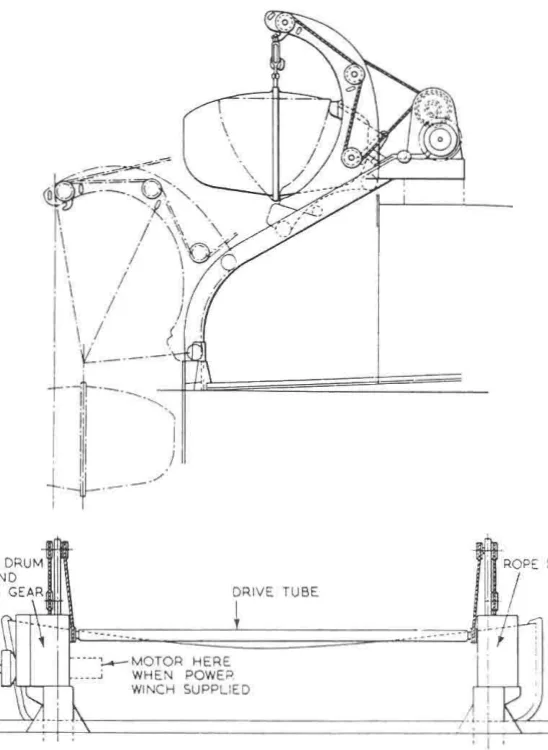
The davit has to carry the boat in its stowed position at sea, move it outboard, and lower it to the water in a controlled manner — and it has to do all of that with the ship at any angle of heel that the rules require, and with no power available, because the circumstances in which a lifeboat is launched are exactly the circumstances in which the ship's power may already be gone.
2. Lowering is by gravity alone
When lowering a lifeboat, no mechanical assistance apart from gravity is applied. The only manual function required of the operator is to release the winch handbrake and hold it at the off position during the lowering sequence.
If the operator loses control of the brake lever in difficult conditions, the attached weight will provide a positive means of application, and the boat will be held at any intermediate position. This condition applies throughout the outboard movement of the boat, from its stowed position until it is waterborne.
That is the safety principle of the whole davit. The brake is held off by hand, so the failure mode of losing grip, losing footing or being knocked over is that the brake applies and the boat stops where it is. A davit brake that had to be held on by hand would drop the boat the moment the operator let go.
3. The main brake
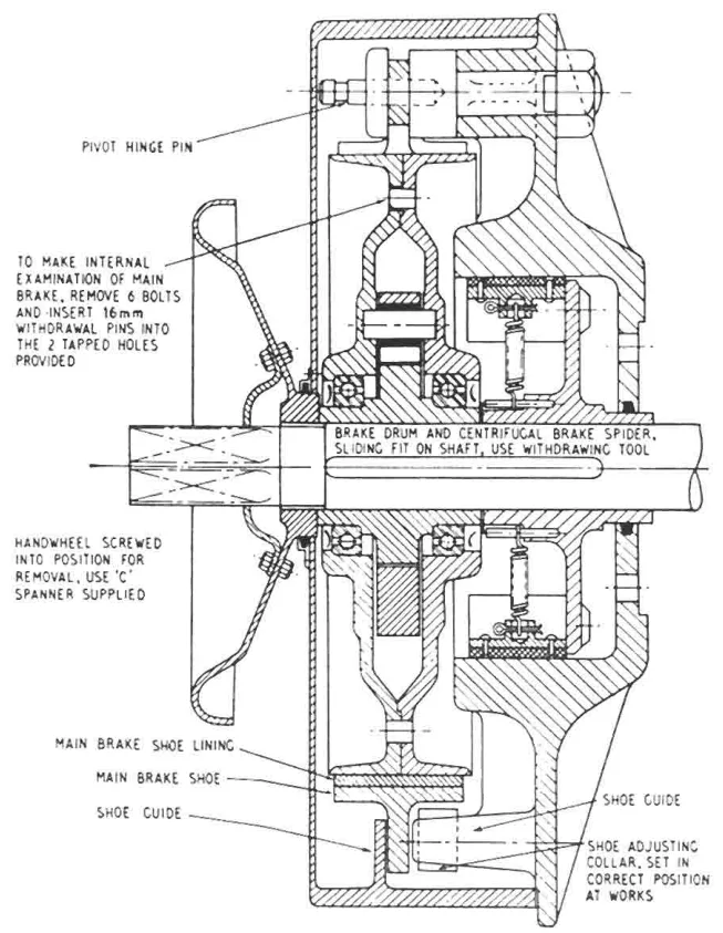
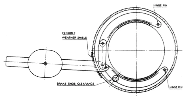
The main brake is fitted with two shoes, pivoted at one end and coupled at the other with the weighted lever, by a link. The lever projects from the casing through a watertight seal.
The shoes are Ferodo-lined and have a normal useful life of five years or more.
4. The centrifugal brake
The centrifugal brake limits the rate of descent of the boat when the handbrake is not engaged. It sits alongside the main brake on the same winch.
Shoes of calculated weight act on the inner surface of a stationary drum, being thrown out by centrifugal effect against the restraining springs. The faster the drum turns, the harder the shoes are thrown out and the more they retard it — so the brake governs the descent without any control input at all.
The lowering speed of the boat can be kept within the pre-designed limit of 36 m/min. The equivalent shipboard figure for the same duty is a controlled speed of 20 to 40 metres per minute, and the centrifugal brake is the device that keeps the boat inside it.
5. The ratchet
A ratchet arrangement ensures that the drums will not reverse, and the boat will not drop back towards the water in the event of a power failure when a boat is being hoisted.
The ratchet is a one-way device on the hoisting side of the duty. It has no effect on lowering — that is the brakes' job — but it means that a boat part way up cannot run back down if the hoisting power is lost.
6. Testing the brakes
The brakes require regular inspection for wear, and after replacement must be properly tested.
The test is defined by what the brakes have to do:
- The handbrake must be able to hold the boat, and
- it must be able to arrest downward movement after a limited free run, which is how the limiting effect of the centrifugal brake is proved.
That second test is the important one, and it is the one that is easiest to skip: releasing the brake and letting the boat run to confirm that the centrifugal brake catches it is the only way to know that the centrifugal brake is there.
7. Lifeboat engines
Where lifeboat engines are fitted, they are compression ignition engines. Both water-cooled and air-cooled engines are installed in lifeboats.
Because of their cold starting characteristics, simplicity and low maintenance requirements, air-cooled engines might be favoured for open lifeboats, but water-cooled engines are usual.
For totally enclosed lifeboats with water-cooled engines, a small single-pass heat exchanger — usually just a large bore tube — may be arranged on the outside of the lifeboat bottom, for cooling of the freshwater circuit by the sea. The heat exchanger is outside the boat because the space inside it is the boat.
8. The hydraulic cranking system
Some lifeboat engines, and the larger diesel-driven emergency generator sets, may be fitted with a hydraulic starter motor. The Startorque system is such a device: it uses an automatically charged accumulator to provide power to the hydraulic cranking motor. The accumulator is precharged with nitrogen to a pressure of 83 bar.
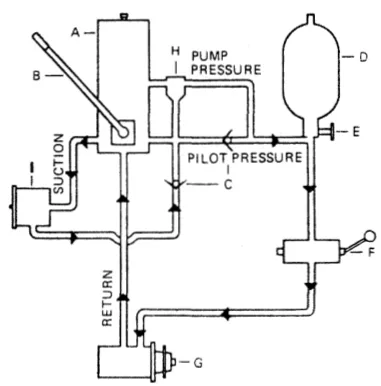
How it works.
- The system accumulator can be re-charged by a hand pump, or by an engine driven pump.
- The stored energy in the accumulator is released by a hand-operated valve, assisted by a check valve which allows a small quantity of oil to pass, enabling full engagement of the starter motor pinion with the flywheel. The valve then opens fully, allowing full flow to the hydraulic cranking motor, which generates enough torque to start the engine.
- The oil returns to the reservoir, where it is pumped back to the accumulator by either the hand pump or the engine driven pump.
- An off-loading valve protects the system from being overcharged, and spills at 20.7 bar back to the reservoir on an open circuit, maintaining flow through the re-charging pump at all times.
The unit cranks the engine at about 375 rev/min for nine revolutions, although these figures may be varied to suit particular engines by modifying the size of the accumulator.
The reason a lifeboat has a stored-energy starting system at all is the same reason the davit lowers by gravity: the boat must start when the ship's power is gone, and the accumulator is the only source of energy that is still there.