
Deck Cranes — Three Motions, Level Luffing and Safety Features
The deck crane does the same work as a pair of derricks and two winches, but does it with three motions from one machine and no rigging to prepare.
Key Principles at a Glance 5 points
- A deck crane does the work of two derricks and two winches with three motions — hoist, luff and slew — each with its own electric or hydraulic motor.
- Level luffing means the load is neither lifted nor lowered by the action of luffing the jib, so the luffing motor need only be rated to lift the jib and not the load as well.
- Heel of only 5° disturbs the level luffing geometry: on a 55 tonne crane the pull on the luffing rope is approximately doubled, and the ropes must be over-proportioned to keep the factor of safety.
- With the inclination inward and the jib near minimum radius, the jib's own weight moment may not prevent it luffing up under the resultant of the hoisting rope — only the luffing limit and the brake stand between that and an accident.
- Ward-Leonard and electro-hydraulic control are preferred to pole changing because they give continuous speed, less fierce power surges and far simpler contactors that need less maintenance.
1. Why cranes
A crane is safe because its brakes are spring applied and its limits are positive. The luffing limit in particular is not a convenience — the geometry that makes the crane lift a load level is the same geometry that can make the jib luff up on its own if the limit is overridden in the wrong direction.
A large number of ships are fitted with deck cranes. They require less time to prepare for working cargo than derricks, and have the advantage of being able to accurately place, or spot, cargo in the hold.
On container ships using ports without special container handling facilities, cranes with special container handling gear are essential.
Deck-mounted cranes for both conventional cargo handling and grabbing duties are available with lifting capacities of up to 50 tonnes.
2. The three motions
Deck cranes are required to hoist, luff and slew, and separate electric or hydraulic motors are required for each motion.
3. Level luffing and the rope system
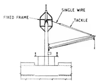
Most makes of crane incorporate a rope system to effect luffing, and this is commonly rove to give a level luff — in other words, the cable geometry is such that the load is not lifted or lowered by the action of luffing the jib, and the luffing motor need therefore only be rated to lift the jib and not the load as well.
Generally, deck cranes of this type use the Toplis three-part reeving system for the hoist rope, and the luffing ropes are rove between the jib head and the superstructure apex, which gives them an approximately constant load irrespective of the jib radius. This load depends only on the weight of the jib; the resultant of loads in the hoisting rope due to the load on the hook passes through the jib to the jib foot pin.
4. What happens when the ship heels
The level luffing geometry depends on the crane being upright, and a ship is not upright. This is the most instructive piece of crane design in the whole subject.
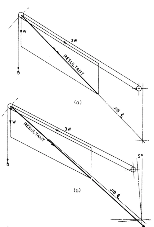
If the crane is inclined 5° in the forward direction due to heel of the ship, the level luffing geometry is disturbed and the hook load produces a considerable moment on the jib, which increases the pull on the luffing rope. In the case of a 55 tonne crane the pull under these conditions is approximately doubled, and the luffing ropes need to be over-proportioned to meet the required factor of safety.
If the inclination is in the inward direction and the jib is near minimum radius, there is a danger that the jib's own weight moment will not be sufficient to prevent it from luffing up under the action of the hoisting rope resultant. The jib is then being lifted by the load it is carrying, and only the luffing limit and the brake stand between that and an accident.
Swinging of the hook will produce similar effects to inclination of the crane.
5. Types and makers
The Stothert & Pitt 'Stevedore' electro-hydraulic crane. The jib is luffed by one or two hydraulic rams. Pilot operated leak valves in the rams ensure that the jib is supported in the event of hydraulic pressure being lost, and an automatic limiting device is incorporated which ensures that the maximum radius cannot be exceeded. When the jib is to be stowed the operator can override the limiting device. In the horizontal stowed position the cylinder rods are fully retracted into the rams, where they are protected from the weather.
Twin cranes. Some cranes are mounted in pairs on a common platform which can be rotated through 360°. The cranes can be operated independently, or locked together and operated as a twin-jib crane of double capacity, usually to give capacities of up to 50 tonnes.
6. Speeds
Most cranes can, if required, be fitted with a two-gear selection to give a choice of a faster maximum hoisting speed on less than half load.
- For a 5 tonne crane, full load maximum hoisting speeds in the range 50 to 75 m/min are available, with slewing speeds in the range 1 to 2 rev/min.
- For a 25 tonne capacity crane, maximum full load hoisting speeds in the range 20 to 25 m/min are common, with slewing speeds again in the range 1 to 2 rev/min.
- On half loads, hoisting speeds increase by two to three times.
The slewing speed is low on both, and it is the motion that decides where the load is placed. Hoisting speed is what shortens the cycle.
7. Drive mechanism and safety features
In both electric and electro-hydraulic cranes it is usual to find that the crane revolves on roller bearings. A toothed rack is formed on the periphery of the supporting seat, and a motor-driven pinion meshes with the rack to provide drive.
Spring-loaded disc or band brakes are fitted on all the drive motors. These are arranged to:
- fail safe in the event of a power or hydraulic failure, and
- operate in conjunction with motor cut-outs when the crane has reached its hoisting and luffing limits, or if slack turns occur on the hoist barrel.
The slack turns case is worth noting: if the hoist rope slackens on the barrel — because the load has touched down while the motor is still running, for example — the cut-out stops the motor and the brake applies before the rope can spool up into a tangle.
How the motions are supplied:
- In the case of electro-hydraulic cranes, it is normal for one electric motor to drive all three hydraulic pumps.
- In Ward-Leonard electric crane systems, the Ward-Leonard generator usually supplies all three drive motors.
8. Why not pole changing
Although crane motors may rely on pole-changing for speed variation, Ward-Leonard and electro-hydraulic controls are the most widely used. There are three reasons:
- Pole-change motors can only give a range of discrete speeds.
- There are less fierce power surges, since the Ward-Leonard motor, or the electric drive motor in the hydraulic system, run continuously.
- The contactors required are far simpler and need less maintenance, since they are not continuously being exposed to the high starting currents of pole-changing systems.
The third reason is the one that decides it in service. A crane is started and stopped constantly, and the contactors on a pole-changing crane are doing the hardest work on the machine.