
Electric Drives for Deck Machinery — Motors, Converters and Stalling
The electric drive is what most deck machinery uses, and the choice between the types of motor is decided almost entirely by two questions — how much torque is available at low speed, and what happens when the load overhauls the motor.
Key Principles at a Glance 5 points
- The choice of drive turns on two questions: how much torque is available at very low speed, and what happens when the load overhauls the motor.
- The d.c. motor survives on deck because it is the only production electric drive that can be designed to run stalled continuously against full rated torque — which is how a 'live motor' automatic mooring winch holds its wire.
- Ward-Leonard control and static thyristor converters both give a controllable voltage to the motor; full control needs controlled rectification and inversion with bi-directional current flow.
- The a.c. induction motor is cheap and robust but heats rapidly if stalled while energised, so an a.c. winch holds its load on the brake rather than on the motor.
- The duty picks the drive: d.c. 'live motor' for automatic mooring winches, a.c. pole change for general cargo winches, Ward-Leonard or electro-hydraulic for cranes.
1. What the drive has to do
The lowering side is the hard side. A drive that will lift a load perfectly well may be useless for lowering it under control, and that is the single most common reason for choosing one drive over another on deck.
The duty of deck machinery puts four demands on the drive which are unusual elsewhere in the engine room:
- Full torque at very low speed. A windlass heaves anchor at three to five revolutions per minute at the cable lifter, and a mooring winch takes up slack at a crawl.
- Stall without damage. A winch must be able to stall when overloaded and start again automatically when the stress is reduced, and an automatic mooring winch must hold a strain indefinitely.
- Control of an overhauling load. Lowering a suspended load is the case that separates the drives.
- Operation in the weather. The motor is on an open deck, not in a machinery space.
2. The direct current motor
The d.c. motor, although it is relatively costly and requires regular brush gear maintenance, is still used for deck machinery because it has a full speed range with good torque at any speed.
Its decisive feature is this: the d.c. motor is the only electric drive at present in production which can be designed to operate in a stalled condition continuously against its full rated torque, and that feature is used for automatic mooring winches of the 'live motor' type — the winch holds the wire by keeping the motor stalled against its rated torque rather than by relying on a brake.
The d.c. motor is also efficient, particularly in comparison with a.c. drives, when operating at speeds in the lower portion of the working range. That is where deck machinery spends most of its time.
Speeds. The majority of d.c. winch motors develop full output at speeds of the order of 500 rev/min, and where necessary are arranged to run up to two to four times this speed for light line duties. Windlass motors, on the other hand, do not normally operate with a run up in excess of 2 : 1 and usually have a full load working speed of the order of 1000 rev/min.
3. Contactor-switched resistances and the Ward-Leonard system
Control of d.c. motors by contactor-switched armature resistances was common in the days when ships' electrical supplies were d.c. It has long been replaced by a variety of Ward-Leonard type systems which give a better, more positive regulation, particularly for controlled lowering of loads. The Ward-Leonard generator is normally driven by an a.c. motor.
The Ward-Leonard arrangement is the reason the d.c. motor survives on deck: the motor itself is a fixed machine, and all the control is done in the field of the generator that feeds it, so the motor can be driven at any speed in either direction, and can be made to hold or lower an overhauling load smoothly.
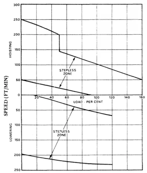
4. Static thyristor converters
Direct current motors may also be controlled by static thyristor converters which convert the a.c. supply into a variable d.c. voltage of the required magnitude for any required armature speed.
These converters must be of a type capable of controlled rectification and inversion with bi-directional current flow if full control is to be obtained. Rectification alone will drive the motor; inversion is what allows the drive to accept power back from an overhauling load, which is the lowering case again.
5. The alternating current induction motor
Alternating current induction motors, of either the wound rotor or the cage type, are also in common use.
Speed by pole changing. With these the speed may be changed by means of pole changing connections, and in the case of the wound rotor induction motor also by changing the value of the outside resistance connected in the rotor circuit.
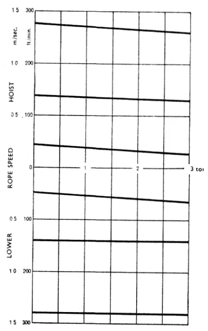
The pole change method involves the switching of high currents at medium voltage in several lines simultaneously, requiring the use of multi-pole contactors. It offers a choice of perhaps three discrete speeds such as 0.65, 0.325 and 0.1025 m/s, corresponding to 4, 8 and 24 pole operation.
The wound rotor motor is flexible when hoisting a load, because the starting resistances can be reintroduced into the rotor circuit and the load will cause the motor to slip. The slip gives a range between the speeds dictated by the pole arrangement.
The shared weakness. As with resistance-controlled d.c. motors, difficulty is experienced when providing speed control of an overhauling load — that is, lowering a suspended load. The disadvantages must be balanced against lower cost, particularly of the cage type induction motor, in comparison with the more flexible d.c. motor.
6. Voltage control — the three-phase series regulator
Another form of induction motor control system is based on the relationship between output torque and applied voltage, the torque being proportional to the voltage squared.
The controller takes the form of a three-phase series regulator with an arm in each supply line to the motor. A stable drive system can only be achieved by this means if a closed loop servo control system is used in conjunction with a very fast acting regulator which automatically adjusts the output torque to suit the load demand at the set speed. Control of an overhauling load is made possible by using injection braking techniques.
A combined system employing both these control principles can provide the full control requirements for all deck machinery.
7. Stalling and the a.c. motor
The a.c. drives described operate at the supply frequency, and consequently rapid heating of the motor will occur if the drive is stalled when energised. This is the fundamental difference from the d.c. motor, and it is why an a.c. winch cannot be used to hold a load by stalling the motor the way a 'live motor' automatic mooring winch does. The a.c. winch holds the load on its brake instead.
For the same reason, an a.c. drive needs a mechanical means of preventing the load from running back if the supply fails, and of preventing the winch from restarting when power is restored until the controller has been returned to the correct position.
8. Motor speeds and bearings
The majority of a.c. motors on deck machinery run at a maximum speed corresponding to the 4 pole synchronous speed of 1800 rev/min on a 60 Hz supply. These speeds are similar to the maximum speeds used with d.c. drives, and the bearings and shaft details tend to be much the same.
The motor bearings are normally grease lubricated. However, where the motor is flange mounted on an oil bath gearcase, the driving end bearing is open to the gearcase oil and grease lubrication is not required — a small detail, but the one that decides whether the driving end bearing is greased or not on the machine in front of you.
9. Choosing between them
The choice is not a matter of fashion. It follows from the duty:
| Duty | The demand | The drive that answers it |
|---|---|---|
| Automatic mooring winch | Hold a strain indefinitely without a brake | d.c. 'live motor', stalled continuously at rated torque |
| Cargo winch, general | Speed, fast cycle, fail-safe on power loss | a.c. pole change (now the majority), or electro-hydraulic |
| Crane | Smooth control, no fierce power surges, simple contactors | Ward-Leonard or electro-hydraulic |
| Windlass | Torque at 3–5 rev/min, run up not more than 2 : 1 | d.c. or a.c. through a high-ratio gear train |
Two general points sit behind the table. First, electro-hydraulic and d.c. electric drives offer an automatic load discrimination feature, and that is what gives them the wide speed range which shortens the cargo cycle — the actual speed and power figures are in Chapter 6 section 4. Second, the rationalisation of electrical power supply on board ship has resulted in the increased use of a.c. power, and the majority of winch machinery now produced for cargo handling uses the pole-change induction motor.