
Start-up, Raising Steam, and Shutdown
A cold boiler is steel that will grow, water that is not circulating, refractory that will crack, and a furnace that may hold gas.
Key Principles at a Glance 8 points
- Every start-up follows the same order: authorise, inspect, prove instruments, fill, vent, purge, ignite, warm, test protection, load.
- Filling must be slow and with the best water available — the water put in at start-up is the water the boiler concentrates for weeks.
- Overfilling is as bad as underfilling: it carries water into the superheater and steam line before useful steam exists.
- Never override the purge. Both the air quantity and the time must be satisfied, and a failure to complete is a fault to repair, not a timer to shorten.
- Confirm the flame twice — on the scanner and locally through the sight port — because a dirty lens, a hot refractory surface or a badly positioned scanner can all fool the system.
- Raising steam slowly is about differential expansion: a rapid start leaks tube joints, cracks stays, distorts drums and cracks refractory.
- Prove the low-water trip, flame failure trip and fuel cut-off before putting the boiler on load, and count the safety valve gags afterwards.
- Lay-up works by removing one of the three things corrosion needs — wet lay-up removes the oxygen, dry lay-up removes the water.
1. Why start-up is the most dangerous time
A boiler at steady load is a settled system. Everything is at temperature, the metal has expanded to its working dimensions, the flame is stable, and the water is circulating by itself.
A cold boiler is the opposite. It contains:
- Steel at ambient temperature, which will expand as it heats — by millimetres over the length of a drum.
- Water that is not yet circulating, because circulation depends on a temperature difference that does not exist yet.
- Refractory that will crack if heated too fast.
- A furnace full of air that may contain flammable gas from a previous imperfect shutdown.
- Protections that have not yet been proven.
Every start-up procedure exists to manage those five conditions in a controlled order. Skipping a step does not make the start faster; it removes the margin that protects the boiler when something else goes wrong.
Every start-up follows the same logical order: authorise → inspect → prove instruments → fill → vent → purge → ignite → warm → test protection → load.
3. Pre-start inspection
3.1 External inspection
Walk round the boiler and look at it as an engineer, not as a checklist:
Casing and structure
Insulation intact, cladding secure, access doors closed and dogged, no signs of hot spots or escaping gas. Corrosion or staining around doors and mountings means a leak has been running there.
Fuel system
Fuel oil line and flexible connections sound. Quick-closing valve free and correctly set. Filters clean, with differential pressure acceptable. Heater in service, with the correct steam supply or electrical supply. Burner carrier seated and clamped. No leaks at any joint.
Atomising medium
Steam or air available at the correct pressure. If steam is used, the line must be drained and warm before use — wet atomising steam produces a poor spray.
Air system
Forced-draught fan free to turn and correctly lubricated. Dampers and their actuators free through full travel. Air register vanes free. Combustion air path clear.
Gas path
Uptake and stack clear. Soot blowers returned to their parked position and their steam isolating valve shut. Any gas-side dampers in the correct position for start-up.
Furnace interior (through the sight port)
No loose refractory, no foreign objects, no obvious blockage. Burner quarl sound.
Steam line
Drains open. Expansion arrangements free. Insulation sound.
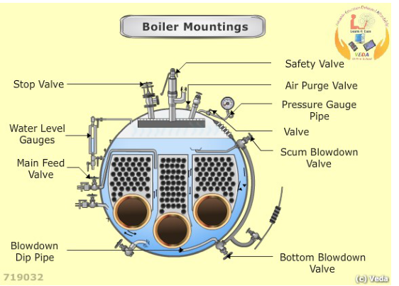
The mounting layout to confirm before lighting up: safety valves, water level indicators, water level controller, alarms and cut-out assembly, remote level transmitter, main steam outlet, feed inlet and blowdown connections. Every one of these must be in service and correctly lined up — a start-up with a mounting isolated or bypassed is a start-up without protection.
3.2 Instrument and protection check
- Both gauge glasses clean, correctly mounted, illumination working, and blown through.
- Gauge glass protection devices in place and free.
- Pressure gauge in service and reading zero.
- Feedwater control valve free through its travel; feed check valve accessible and correct.
- Feedwater supply available — tank level adequate, feed pumps ready, standby proven.
- Low-water alarm and low-low level trip available.
- Flame scanner clean, sight tube clear, and the scanner proved during the test.
- Burner management system healthy, with no unresolved lockout.
- Safety valves unobstructed, with their drains and waste steam pipes clear and easing gear free and correctly rigged.
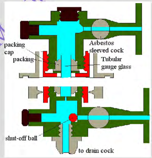
Each gauge glass has steam, water and drain cocks in gunmetal bodies, with plate guards against shattering and plugs for renewing the glass. Prove both glasses through before filling: a glass with a choked connection reads a level that the drum does not have.
3.3 Internal inspection after a repair or survey
If the boiler has been opened, before closing it up:
- Internal surfaces clean and free from scale and sludge.
- Tubes clear, proved with a light or a rod, and not plugged beyond the permitted number.
- Internal fittings, separators, and baffles correctly secured.
- Refractory sound, with expansion gaps clear.
- No tools, rags, or scaffolding material left inside.
- Manhole and handhole doors correct, with new or sound joints, correctly seated and tightened.
- All plugs and fittings fitted and tight.
A foreign object left inside a boiler becomes a tube failure, a blocked gas passage, or a shutdown at sea.
4. Filling the boiler
4.1 Water quality
Fill with the best water available — distilled or treated water, not raw water. The water put in at start-up is the water the boiler will concentrate for the next weeks. Starting with bad water means starting with a treatment problem.
4.2 Filling procedure
Confirm the correct water source and that the chemical dosing system is available.
Open the required air vents — drum vent, superheater vents, and economiser vent as fitted.
Open the gauge glass steam and water cocks; close the drain cocks.
Open the pressure gauge cock.
Open the filling line, normally through the economiser, and fill slowly.
Vent the economiser; close its vent when water issues freely.
Filling should stop with the water level just appearing in the water gauge glass, or at the level specified in the boiler procedure. Some procedures require that the level be set lower where oil-fuel cut-out devices are fitted, so fuel can pass to the burners.
Confirm the level is steady and that both gauge glasses agree.
Check for leaks at all manholes, handholes, and fittings while filling. Tighten only as the maker permits.
4.3 Why overfilling is as bad as underfilling
High water level at start-up carries water into the superheater and steam line before the boiler has produced useful steam. That produces:
- Water hammer in the superheater and steam line.
- Thermal shock to hot superheater tubes.
- Wet steam conditions during the critical warming period.
- A false high level that hides the true level during the first load increase.
Set the level accurately, and confirm it before ignition.
4.4 Why filling must be slow
Filling a large cold boiler quickly is a thermal shock in reverse. Water entering at ambient temperature into a boiler whose lower parts are at a different temperature sets up differential expansion. On a boiler that has just been closed up, that can start a leak at a joint that would otherwise have sealed.
5. Purging the furnace
5.1 What purge is for
The furnace and gas path may contain flammable gas. Sources:
- Unburnt fuel from a previous shutdown or failed start.
- Leakage past a fuel valve that does not seat properly.
- Hydrocarbon vapour from fuel oil spills or from work carried out in the furnace.
- Gas from any incomplete combustion during the last firing period.
Lighting a burner into that mixture produces a furnace explosion. Pre-purge removes the mixture before ignition is attempted.
5.2 How purge works
- The forced-draught fan runs at the correct speed for purge.
- Dampers and air register are set to the purge position so air flows through the whole gas path, not just around the burner.
- The flow must be proven — the burner management system checks the airflow signal.
- The purge runs for the full time required by the system, typically several furnace volume changes.
Both the air quantity and the time are set by the burner management system for the specific boiler. Both must be satisfied.
5.3 If purge does not complete
If the purge does not complete, find why:
- Fan not running, running at the wrong speed, or running in the wrong direction.
- Damper or air-register actuator stuck, or its position feedback faulty.
- Airflow proving device blocked or failed.
- Uptake, stack, or gas path blocked — a rag in the uptake, a broken baffle, or a closed damper elsewhere in the system.
- Purge timer or logic fault in the burner management system.
Each of these is a fault to repair. None is a reason to reduce purge time.
6. Lighting the burner
6.1 The ignition sequence
Confirm purge complete.
Confirm fuel temperature, pressure, and viscosity are at their correct values for the burner.
Confirm atomising steam or air available at the correct pressure.
Confirm the burner is correctly seated, clamped, and that its shut-off valve arrangement is correct.
Start the ignition sequence. The igniter is energised and proven first.
The fuel valve opens and fuel is admitted.
Confirm the flame by the flame scanner and locally through the sight port.
Establish stable low fire before increasing firing rate.
Watch furnace pressure, flame shape, and flue-gas temperature as the firing rate increases.
Adjust air and fuel together. Never increase one without the other.
6.2 Confirming the flame properly
The flame scanner proves the flame to the control system. The local observation proves it to you. Both are needed because the scanner can be fooled:
- A dirty lens may fail to see a good flame.
- A hot refractory surface may be seen as a flame.
- A poorly positioned scanner may lose the flame signal when the flame shape changes, even though the flame is good.
Look at the flame at every start. You are building the reference picture of a good flame for this burner, so that you can recognise a bad one later.
6.3 What a good flame looks like
- Stable, not flickering or pulsating.
- Correct shape and length for the furnace — not touching the tubes, the refractory, or the furnace floor.
- Bright, with the hottest zone in the position the design intends.
- Minimum smoke at the funnel.
- Furnace pressure steady.
6.4 If ignition fails
When the burner management system senses no flame, it must:
- Shut off the fuel immediately.
- Raise an alarm.
- Post-purge the furnace.
- Lock out until reset.
Do not attempt to relight without completing the post-purge. Each failed ignition attempt without purge adds more unburnt fuel to an already hazardous furnace.
Find the cause first:
| Cause | Check |
|---|---|
| Incomplete purge | Purge sequence completed and airflow proven |
| Weak or misplaced igniter | Electrode condition, gap, position, insulation |
| No fuel at the burner | Fuel pressure, shut-off valve, filter, line vents |
| Fuel too cold or too viscous | Heater, viscosity control, steam supply to heater |
| Water or air in fuel | Filter drains, tank drains, purifier operation |
| No atomising medium | Steam or air pressure and line drains |
| Poor spray pattern | Burner tip, swirl plate, orifice |
| Insufficient combustion air | Fan, dampers, air register |
| Wrong air-fuel mixture | Air register setting, firing rate at light-off |
| Scanner fault | Lens clean, sight tube clear, scanner function |
7. Raising steam from cold
7.1 The physical problem
As the boiler heats, every pressure part expands. The drum grows in length, diameter, and wall thickness. If the whole boiler is at the same temperature, expansion is proportional and harmless. If one part is much hotter than another, the differential expansion sets up stresses that the design did not anticipate.
The worst case is a rapid start, where the furnace and lower tubes heat quickly while the upper drum is still cool. The result is differential expansion between drum and tubes, which produces:
- Leaking expanded tube joints.
- Stay and stay-tube cracking.
- Distortion of the drum or headers.
- Refractory cracking where it is restrained.
This is why raising steam is done slowly, and why a cold start takes hours on a large water-tube boiler while a hot restart takes much less.
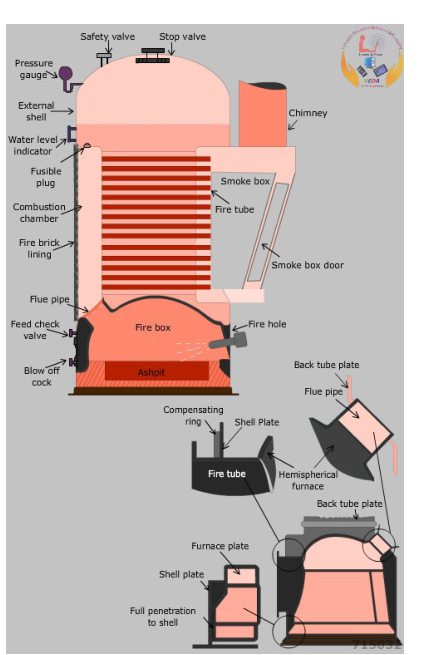
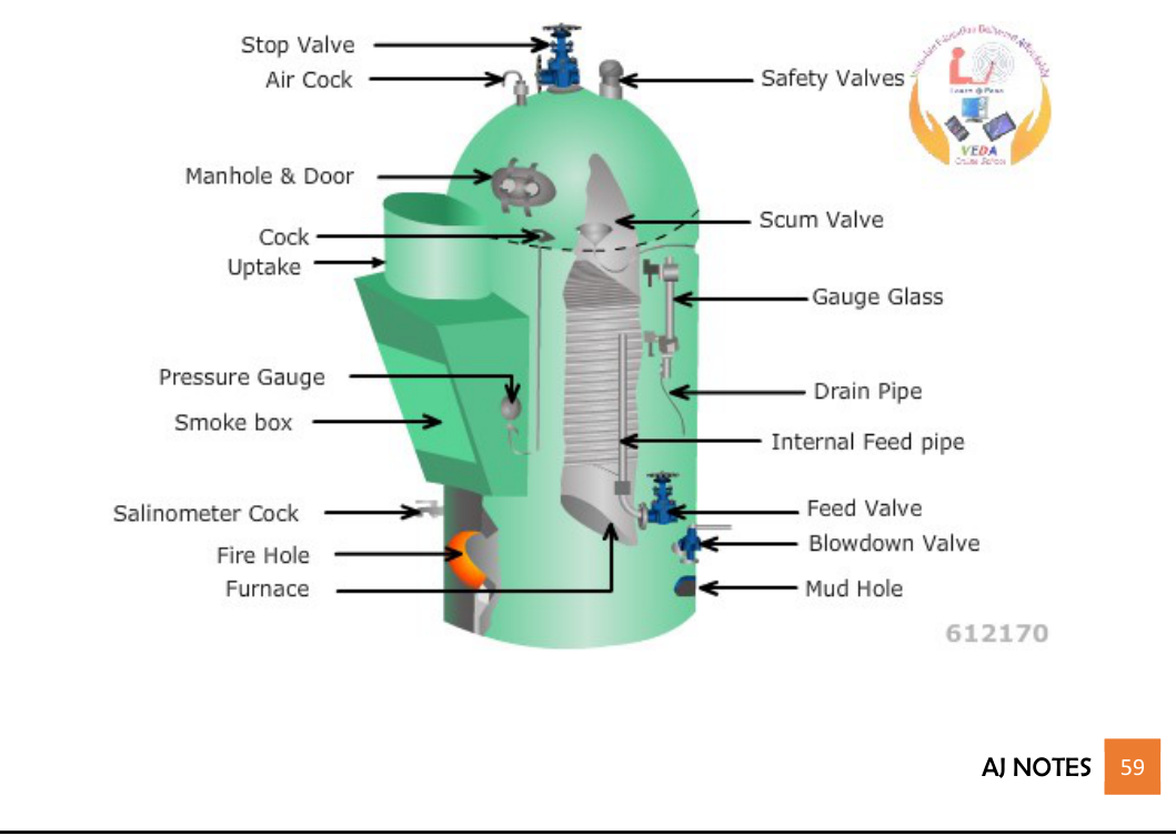
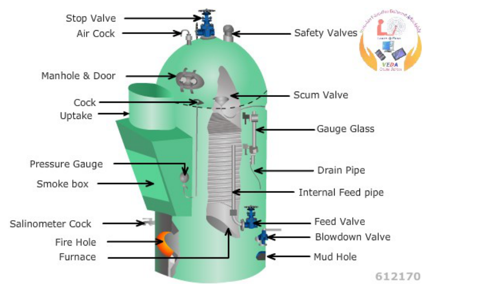
Know which boiler you are starting. A Cochran vertical fire-tube boiler (shown) holds a large volume of water around a small furnace and smoke tubes and responds slowly; a water-tube boiler holds little water in its tubes and drums and responds fast but punishes fast firing with differential expansion, leaking tube joints and cracked refractory. The warm-up rate in the procedure reflects that difference.
7.2 The sequence
Use the approved low-capacity burner. Starting at high fire dumps heat into a cold furnace faster than the structure can absorb it.
Follow the maker's pressure and time limits where a warm-up curve is provided. If no curve is provided, take as long as is practicable; a large water-tube boiler with no circulation aids may take up to 24 hours.
Raise pressure in steps. Each step lets the structure catch up with the temperature before the next increment.
Watch the gauge glass continuously. Level behaviour during warm-up tells you whether circulation has established and whether the feed control is working.
Keep superheater vents and drains open so steam flows through the superheater elements and they have cooling flow before they are exposed to high gas temperature.
Shut drum vents when steam issues forcibly from them. At that point the air has been displaced and the drum contains steam.
Keep the final superheater outlet vent open until superheated steam is being taken from the boiler, so that a steam flow is maintained through the elements.
Drain and warm the steam line before opening the main stop valve.
Watch the economiser. Steam formation in the economiser causes water hammer; it can be stopped by maintaining adequate feedwater flow and by using economiser recirculation where fitted.
Tighten manhole and handhole plugs on the first occasion of raising steam after erection or after plugs and manholes have been replaced. Wait for the temperature to stabilise before final tightening.
7.3 What happens if you raise steam too fast
- Leaking tube joints. Thermal stress opens expanded joints.
- Refractory damage. Rapid heating cracks and spalls refractory and loosens it from its anchors.
- Superheater overheating. At low steam flow with high firing, superheater tubes overheat.
- Drum level instability. Rapid changes drive the level control into oscillation, tripping the burner.
- Stress cracking in plates and stays. Repeated fast starts accumulate damage that eventually becomes a failure.
- Ogee ring and small-radius cracks. Sharp-section components with limited access are the most vulnerable to rapid heating and cooling, and to any deposits that collect in the narrow space around them.
8. Proving protection before load
The boiler must not be placed on load with unproven protection. This is the opportunity to test everything while a trip causes inconvenience rather than an incident.
8.1 Tests to perform
- Gauge glasses. Blow each glass through using the correct sequence: drain open, then water cock closed, then steam cock closed, then steam passage blown, then water passage blown, then drain closed and cocks reopened. Confirm both glasses refill correctly and agree.
- Low-water alarm and cut-out. Lower the water level by the approved method — with all burners shut off — and confirm the alarm sounds and the fuel cut-out operates.
- Flame failure shut-down. Mask the flame scanner or use the approved test method, and confirm the fuel shuts off, the alarm sounds, and the post-purge runs.
- High steam pressure cut-out where fitted.
- Fuel cut-off valve closure. Confirm the quick-closing valve actually closes and at the right time.
- Airflow and purge proving. Confirm the burner management system will not allow ignition without proven purge.
- Alarms and indications reach the engine control room, not just the local panel.
8.2 After testing
Reset everything to normal service condition. Confirm no test equipment, gag, or masking device has been left in place. Confirm the safety valves are unobstructed and their gagging gear, if used, is removed and accounted for.
A safety valve left gagged is one of the classic boiler accidents. Count the gags and the valves.
9. Steam line warming and paralleling
9.1 Warming the line
Open all steam line drains along the route.
Open the main stop valve slowly, by hand where possible, so the line warms gradually.
Watch the drains. As each section warms, its drain changes from wet to dry.
Close each drain as its section reaches temperature.
Watch for pipe movement at expansion arrangements, and for any sign of water hammer.
9.2 Why the line must be drained
A cold steam line condenses the first steam that enters it. That condensate collects at low points and in horizontal runs. When steam reaches it, the condensate is accelerated to high velocity and strikes the first obstruction it meets — a bend, a valve, or a fitting. That is water hammer, and it can crack a pipe or a support.
The drain must be open before the valve, not after.
9.3 Paralleling two boilers
Where a second boiler is to be brought on line:
Raise the incoming boiler to slightly above line pressure.
Equalise pressure through the bypass or the main stop valve, slowly.
Watch the load transfer between boilers. The incoming boiler should pick up load gradually.
Confirm both boilers settle at a stable shared load, without hunting between them.
Confirm water level control on both boilers is stable at the new load.
Instability often shows up here: two boilers with their own level control loops, connected by a common feed system, can interact through feedwater pressure fluctuations.
10. Normal shutdown
Reduce steam demand or transfer load to the other boiler, as instructed.
Reduce firing rate in steps, allowing the boiler to follow.
Maintain the water level throughout the cool-down. Do not let it fall.
Secure the fuel supply.
Allow the post-purge to complete — this clears combustible gas from the furnace and gas path in the same way as pre-purge does before ignition.
Close the main stop valve only after the burner is secured.
Drain the steam line, superheater, and economiser as directed.
Vent the boiler as instructed while it cools so that no vacuum forms. A sealed boiler that cools will draw a vacuum, and that vacuum can draw air in through any imperfect joint, which brings oxygen into a wet boiler.
Open access points only after the boiler is depressurised and cool.
Record the final readings, any defects found, and anything unusual during the run.
10.1 Emergency shutdown
- Stop firing immediately.
- Do not open furnace doors into a hot furnace; a hot furnace can admit air to unburnt fuel and cause an explosion, and it exposes personnel to flame and hot gas.
- Isolate fuel at the quick-closing valve.
- Keep the boiler vented and drained as the procedure requires.
- Maintain water level only if the condition and procedure permit. Feedwater into a boiler with overheated, uncovered tubes can cause a sudden contraction and rupture.
- Inform the duty engineer and log the event with times and indications.
- Do not restart until the cause is found and permission is given.
11. Lay-up
A boiler out of service corrodes faster than a boiler running, because the protective magnetite film needs the right chemistry and the absence of oxygen. Lay-up is a protection routine, not just a shutdown.
11.1 Choice of method
- Wet lay-up — for short to medium periods, or where the boiler must be available at short notice.
- Dry lay-up — for long periods, or where the boiler is opened for repair.
The decision depends on the duration out of service, the ambient conditions, whether the boiler will be entered, and the maker's instructions.
11.2 Wet lay-up
- Fill the boiler completely with treated water, with no air space.
- Maintain the correct chemistry — alkalinity and oxygen scavenger reserve.
- Top up periodically to replace losses and exclude air.
- Keep the water hot if the arrangement allows, because hot deoxygenated water is less corrosive than cold aerated water.
- A beneficial practice is to fit an alkaline dosing pot or a small circulation arrangement to keep the chemistry uniform.
11.3 Dry lay-up
Drain the boiler completely, including the superheater and economiser.
Dry it internally — with heater units, warm air, or by leaving the access doors open with air circulation, depending on the method chosen.
Place trays of quicklime or another desiccant inside the drums and headers.
Seal the boiler so the desiccant can absorb the remaining moisture without drawing in fresh air.
Renew the desiccant at the required interval — at least every two months.
Inspect periodically and renew the desiccant as necessary.
11.4 The principle behind both methods
Corrosion needs water, oxygen, and an electrolyte. Lay-up works by removing one of the three:
- Wet lay-up removes the oxygen, by chemical scavenging and by excluding air.
- Dry lay-up removes the water, by drying and then keeping the space dry with desiccant.
Either method is effective if applied properly and monitored. Neither works if it is set up once and forgotten.
12. Start-up and shutdown reference sequence
START-UP
1.  Authorise the start; read the log; confirm no permit or outstanding defect
2.  External inspection: casing, fuel, atomising, air, gas path, steam line
3.  Prove instruments and protections: gauge glasses, alarms, trips, scanner
4.  Internal check if the boiler has been opened
5.  Fill with treated water, slowly, through the economiser; vent all air
6.  Set the level correctly; confirm both glasses agree
7.  Purge the furnace for the full time at proven airflow
8.  Light the approved burner: prove the igniter, confirm the flame locally and on the scanner
9.  Establish stable low fire; adjust fuel and air together
10. Raise pressure in steps on the low-capacity burner
11. Keep superheater vents and drains open until steam flow is established
12. Shut drum vents when steam issues freely
13. Drain and warm the steam line before opening the stop valve
14. Prove low water trip, flame failure trip, and fuel cut-off before loading
15. Open the main stop valve slowly; parallel if required
16. Watch level, pressure, temperature, flame, furnace pressure, and uptake temperature
17. Tighten manholes and handholes as the maker permits during first warm-up
18. Log all readings and test results

SHUTDOWN
1. Reduce load, then reduce firing in steps
2. Maintain water level through cool-down
3. Secure fuel; allow post-purge to complete
4. Close the main stop valve
5. Drain steam line, superheater, and economiser as directed
6. Vent to prevent vacuum as the boiler cools
7. Cool naturally; do not force-cool
8. Open up only when depressurised and cool
9. Protect the boiler in wet or dry lay-up
10. Record readings, defects, and events