
Boiler Plant Working Flow
Five flows — water, steam, fuel, air and signal — and the failure pattern that explains almost every boiler fault.
Key Principles at a Glance 8 points
- A boiler does four jobs at once — receive water, burn fuel safely, transfer heat, deliver dry steam — and every fault shows up as a change in one of the five flows: water, steam, fuel, air and gas, or signal.
- The feedwater path exists for reasons: deaeration strips oxygen, the economiser recovers heat, and the feed check valve stops boiler water flowing back down the line.
- Circulation is a cooling function. If it slows, a steam blanket forms on the tube wall, the metal temperature climbs, and the tube bulges and ruptures — which is why the low-low level trip must never be defeated.
- The membrane water wall is gas-tight, needs no refractory between tubes, resists slagging, and carries structural load — which is why its repair is more demanding.
- Wet steam causes water hammer, erosion, deposits and corrosion; the answer is to find the cause, not to open the valve further.
- Viscosity, not temperature, is what the burner needs — too viscous gives a long smoky flame, too thin puts the flame against the quarl.
- Control has three outputs: steam pressure by firing rate, drum level by feedwater flow, steam temperature by attemperation and gas-side dampers.
- Almost every boiler fault follows one pattern: some flow changed, one indication moved first, the rest followed as consequences.
1. What a boiler actually does
A boiler is a closed pressure vessel in which water is heated until it turns into steam. That definition is simple, but it hides the four jobs that have to happen simultaneously and correctly:
Receive water — treated, at the right temperature and pressure, in the right quantity.
Burn fuel safely — atomised, mixed with the correct quantity of air, ignited, and held stable.
Transfer heat — from combustion gas into water and steam, through metal surfaces designed to take that heat.
Deliver steam — at the required pressure and temperature, dry, and at the required rate, without losing water level or safety margin.
The Marine environment makes all four harder. The boiler rolls in a seaway, so water level moves. The boiler is in a confined engine room with no natural draught. The fuel is heavy and must be heated to burn. The water has to be made on board and is never perfectly pure. And the boiler supplies steam to vital machinery, so it cannot simply be shut down when it misbehaves.
A marine auxiliary boiler is therefore designed around those constraints: a small water inventory, rapid response, forced draught, a fully water-cooled furnace, and automatic combustion control with a full set of safety trips.
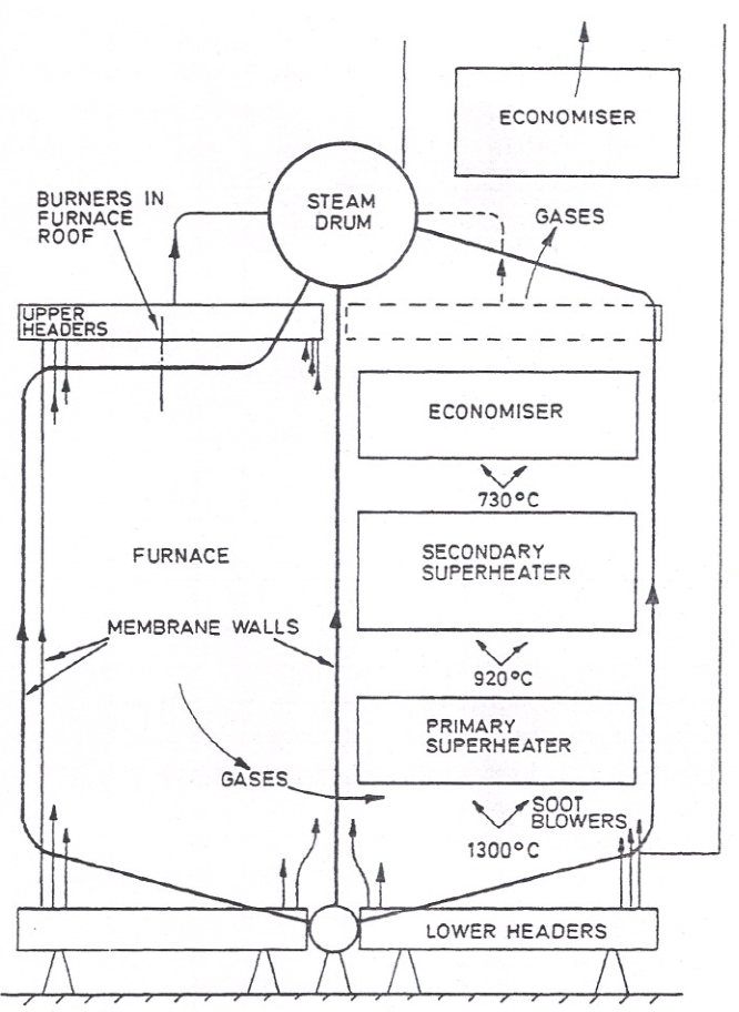
Follow the flow in that drawing from three entry points:
- Feedwater enters at low temperature on the right, passes through the economiser in the gas path, and reaches the steam drum.
- Fuel and air enter at the burner in the furnace, and burn in the water-cooled furnace.
- Combustion gas leaves the furnace, passes over superheater, generating tubes, water walls, and economiser, then out to the uptake and funnel.
Everything else in marine boiler engineering is detail on those three paths.
2. The five flows
Learn the boiler as five connected flows. When output falls or a safety condition appears, it is always because one of these has changed.
The signal flow is not an afterthought. A boiler with perfect water, fuel, and air but a dead level transmitter is unsafe and must not run.
3. Water and steam flow
3.1 The feedwater path in detail
Feedwater does not go straight from the hotwell into the boiler. Each stage in the path exists for a reason.
Hotwell / condensate tank
Collects condensate returning from steam users. The level here tells you whether the steam system is returning its water. A falling hotwell with the boiler still steaming means water is being lost — through a leak, an open drain, or a passing blowdown valve.
Condensate pump
Moves condensate forward. It is a low-pressure pump, so its suction condition matters; hot condensate at low pressure is close to flashing, and a restricted suction will cavitate it.
Feed tank or deaerator
Holds the feedwater inventory and strips dissolved oxygen. Deaeration works by heating the water to saturation and letting the oxygen come out of solution, then venting it. Oxygen removal is not optional: dissolved oxygen pits boiler tubes, and the pitting is local and deep.
Feed pump
Raises the water to a pressure higher than boiler pressure. This is why a feed pump failure is immediately serious — nothing else can push water into a pressurised vessel. Most installations have a standby pump, and the standby must be proven available, not just present.
Feed control valve
Regulates flow in response to drum level. It is the actuator at the end of the level control loop.
Feed check valve
A non-return valve. It stops boiler water and steam from flowing backwards into the feed system when the pump stops or the boiler pressure exceeds the pump discharge pressure. If it leaks, the feed line overheats and the boiler loses water back down the line.
Economiser
Uses the departing flue gas to preheat the feedwater. This is a real efficiency gain: heat that would have gone up the funnel is captured before the gas leaves.
3.2 Why the economiser can be dangerous
The economiser sits in the gas path, so it is hot on the gas side. If feedwater flow stops or falls too low, the water in the economiser tubes stops removing heat and the tubes can boil.
Two consequences follow:
- Economiser steaming — steam forms in the economiser tubes. Trapped steam causes vibration, and collapsing steam pockets cause water hammer that can crack tubes and loosen supports.
- Overheating — if flow stops altogether, the tubes overheat and can fail.
This is why economiser recirculation or bypass arrangements exist, and why the feedwater flow must be maintained even when the boiler load is low.
3.3 Circulation inside a water-tube boiler
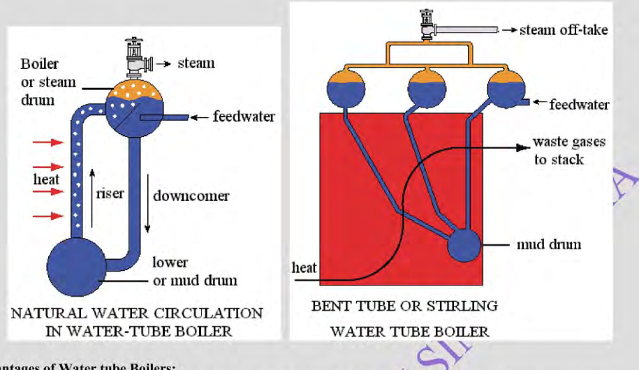
Water in a heated tube absorbs heat. When it starts to boil, the steam-water mixture is less dense than the water around it, so it rises. Cooler, denser water flows in below it to take its place. That density difference is the whole driving force of natural circulation, and it is why the arrangement is often called thermo-siphoning.
The practical path is:
Feedwater enters the steam drum.
It descends through the downcomers to the lower drum or headers.
It rises through generating tubes and water-wall tubes, absorbing heat.
The mixture returns to the steam drum as a steam-water mixture.
Steam separates from water in the drum.
Water rejoins the circulation path.
Dry steam leaves from the top of the drum.
3.4 Why circulation matters more than anything else
The metal of a heated tube is cooled only by the water on the other side of it. The heat flux at the furnace wall is very high, and steel loses strength quickly once it climbs above its design temperature.
If circulation slows, three things happen in sequence:
- The water film at the tube wall becomes a steam blanket.
- The tube wall stops transferring heat to the water and its temperature climbs.
- The metal weakens, bulges, and eventually ruptures.
That sequence can run from normal to failure in minutes on a high heat-flux tube.
Every low water level situation is therefore a cooling problem, not just a quantity problem. The tubes that are uncovered, or covered only by a slow-moving film of steam, are the tubes at risk. This is why the low-low level trip exists, and why it must never be defeated.
At higher pressure the picture gets harder. The difference in density between water and steam falls as pressure rises, so the driving head for natural circulation falls with it. That is one reason high-pressure boilers need careful design of the riser and downcomer arrangements, and why some designs use pumped circulation.
3.5 Water walls and how they are made gas-tight
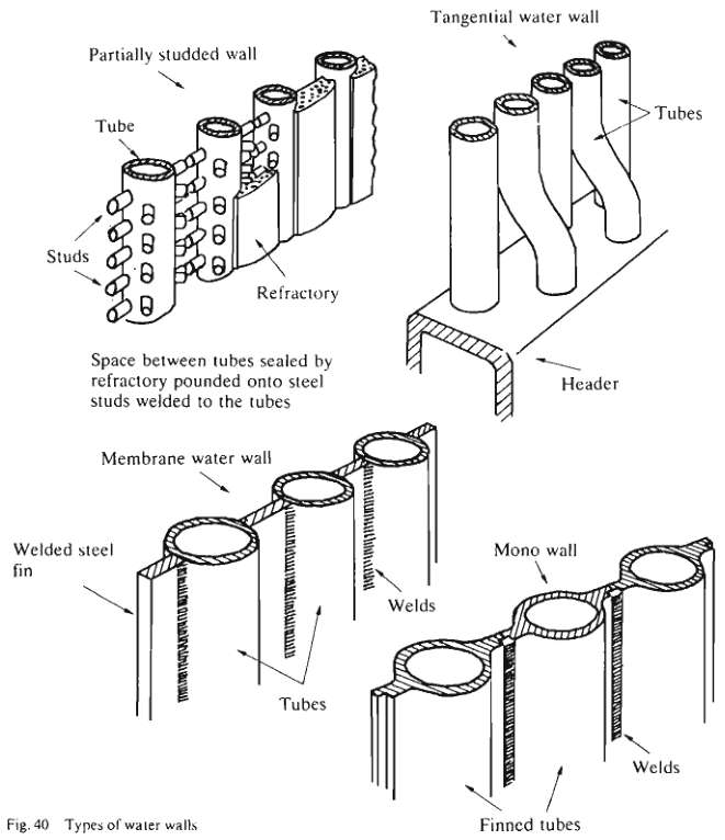
The furnace has to be cooled, and the wall that cools it has to be gas-tight. Three arrangements are used:
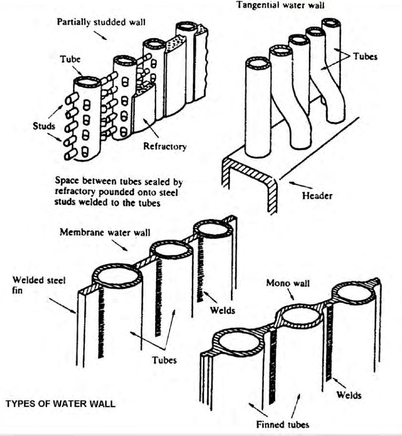
- Partially studded wall — plain tubes with steel studs welded along them. Refractory is pounded onto the studs to seal the space between the tubes. The refractory takes the heat and protects the tubes, but it adds weight, needs maintenance, and cracks.
- Membrane water wall — tubes welded to each other by a continuous steel strip, or fin, along their length. The result is a completely gas-tight, water-cooled wall with no refractory between the tubes.
- Tangential water wall — tubes set tangentially against each other to form a continuous wall.
The membrane wall is the arrangement used on modern marine radiant boilers because it eliminates the refractory between tubes:
- The furnace becomes effectively gas-tight, so there is no leakage path and no refractory to maintain.
- Only the burner quarl and a few small items still need refractory.
- Inferior fuels can be burnt without troublesome slagging of the refractory, because there is almost no refractory surface for slag to adhere to.
- The tube surface temperature is lower and more uniform, because heat is carried away by the water rather than being absorbed by a refractory layer.
The membrane also carries structural load and gives the panel its rigidity, which is why membrane wall repair is more demanding than a plain tube repair.
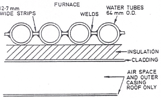
The membrane wall is welded to the drums and headers along the full length of the panel, which eliminates tube expanding and the leak path that goes with it. That is the main reason it has largely replaced the older arrangements.
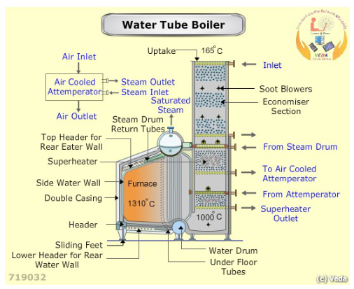
The basic two-drum water tube arrangement: the larger steam drum above the smaller water drum, with a water-cooled furnace placed between them and the tubes forming the gas path. This is the layout the rest of the gas path details are built around.
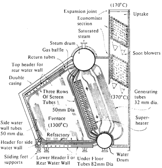
The D-type boiler wraps the gas path around the furnace, with the generating tubes, superheater, and economiser section arranged in the legs of the D. The expansion joint and uptake positions are shown.
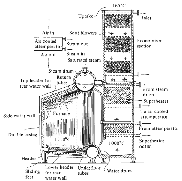
The ESD I boiler is a single-pass design with an external superheater, an air-cooled attemperator, and the top header for the rear water wall shown. Air enters cold and leaves heated, having taken heat from the steam in the attemperator.
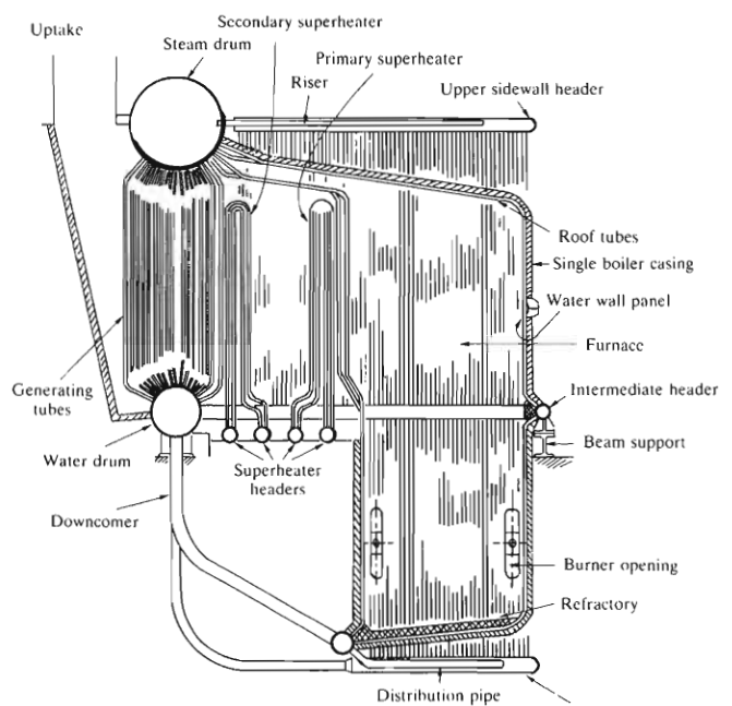
The VSM 9 shows the single-casing water tube arrangement with primary and secondary superheaters, roof tubes, distribution piping, and the lower sidewall headers. This is the layout that most clearly shows how the water wall headers feed the furnace enclosure.
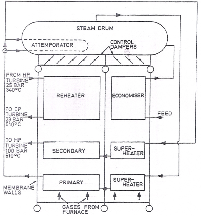
The reheat boiler line diagram shows the steam drum, primary superheater, reheater, economiser, attemperator, and control dampers. Steam returns from the HP turbine at about 25 bar and 300 °C to be reheated.
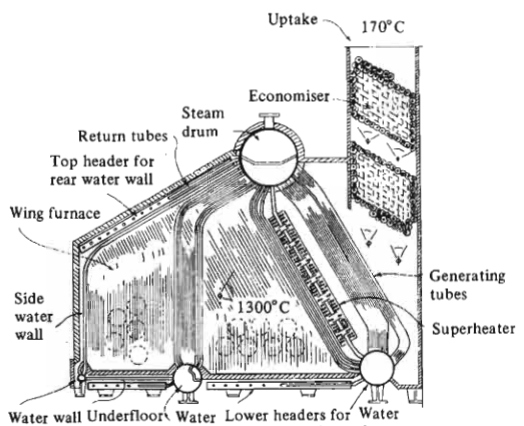
The controlled superheat boiler shows the uptake, economiser, steam drum, return tubes, top header for the rear water wall, and side water walls, with control dampers regulating gas flow over the superheater.
3.6 The steam drum and internal separation
The drum does three things:
- Gives the steam a quiet space to separate from the water.
- Stores enough water to keep the circulating flow stable through small load changes.
- Provides connection points for feedwater, downcomers, risers, and steam outlet.
Steam leaving a boiling surface always carries some water droplets. Internal separators, baffles, and driers remove the droplets before the steam leaves. The smaller and lighter the droplets, and the lower the steam velocity through the separator, the more effective that removal is.
Wet steam is dangerous because it causes:
- Water hammer — water slugs accelerate in the steam line and strike valves, bends, and turbine blades.
- Erosion — droplets at steam velocity erode turbine blading, valve seats, and pipe bends.
- Deposits — dissolved salts carried in the droplets deposit where the water evaporates, on superheater tubes and turbine blades.
- Corrosion — wet steam and the carbon dioxide and oxygen dissolved in it attack metal surfaces.
- Temperature instability — the superheater does not know whether to heat water or steam.
When steam is wet, the correct response is to find the cause, not to open the valve further. Check the drum level, the boiler water concentration, whether foaming is occurring, whether the load has changed suddenly, and whether the separators are intact.
4. Superheat and steam temperature
Saturated steam is in physical contact with the water it came from, so its temperature is fixed by its pressure. Superheated steam is heated beyond that temperature, outside the water.
The superheater takes saturated steam from the drum, passes it through tubes exposed to hot gas, and delivers superheated steam to the consumers.
4.1 Why superheat is used
- More energy per kilogram. Superheated steam carries more enthalpy than saturated steam at the same pressure, so less steam is needed for the same work.
- No condensation during expansion. Saturated steam condenses as it expands through a turbine. Superheat keeps the exhaust dry, which removes droplet erosion.
- Higher cycle efficiency. The temperature difference across the turbine increases, so a given steam flow produces more power.
- Less water hammer and less erosion in the steam piping.
4.2 The superheater's own danger
A superheater tube has gas on one side and steam on the other. It depends on steam flow for cooling. At low steam flow with full firing, the tube metal temperature rises — sometimes faster than the instruments show.
Practical consequences that follow:
- During start-up, keep the approved superheater vents and drains open so a steam flow exists through the elements.
- Do not close the drains just because pressure is rising.
- Establish flow through the superheater before exposing it to high gas temperature.
- Follow the installed boiler's start-up sequence exactly, because the correct moment to close drains is specific to the design.
Excessive steam temperature comes from:
- Low steam flow through the superheater at high firing rate.
- Too much heat in the gas path — overfiring, or fouling that has changed the heat distribution.
- Attemperator failure or control fault.
- Incorrect damper position changing the gas flow over the superheater.
- Poor water circulation reducing heat absorption elsewhere, leaving more heat for the superheater.
4.3 Attemperation
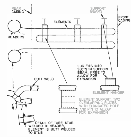
The superheater is built from elements suspended in the gas path. The element hangers and supports use overlapping plates with elongated holes and pins so the element can expand as it heats without imposing load on its supports. Elements are usually welded into headers.
Attemperation controls steam temperature by removing heat from the steam, or by cooling it, in a controlled way.
- Spray type — water is injected directly into the steam. Fast acting, but the water has to be pure or it becomes a source of deposits.
- Surface type — steam passes over cooled tubes. Slower but no water enters the steam.
- Water-cooled and air-cooled — the cooling medium is boiler water or combustion air.
Attemperation is a control loop, so it has the same failure modes as any other: sticking valve, wrong set point, failed sensor, or a control valve that has drifted. When steam temperature runs away, check the attemperator before assuming a boiler problem.
5. Fuel flow and combustion
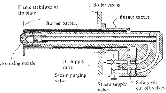
Heavy fuel oil will not burn as a liquid pool. It has to be broken into a fine spray, mixed with air, and ignited. Each stage has to work for the next to work.
5.1 The fuel path
Service tank — settles fuel and provides a steady supply.
Transfer and booster pumps — raise pressure to burner requirement.
Filters — remove particulate that would block the burner tip.
Heater — raises temperature to reduce viscosity.
Viscosity control — holds viscosity at the value the burner was designed for.
Burner shut-off valves — cut fuel positively on trip or shut down.
Burner tip — atomises the fuel.
5.2 Why viscosity is controlled, not just temperature
Viscosity is the property that actually matters. It determines how easily the fuel breaks into droplets, and how far those droplets travel into the furnace.
- Too viscous — the fuel will not atomise properly. It leaves the tip as a coarse stream, burns late and slowly, forms a long smoky flame, deposits carbon on the burner, and sends unburnt fuel up the gas path.
- Too thin — the fuel atomises too finely and the droplets do not carry far enough into the furnace. The flame sits close to the burner, the quarl overheats, and combustion is confined to a small volume.
Heating the fuel reduces viscosity, but temperature is only a proxy for viscosity. A change in fuel grade changes the temperature needed for the same viscosity, and the viscosity controller exists to keep that relationship correct as the fuel changes.
5.3 Atomisers
Six atomiser types are in marine use:
- Simple pressure jet — fuel at high pressure passes through a swirl chamber and out of a small orifice. Simple and robust; the most common type on auxiliary boilers.
- Spill type pressure jet — a return path from the swirl chamber allows the throughput to be varied without changing the atomising pressure. Better for wide load range.
- Variable orifice type — the orifice area changes with load, keeping atomisation quality at low fire.
- Steam-assisted (Y-type) — high-velocity steam shears the fuel into droplets. Used for very heavy fuel and for wide throughput range.
- Rotary cup — fuel is thrown from a spinning cup by centrifugal force. Tolerant of poorer fuel quality; suited to small auxiliary boilers, difficult to scale up.
- Pressure jet variations with different return arrangements.
The pressure jet burner is the type to know in detail:
- A steel barrel carries the assembly.
- A swirl plate imparts rotation to the fuel.
- An orifice plate controls the flow rate and final droplet size.
- A cap nut holds them in place.
- The whole unit clamps into a burner carrier in the boiler casing.
- High-pressure oil enters the angled holes in the swirl plate, rotates through the chamber, and leaves the orifice as a hollow cone of fine droplets.
The fundamental limit of the pressure jet is that one orifice has one design throughput. Turn the pressure down and atomisation degrades. This is why pressure jet burners are matched to their firing range, and why the "turn-down" for a single tip is limited.
5.4 What the burner has to achieve
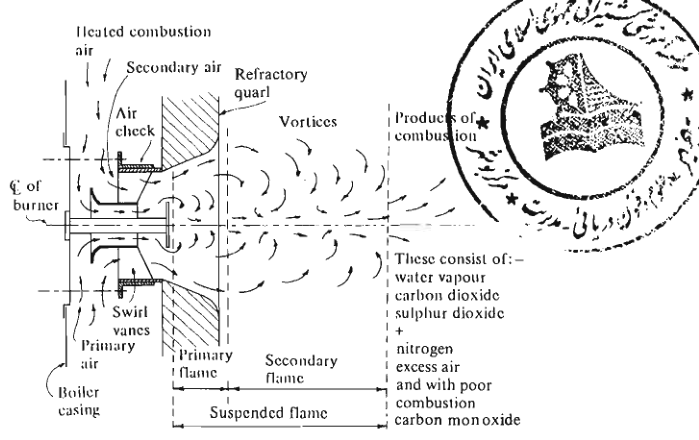
The figure shows the complete combustion arrangement: the burner at the centre, the refractory quarl shaping the flame, the swirl vanes giving rotation to the air, the secondary air entering around the burner, the air check, and the primary and secondary flame zones. The vortex pattern produced by the vanes is what holds the flame in position and mixes it with the fuel.
The oil leaves the burner as a hollow rotating cone of fine droplets. In the furnace, air is supplied as primary and secondary streams. The burner must impart enough rotational energy to the fuel to form that cone, and the air register must match the rotation so the two mix.
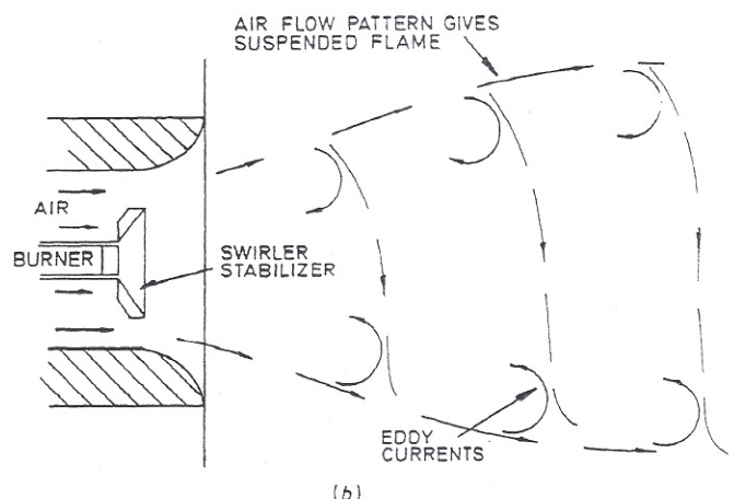
The result is a suspended flame: fuel and air enter the combustion zone at the same rate at which the products of combustion leave it, so the flame front stays in one place while the fuel passes through it. Getting that balance right is what keeps the flame stable.
For the flame to stay stable, five conditions have to hold:
The air-fuel mixture must be within the flammable range at the point of ignition.
The ignition temperature must be reached.
The mixture must have enough time at temperature to ignite.
The velocity of the air-fuel mixture must match the speed of flame propagation, otherwise the flame lifts off or flashes back.
The largest droplet must have enough residence time to burn completely before the gas cools below the point at which combustion stops.
Condition 5 is the one that produces black smoke and carbon deposits when it fails.
5.5 Common burner faults and what they look like
| Fault | Symptom |
|---|---|
| Worn or eroded orifice | Higher flow for the same pressure; long smoky flame |
| Blocked swirl plate holes | Poor spray pattern; uneven flame; carbon on tip |
| Damaged tip or leaking seat | Dribble after shut-off; carbon build-up; after-burning |
| Wrong fuel temperature | Black smoke, long flame, carbon deposits |
| Wrong fuel pressure | Weak or over-long flame depending on direction |
| Wrong burner position in carrier | Flame impingement on quarl or tubes |
| Blocked atomising steam/air passage | Coarse spray, black smoke |
| Air register set wrongly | Long flame, poor mixing, smoke, unstable flame |
6. Air and flue-gas flow
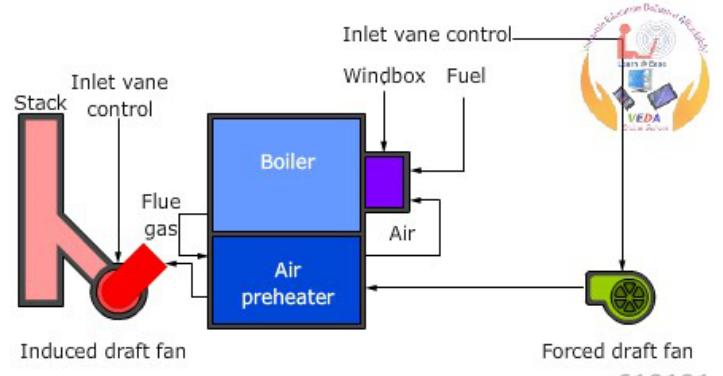
6.1 The air path
Atmospheric air enters the forced-draught fan.
Fan raises pressure slightly.
Air heater or preheater (where fitted) recovers heat from the exhaust gas.
Air register distributes the air around the burner.
Furnace — combustion takes place.
Gas path — combustion gas passes over superheater, generating tubes, water walls, and economiser.
Uptake and funnel.
6.2 Why the air quantity matters so much
Combustion is a chemical reaction needing a specific amount of oxygen. Too little air and incomplete combustion produces carbon monoxide, unburnt hydrocarbons, and soot — which is visible as black smoke, carries a MARPOL Annex VI problem, and leaves deposits that can ignite as an uptake fire.
Too much air wastes energy, because every kilogram of excess air is heated in the furnace and then thrown up the funnel. It also raises the oxygen available for corrosion and can destabilise the flame.
The aim is complete combustion with the minimum practical excess air, and that requires correct atomisation as much as correct airflow.
6.3 The air register
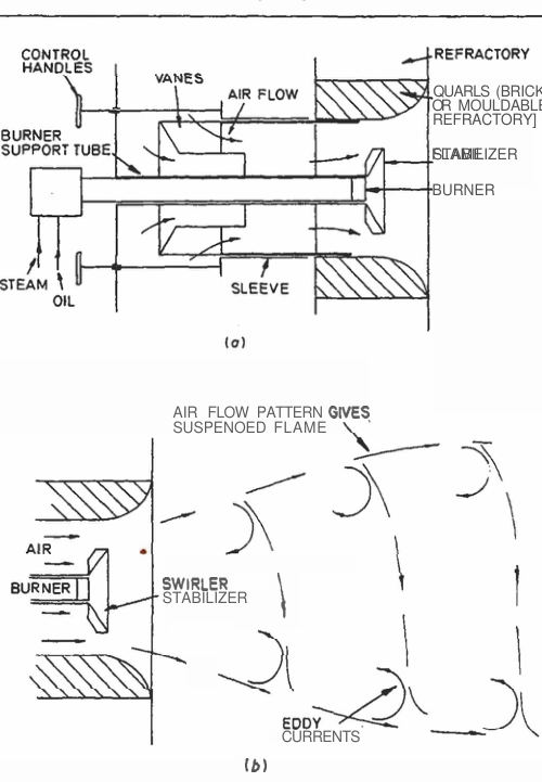
The drawing shows the register in section: the burner body and fuel supply pipe at the front, the securing screw and locating dowel, the air vanes, and the air flow pattern that produces the suspended flame. Adjustment handles are on the front for setting the vanes.
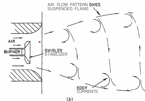
The swirl vanes rotate the air so that it forms vortices downstream of the burner. Those vortices recirculate hot gas back to the ignition zone, which is what keeps the flame lit and stable while fresh fuel-air mixture passes through it.
The refractory around the register forms the quarl that shapes the flame and protects the register from the radiant heat of the furnace.
The air register is the assembly of swirl vanes and vortex plates set into the boiler casing around the burner. It does four jobs:
- Splits combustion air into primary and secondary streams.
- Directs and mixes air with the fuel-oil spray.
- Shapes the flame to suit the furnace.
- Regulates the air quantity supplied to that individual burner.
Primary air is the smaller stream, and in rotary-cup burners it is mostly used for atomisation. It may be only around ten per cent of the total. Secondary air provides the balance of combustion air and is supplied through the register, sometimes from its own duct and fan.
The swirl vanes are designed to match the rotation of the fuel cone. If the register is changed, the mixing pattern changes, and with it the flame shape, completeness of combustion, and the amount of smoke produced.
6.4 Draught systems
Natural draught relies on the stack effect: hot gas is less dense than the outside air, so the column of hot gas in the funnel is displaced by the cooler, denser air outside it, drawing gas up the stack. The draught produced is theoretically independent of stack diameter, but in practice the diameter has to be large enough that friction does not consume the available draught. Naturally produced draught is small and is suited only to systems with small pressure losses.
Forced draught uses a fan before the boiler to push air in. The whole gas path is then above atmospheric pressure.
Induced draught uses a fan after the boiler to pull gas through. The gas path is below atmospheric pressure. Any leakage then draws air into the gas stream rather than pushing hot gas out.
Balanced draught uses both fans, with the furnace held at a slightly negative pressure. The forced draught fan supplies the air; the induced draught fan removes the gas; the balance point sets the furnace pressure.
The advantage of holding the furnace slightly negative is that any leakage at casing joints lets relatively cool combustion air leak inward, rather than letting very hot gas and flame leak outward into the casing space and engine room. That is a genuine safety benefit, not just an efficiency one.
The pressure-fired boiler is the common marine arrangement: the forced draught fan supplies all combustion air, and the furnace runs slightly positive. This demands good casing tightness, because the boiler front and burner must seal properly. Poor burner fitting or a damaged casing gasket lets hot gas escape.
Draught loss is the pressure consumed by each element in the gas path — furnace, superheater, generating bank, economiser, air heater, ducting, and stack. The total available draught has to overcome all of them, and the fan is sized for the total. When a surface fouls, its pressure loss increases, and either the flow falls or the fan has to work harder.
6.5 Diaphragms, baffles, and gas path control
Baffles direct gas across the tube surfaces and set the gas velocity. Higher velocity gives better heat transfer and keeps tubes cleaner, but increases draught loss and erosion. Fouled or damaged baffles let gas short-circuit, which raises exit gas temperature and reduces heat recovery.
Control dampers in the gas path adjust how much gas flows over particular surfaces — usually to control superheat. A damper left in the wrong position changes steam temperature and can overheat one section.
7. The control and protection system
A boiler has three controlled outputs. Everything else is measured to support those three.
| Controlled quantity | Manipulated by | Sensor |
|---|---|---|
| Steam pressure | Firing rate — fuel and air together | Steam pressure transmitter |
| Drum water level | Feedwater flow | Drum level transmitter (and steam/feed flow) |
| Steam temperature | Attemperation, gas-side dampers | Steam temperature transmitter |
The control loops do not act independently:
- An increase in firing rate raises steam generation, which changes drum level through swell.
- A change in feedwater temperature changes the heat balance and thus steam temperature.
- A change in steam demand changes pressure, level, and temperature at the same time.
This is why the operator watches the plant as a whole. Adjusting one loop while the others are out of balance produces a cascade of compensating errors.
7.1 The burner management system
The burner management system is the logic that permits, sequences, and protects combustion. It enforces the sequence, and it is not negotiable.
Typical sequence:
Pre-purge — air is passed through the furnace for the required time at the required flow, to remove any flammable mixture. The purge is proven by airflow measurement and a timer; it is not assumed from the fan running.
Ignition — the igniter is energised and proven, then the fuel valve opens.
Flame proving — the flame scanner must detect flame within the trial-for-ignition period.
Main flame establishment — the burner moves to low fire, and the firing rate is released.
Modulation — the firing rate follows the pressure controller within safe limits.
Post-purge on shutdown, to clear combustible gas from the furnace and gas path.
7.2 Why trips must not be bypassed
Each trip corresponds to an accident that has happened before.
| Trip | What it prevents |
|---|---|
| Low-low water level | Tube overheating and rupture |
| Flame failure | Furnace explosion from unburnt fuel |
| High steam pressure | Pressure-part failure |
| Loss of combustion air | Incomplete combustion and explosion risk |
| Incorrect fuel temperature or viscosity | Poor atomisation, unburnt fuel, explosion risk |
| Emergency stop | Uncontrolled operation |
A bypassed trip does not remove the hazard. It removes the warning. The hazard remains and now arrives without notice.
7.3 Instruments fail too
Every measurement can be wrong. A failed instrument produces the same reading as a real condition until you cross-check it against an independent indication.
| Reading | Cross-check |
|---|---|
| Drum level | Both gauge glasses, remote indicator, steam flow vs feedwater flow |
| Steam pressure | Local gauge, other gauges on the same system, safety valve behaviour |
| Steam temperature | Flue gas temperature, load, attemperator position |
| Flame present | Local sight port observation |
| Feedwater flow | Pump discharge pressure, drum level response |
Before acting on an abnormal reading, confirm it against a second, independent indication.
8. What happens when steam demand changes
The boiler is a dynamic system with a very effective feedback loop — but the feedback takes time, and during that time the operator sees misleading indications.
8.1 Steam demand increases
Steam leaves the drum faster than the boiler is generating it.
Drum pressure falls.
The pressure controller increases firing rate.
Fuel and air both increase; the burner management system moves them together.
The evaporation rate rises.
At the same time, the sudden drop in drum pressure causes the steam bubbles in the water to expand. The water level in the drum rises — this is swell.
A single-element level controller reads the higher level and closes the feedwater valve, exactly when more water is actually needed.
If that happens, the boiler loses water while generating at maximum rate. The swell eventually collapses, and the level falls — often to the low-level trip point.
A two- or three-element controller avoids this by taking steam flow into account, so it starts adding feedwater as soon as the demand rises rather than waiting for the level to fall.
8.2 Steam demand decreases
Steam flow falls, but the boiler is still generating at the previous rate.
Drum pressure rises.
Firing rate reduces.
The bubbles in the water collapse because the pressure has risen and the firing has dropped. The water level falls — this is shrink.
A single-element controller reads a low level and opens the feedwater valve, adding water when the boiler is actually over-filled.
When the bubbles finish collapsing, the real level appears, and it is high.
High water level then produces carryover and water hammer downstream.
8.3 The rule for level control during load changes
Confirm with:
- Both gauge glasses.
- Remote indication.
- Steam flow.
- Feedwater flow.
- Boiler pressure.
- The actual load change that is happening.
The instruments are not lying — they are reading a real, if temporary, condition. The problem is confusing the indicated level with the actual quantity of water in the drum, which during fast load changes is a different thing.
9. The generalised failure pattern
Almost every boiler fault can be traced using the same sequence:
Some flow has changed. Water, steam, fuel, air, or signal.
The measurement that changed is visible somewhere. Find which indication moved first.
The other indications follow it. They are consequences, not independent faults.
The protection acts, or should have acted if it was healthy.
The operator restores the flow or secures the boiler.
Example: a feed check valve sticks closed.
Water flow stops.
Drum level indication falls.
Feedwater pressure rises at the pump, which may give a high discharge pressure alarm.
Steam pressure falls as the boiler loses water inventory.
Low water level alarm sounds; then low-low level trip stops the burner.
Operator confirms the level, confirms the burner has tripped, and investigates the feed line — finding the check valve.
The sequence took seconds, and most of the indications were consequences. The value of knowing the pattern is that the first indication to move is usually the useful one.
10. Summary of the whole plant
| System | Critical normal condition | What happens when it fails |
|---|---|---|
| Feedwater | Continuous flow, normal temperature, correct level | Low water level, tube overheating, trip |
| Circulating water | Continuous circulation through all heated tubes | Local overheating, bulging, tube failure |
| Steam separation | Dry steam, stable level, low dissolved solids | Carryover, water hammer, downstream deposits |
| Superheater | Steam flow at all times | Tube overheating, runaway steam temperature |
| Fuel | Correct temperature, viscosity, pressure, clean tip | Black smoke, poor combustion, flame failure |
| Air and draught | Correct fuel-air ratio, stable furnace pressure | Smoke, incomplete combustion, explosion risk |
| Economiser | Continuous feedwater flow | Steaming, water hammer, tube overheating |
| Controls | Correct measured values, healthy sensor | Wrong action, unstable operation, false alarms |
| Protection | Available and proven | No warning before failure |