
Troubleshooting the Boiler
Boiler faults do not arrive as single readings — they arrive as patterns, where one indication moves first and the rest follow.
Key Principles at a Glance 8 points
- Confirm the indication is real before anything else — a blocked glass, a failed transmitter or a scanner fooled by hot refractory will make you cause exactly the damage the protection was designed to prevent.
- Contain the risk first: reduce firing, secure the burner and protect people before investigating.
- Black smoke means incomplete combustion — the fault is usually atomisation, fuel temperature or air, not the fuel itself.
- A pulsating flame can extinguish and relight repeatedly, leaving unburnt fuel and producing pressure pulses — investigate promptly.
- When the two gauge glasses disagree, prove both independently; until they agree the actual level is unknown.
- High exit gas temperature with normal firing points at the gas path, not the burner — deposit, bypassed gas, or fouled downstream surface.
- A passing blowdown valve and a feed check valve reverse-leaking both imitate a tube leak; check their individual signatures before condemning a tube.
- Never defeat an alarm or trip because it is suspected of being faulty — repair it, or remove the boiler from service.
1. The method
Boiler faults do not arrive as single readings. They arrive as patterns — one indication moves first, and the others follow as consequences.
The troubleshooting method follows that structure:
Confirm the indication is real, not an instrument fault, by checking it against an independent source.
Contain the risk. Reduce firing, secure the burner, protect people, before investigating anything.
Compare the related readings. Level, pressure, flow, temperature, and flame move together.
Find the cause before adjusting anything.
Correct the cause, not the symptom.
Prove the boiler is safe before returning to normal load.
Record the fault, the action, and the result.
The single most important step is step 1. A gauge glass can be blocked. A transmitter can fail. A scanner can be fooled by hot refractory. Acting on a false reading causes exactly the damage the real protection was designed to prevent.
2. Combustion problems
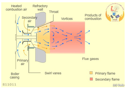
The air register splits combustion air into primary and secondary streams, gives them rotation through the swirl vanes, and mixes them with the fuel cone. The primary air carries the flame near the burner; the secondary air completes the combustion in the larger body of the flame. Most combustion faults are a failure of either the atomisation or this mixing.
2.1 Black smoke
What it means: incomplete combustion. Carbon that should have burned has left as soot.
Causes and their checks:
| Cause | Why it produces smoke | Check |
|---|---|---|
| Poor atomisation | Large droplets cannot burn in the available residence time | Burner tip, swirl plate, orifice, cap nut |
| Fuel temperature too low | Viscosity high, droplets form poorly and burn late | Heater, viscosity control, steam supply to the heater, control valve |
| Fuel pressure low | Insufficient energy to atomise | Pump condition, relief valve, filter differential, line restrictions |
| Insufficient combustion air | Not enough oxygen to burn the carbon | Fan operation, damper position, air register, air path blockage |
| Air register wrongly set | Poor mixing leaves fuel-rich zones that do not burn completely | Register position against the maker's setting |
| Burner worn or damaged | Spray pattern disturbed; inconsistent droplet size | Barrel, tip, gaskets, seating in the carrier |
| Boiler overloaded | Residence time reduced below what the droplets need | Firing rate against boiler rating; steam demand |
| Water in the fuel | Interrupts the flame locally; poor ignition of droplets | Tank drains, purifier operation, filter drains |
| Blocked or fouled gas path | Reduced combustion volume and disturbed aerodynamics | Uptake temperature, draught, gas-side condition |
| Incorrect burner position | Flame sits in the wrong place in the furnace | Burner seating and carrier alignment |
Immediate action: reduce firing, correct the cause, confirm clean combustion before increasing the load again.
Consequences if left: MARPOL Annex VI breach and possible detention; soot deposits on gas-side surfaces; rising uptake temperature; increased risk of an uptake fire; wasted fuel.
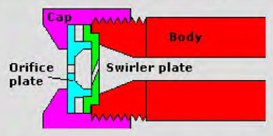
The cap, body, orifice plate, and swirler plate are the parts that control atomisation. Erosion of the orifice increases flow for the same pressure and coarsens the spray. Blockage of the swirl holes distorts the pattern. Damage to the cap or body seating causes leakage and dribble. All of these appear as smoke at the funnel before they appear as anything else.
2.2 Orange or smoky flame with high stack temperature
What it means: combustion is finishing late, in the gas path rather than in the furnace.
Causes:
- Excess fuel for the air supplied.
- Insufficient air.
- Fouled heating surfaces reducing heat absorption, so gas leaves hotter.
- Incorrect burner position, moving the flame into a cooler part of the furnace.
Check: air-fuel ratio, burner condition, gas-side cleanliness, and the burner's position in the carrier.
2.3 Unstable or pulsating flame
What it means: the flame front is not staying in one place. Either the mixture velocity is varying, or the mixture strength is varying.
Causes:
- Draught fluctuation — fan hunting, damper instability, or a furnace pressure control loop out of tune. The furnace pressure oscillates, and the flame follows it.
- Air register or damper hunting — the actuator or linkage is moving without a command, or the control loop is unstable.
- Water or air in the fuel — the fuel supply is not continuous, so the mixture strength varies.
- Fuel pressure variation — pump wear, a sticking relief valve, or an unstable heater control changing viscosity.
- Partly blocked burner tip — the spray pattern is asymmetric, so mixing varies around the flame.
- Furnace pressure control at fault — the set point is wrong, or the transmitter is faulty and the controller is chasing a false value.
Danger: a pulsating flame can extinguish and relight repeatedly. Each extinction leaves unburnt fuel, and the relight can produce a pressure pulse. Investigate promptly.
2.4 Failure to ignite
Work through the ignition sequence in order, because each step depends on the previous one:
Purge not complete. The burner management system will not permit ignition. Check airflow proving, fan, dampers, timing.
Igniter not proven. Check electrode condition, gap, position, insulation, transformer, and the igniter's own proving circuit.
Fuel not reaching the burner. Check the shut-off valve operation, fuel pressure at the burner, filters, and whether the line has been vented of air.
Fuel too cold or too viscous. Check the heater and the viscosity control. A cold burner will not light at low fire.
Atomising medium missing. Check supply pressure and confirm the line has been drained.
Burner assembly wrong. Tip, swirl plate, or orifice fitted incorrectly, or the burner not seated.
Air quantity wrong. Too much air at light-off blows the flame away; too little gives a rich mixture that will not ignite.
Lockout not reset. The burner management system may require manual reset after a fault.
2.5 Flame failure during running
What it means: a flame existed and then did not.
Causes:
- Fuel supply interrupted — pump fault, valve movement, filter blockage, or air in the line.
- Fuel temperature collapse — heater fault or steam supply loss. Viscosity rises, atomisation fails, and the flame goes out.
- Burner blockage — carbon or debris blocks the tip during running.
- Airflow or furnace pressure instability — the flame is blown out or destabilised.
- Scanner fault — the flame is fine but the scanner cannot see it. A dirty lens or a blocked sight tube produces a false flame failure.
- Flame shape moved — the flame is still burning but has moved out of the scanner's field of view.
The distinction matters: a real flame failure is a combustion problem; a false one is an instrument problem. Either way the burner trips and the furnace is purged, so the immediate consequence is the same, but the repair is different.
3. Water level problems
3.1 Low water level
| Cause | How it produces the symptom | Check |
|---|---|---|
| Feed pump fault | No flow into the boiler | Suction, filters, discharge pressure, standby pump operation |
| Feed control valve fault | Valve not opening on demand | Control signal, actuator, valve travel, strainer |
| Feed check valve fault | Flow reverse-leaks back down the feed line | Line temperature downstream of the check valve; valve condition |
| Blocked gauge passage | The glass reads a false low or responds slowly | Blow through both glasses and compare |
| Level transmitter fault | The controller sees a false high level and does not add water | Compare with direct reading |
| Tube leak | Water leaves through the leak | Feedwater flow vs steam flow; leak signs; funnel appearance |
| Blowdown passing | Continuous water loss through a leaking blowdown valve | Valve condition; drain line temperature |
| Sudden load change | Swell collapses and the true level is lower than the indication | Post-change level; load history |
| Feedwater pressure low | Valve fully open but insufficient flow | Pump discharge, system pressure |
| Hotwell level falling | No water available to feed | Hotwell level and the route back from the consumers |
Immediate action: confirm the true level, secure firing if genuinely low, do not feed into a possibly overheated boiler unless the procedure allows, find the cause.
3.2 High water level
| Cause | How | Check |
|---|---|---|
| Feed valve stuck open | Continuous feed regardless of level | Valve position and command |
| Controller set point wrong | Level is being held at the wrong value | Set point against the required level |
| Swell from load increase | Volumetric rise mistaken for a real rise | Load history; level response |
| Foaming | Froth raises the apparent level | Chemistry; oil contamination; dissolved solids |
| Transmitter reading low | Controller adds water to correct a false low | Compare with the glass |
| Operator error | Valve left open after a manual adjustment | Valve position |
Consequence: carryover. Water leaves with the steam, taking dissolved salts with it, and deposits them on superheater tubes and turbine blading. It also produces water hammer.
3.3 Level hunting
| Cause | Mechanism |
|---|---|
| Control tuning wrong | The loop over-corrects, then over-corrects back |
| Feedwater pressure fluctuation | The valve position no longer produces the expected flow, so the loop keeps correcting |
| Feed valve sticking or oversized | Oversized valve makes small corrections impossible; a sticking valve moves in steps |
| Impulse line partially blocked | The transmitter sees a delayed or damped signal, so the loop is always working on stale information |
| Insufficient pressure compensation | Steam and water density changes at different loads change the apparent flow and level |
| Multiple boilers interacting | Two level loops fighting through a common feedwater system |
| Foaming | The bubble layer makes the level move unpredictably |
3.4 Both glasses show different levels
| Cause | Check |
|---|---|
| Blocked steam or water passage on one glass | Blow through each glass individually and observe refill behaviour |
| Wrong valve position | Confirm all three cocks on each glass |
| Glass or gland leak | Visible leakage at the fitting |
| Glass wrongly mounted or fitted | Against the maker's arrangement |
Until both agree, the actual level is unknown, and the boiler should be operated conservatively with close attention to the feedwater flow and the steam flow.
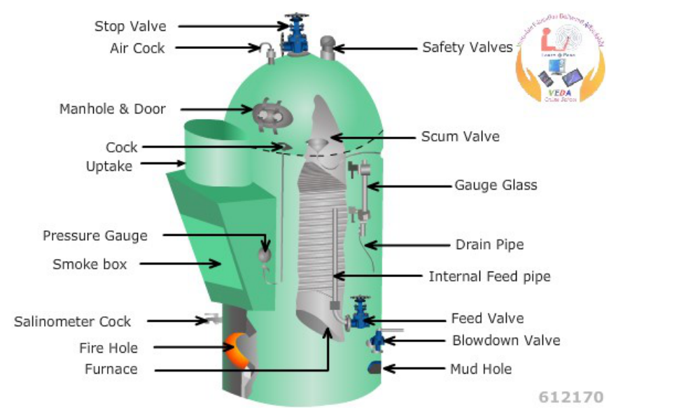
When the two glasses disagree, work through the mounting on each glass in turn: steam cock, water cock, drain cock, and the passages into the drum. The blow-through behaviour in Topic 5, section 2.2 tells you which passage is blocked.
4. Steam pressure and temperature problems
4.1 Low steam pressure
| Cause | Mechanism |
|---|---|
| Insufficient firing | The boiler is not being asked to generate enough |
| Poor combustion | Fuel is not being converted to heat efficiently |
| Fouled heating surfaces | Heat is not transferring to the water |
| Steam leak in the system | Steam is leaving before it reaches the user |
| Excessive auxiliary demand | More consumers on line than expected |
| Feedwater problem | Reduced water in the boiler reduces evaporation |
| Burner lockout on one of two burners | Half the expected heat input |
| Air leakage into the furnace | Excess air is being heated without contributing to combustion |
| Wrong fuel temperature | Poor atomisation reduces the effective heat release |
4.2 High steam pressure
| Cause | Mechanism |
|---|---|
| Firing not reducing with load | The pressure controller or its transmitter has failed |
| Sudden loss of steam demand | Pressure rises until firing catches up |
| Main stop valve throttled or closed with the boiler firing | No outlet for the steam |
| Safety valve not relieving | Pressure continues to rise past the set point |
| Pressure controller in manual with a high firing rate | Operator has left the plant on manual |
4.3 High steam temperature
| Cause | Mechanism |
|---|---|
| Low steam flow through the superheater | Less cooling for the same heat input |
| Excessive firing at low load | Heat input out of proportion to steam flow |
| Attemperator or desuperheater fault | The cooling mechanism has failed |
| Gas-side bypass or damper in the wrong position | More heat directed to the superheater |
| Fouling changing heat absorption | Heat distribution along the gas path has changed |
| Superheater tube partially blocked | Reduced flow through some elements, so they overheat locally |
| Poor water circulation | Less heat absorbed elsewhere leaves more for the superheater |
4.4 Low steam temperature
| Cause | Mechanism |
|---|---|
| Attemperator passing | Cooling water continues to enter when it should not |
| Superheater fouled | Deposits insulate the superheater, reducing heat absorption |
| Low load with low gas temperature | Not enough heat available to superheat |
| Carryover wetting the steam | Water is being evaporated in the superheater instead of steam being heated |
| Desuperheater or bypass arrangement in the wrong position | Heat is being deliberately removed |
4.5 Wet steam and carryover
Causes:
- High water level.
- High dissolved solids, particularly chlorides and sodium salts.
- High alkalinity.
- Oil contamination.
- Sudden load change.
- Damaged or displaced steam separators.
- Insufficient blowdown.
- Mechanical carryover from a damaged internal fitting.
Consequences: turbine blade erosion; superheater tube deposits; water hammer; unstable superheat; corrosion from the dissolved gases carried in the water.
Action: reduce level if high; check chemistry; increase blowdown as permitted; find the oil source if oil is present; inspect separators at the next opportunity if the problem persists with correct chemistry.
5. Water-side problems
| Symptom | Likely cause | Mechanism | Check |
|---|---|---|---|
| Hard scale on tubes | Hardness ingress, treatment ineffective | Calcium and magnesium salts precipitate on hot surfaces | Chemistry trend; make-up water quality; dosing system |
| Soft sludge accumulation | Insufficient bottom blowdown | Precipitated solids settle in low-velocity areas | Blowdown record; bottom blowdown practice |
| Pitting | Dissolved oxygen not controlled | Local oxygen attack breaks the oxide film | Deaerator performance; scavenger dose; reserve level |
| General corrosion | Low pH, carbon dioxide | The whole surface is attacked by acid | pH and alkalinity results; condensate quality |
| Caustic attack | High caustic alkalinity concentrating under deposits or in crevices | Intercrystalline cracking; metal becomes brittle | Caustic alkalinity result; deposit survey |
| Chloride attack | Seawater ingress | Chloride and magnesium chloride produce hydrochloric acid | Chloride result; condenser tightness; make-up water |
| Oil in the boiler | Contamination from a heating coil or lubricating system | Oil coats tubes, promotes overheating and foaming | Oil test; heater coil condition; coagulant dosing |
| Rising chloride | Seawater ingress | Condenser leak, primed evaporator, or untreated make-up | Compare chloride against feedwater and condensate results |
| Foaming | High solids, oil, high level | Stable froth forms on the surface | Chemistry, level, oil test |
| Water hammer in the economiser | Economiser steaming | Trapped steam collapses and water slugs accelerate | Feedwater flow and temperature; recirculation arrangement |
| Corrosion fatigue | Cyclic stress on a corroded surface | Cracks initiate at pits or grooves and propagate under stress | Deposit and crack survey at overhaul |
| Dezincification | Selective removal of zinc from brass | Fittings become weak and porous | Condition of brass fittings and tube plates |
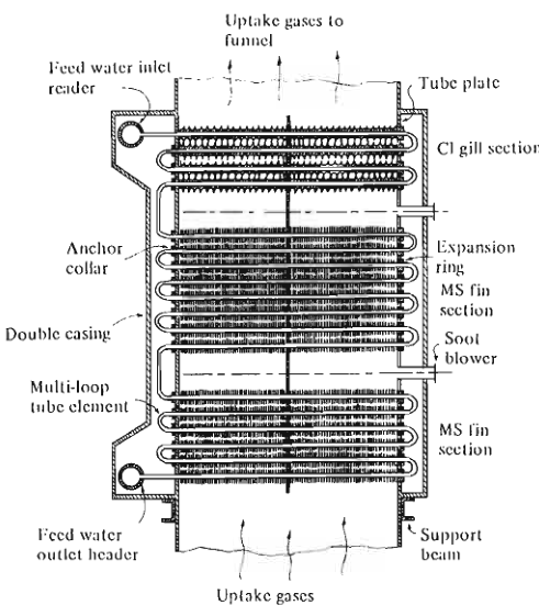
Water hammer in the economiser means this surface is steaming instead of heating water: trapped steam collapses and the water slug hammers the tubes. Check feedwater flow and temperature and the recirculation arrangement before blaming the steam line.
6. Gas-side problems
6.1 High flue-gas or uptake temperature
| Cause | Mechanism |
|---|---|
| Soot or deposit on surfaces | The deposit insulates, so less heat is absorbed |
| Damaged or missing baffles | Gas short-circuits past the surfaces it should cross |
| Incorrect air-fuel ratio | Either excess air raising the gas volume, or poor combustion raising the exit temperature |
| Overload | More gas flow than the surfaces were designed for at that temperature |
| Poor circulation | Water-side heat absorption is reduced |
| Wrong damper position or gas bypass | Gas is routed away from the surfaces |
| Air heater or economiser fouled | Downstream of the fouling, gas stays hotter |
Action: reduce load if necessary; soot blow if the deposit is soft soot; investigate baffles at the next opportunity; check air-fuel ratio.

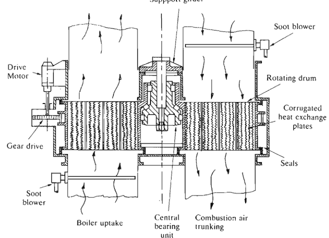
High exit temperature with normal firing points at the gas path, not the burner: deposit insulating the surfaces, a damper or baffle letting gas bypass the surfaces, or the air heater / economiser fouled so gas stays hot downstream. Compare temperatures before and after each surface to localise the fouling.
6.2 High furnace pressure
| Cause | Mechanism |
|---|---|
| Blocked or restricted uptake | Gas cannot leave as fast as it is produced |
| Damper problem | A damper is closed or partly closed when it should be open |
| Fan or draught control fault | The balance between supply and extraction is wrong |
| Excessive firing or air supply | More gas being generated than the path can carry |
| Fouled gas path | Increased resistance to flow |
| Soot-blower seal failure | Gas escaping or air entering through the wall box |
Risk: hot gas and flame escaping into the casing space and the engine room, plus the potential for casing damage. The pressure is being held in by the closed doors, and opening them releases it.
6.3 Rising gas-side differential pressure
- Soot or hard deposit build-up.
- Damaged baffles creating local restrictions.
- Refractory fragments lodged in the gas path.
- A soot blower left in the gas path.
6.4 Signs of a developing soot or uptake fire
- Uptake temperature rising rapidly, not gradually.
- Local hot spots on the casing, uptake, or stack.
- Sparks or flame visible at the stack.
- Burning smell.
Action: reduce or stop firing; do not soot blow into the fire; apply the approved smothering method; boundary cool; inspect before restart.
7. Mechanical and pressure-part problems
7.1 Tube leak
Evidence:
- Falling water level with the feedwater valve fully open.
- Feedwater flow persistently exceeding steam flow.
- Falling steam pressure and output at constant firing.
- Wet or white appearance at the funnel.
- Steam or water escaping from the casing, handholes, or around fittings.
- A leak noise inside the furnace, changing with load.
Distinguish from:
- A passing blowdown valve — check the blowdown valve and its drain line temperature.
- A feed check valve reverse-leaking — check the temperature of the feed line downstream of the check valve.
- Normal swings in level from load change.
Action: secure and isolate as instructed; cool naturally; inspect when depressurised and cool; identify the failure mechanism before repair.
7.2 Refractory damage
| Cause | Mechanism |
|---|---|
| Rapid heating or cooling | Thermal stress cracks and spalls the refractory |
| Flame impingement | Local overheating of the quarl or furnace floor |
| Fuel contamination | Ash and impurities react with the refractory surface |
| Poor anchorage | Refractory falls away from its fixings |
| Vibration | Cracking and spalling at restrained edges |
| Water or steam leakage | Thermal shock and erosion at the leak point |
Consequence: flame instability, poor combustion, hot spots on the casing, and gas leakage through the damaged area.
7.3 Support and expansion problems
- Restricted expansion causing distortion, cracking, or over-stressed nozzles.
- Corroded or loose holding-down arrangements allowing movement.
- Pipe expansion loads transferred to boiler nozzles because the pipe supports are wrong.
- Slide and roller supports seized, so the boiler cannot move as designed.
7.4 Casing and insulation corrosion
Usually found under the insulation and around mountings, manholes, handholes, and drains, where a small leak has been running. The insulation holds moisture against the steel, and the corrosion continues unseen.
Check for staining and for insulation that is damp, soft, or detached. Remove insulation locally, clean, inspect, treat, and re-protect.
8. Instrument problems versus real problems
An abnormal reading is either a real condition or a failed measurement. The two require completely different responses, and acting on the wrong one is dangerous.
| Reading | Suspect the instrument when | Suspect a real fault when |
|---|---|---|
| Low drum level | One glass reads low and the other is normal; the transmitter signal is erratic | Both glasses low; feedwater flow is high and the level still falls |
| High drum level | The remote indication is high but the glasses are normal | Both glasses high; steam appears wet; carryover signs |
| High steam pressure | Local gauge stuck; other pressure indications disagree | Safety valve lifts; other gauges agree; firing rate is high |
| Low steam pressure | One transmitter suspect; no change in firing or level | Firing rate is high for the output; steam leak signs |
| High steam temperature | Single probe suspect; no change in flue gas or flame | Flue gas temperature, load, and attemperator position all agree |
| No flame signal | Scanner lens dirty; sight tube blocked; but the furnace is clearly lit through the sight port | Fuel and air are present but the furnace is dark |
| Low feedwater flow | Positioner or transmitter faulty; pump discharge pressure normal | Pump pressure low; level actually falling |
| High flue-gas temperature | Probe or thermocouple faulty; other points normal | Multiple gas temperatures high; draught and fan load changed |
The procedure when an instrument is suspected:
Find an independent indication of the same quantity.
If the independent indication is normal, treat the suspect instrument as faulty and repair or replace it.
If no independent indication exists, operate conservatively until the measurement can be confirmed.
Never defeat an alarm or trip because it is suspected of being faulty — repair it, or remove the boiler from service.
9. Fault patterns worth memorising
Black smoke + high uptake temperature + high fan current. Fouling with poor combustion. Check burner and air-fuel ratio first; the fouling is a consequence.
Falling level + high feedwater flow + falling steam pressure. Loss of water from the system. Distinguish between a tube leak, a passing blowdown, and a feed check valve fault by checking their individual signatures.
Rising level + wet steam + unstable superheat. Carryover. Check the level first, then the chemistry, then the separators.
Level falling when steam demand rises, then tripping. Single-element level control responding to swell. The fix is in the control scheme, not in the boiler.
Steam temperature rising at low load. Insufficient steam flow through the superheater. Check the attemperator, the firing rate, and the load.
Furnace pressure rising + uptake temperature rising + fan current rising. Gas path resistance increasing. Check the uptake, dampers, soot blowers, and gas-side cleanliness.
Flame failure with a good flame visible. Scanner or sight tube problem. Clean and prove the scanner.
Safety valve lifting at correct pressure with normal firing. Pressure controller or transmitter fault, or a sudden demand loss. Check the controller before assuming the valve is wrong.
10. Quick reference
BLACK SMOKE             atomisation, fuel temperature, air, burner, register, load
FLAME UNSTABLE          draught, fuel pressure, water in fuel, burner tip, register
NO FLAME AT LIGHT-OFF   purge, igniter, fuel supply, viscosity, atomising medium
FLAME FAILS RUNNING     fuel interruption, temperature collapse, burner blockage,
                        scanner fault, draught instability

LOW LEVEL               feed pump, feed valve, check valve, leak, blowdown passing,
                        gauge blockage, transmitter, shrink after swell
HIGH LEVEL              feed valve stuck, set point, swell, foaming, transmitter
LEVEL HUNTING           tuning, feedwater pressure, valve size or sticking,
                        impulse line, density compensation
GLASSES DISAGREE        blocked steam or water passage, valve position

LOW PRESSURE            firing, combustion, fouling, leak, demand, feedwater
HIGH PRESSURE           controller, demand loss, stop valve closed, safety valve
HIGH TEMPERATURE        low steam flow, overfiring, attemperator, dampers, fouling
WET STEAM               level, solids, oil, load change, separators, blowdown

HIGH UPTAKE TEMP        soot, baffles, air-fuel ratio, overload, circulation
HIGH FURNACE PRESSURE   uptake, dampers, fan balance, firing, gas path fouling

TUBE LEAK               falling level, rising feed flow, wet exhaust, leak noise
REFRACTORY DAMAGE       rapid heating, flame impingement, contamination, anchorage
11. Recording the fault
For every fault, record:
- Time of first observation and of each action.
- The indication that moved first.
- What the other related indications were doing.
- What you checked and what you found.
- What you did, and the result.
- Who was informed.
- What remains to be done — for example, an inspection to be carried out at the next opportunity.
This record is what turns a series of unrelated breakdowns into a maintenance history, and it is what the next engineer uses to understand what happened.