

Marine Engine Vibration, Critical Speeds & Dampers
Master marine engine dynamics: torsional vibration, critical speeds, barred speed range, Geislinger and viscous dampers, axial detuners, and top bracing.
Modes of Engine & Shafting Vibration: Torsional, Axial & Transverse
A marine diesel engine coupled to a long propeller shaftline represents a complex, multi-mass elastic system subjected to violent periodic excitations. Operating this dynamic system without thorough torsional, axial, and structural vibration control results in catastrophic failures: fractured crankshafts, broken intermediate shafts, stripped reduction gears, ruined thrust bearings, and severe structural hull cracking.
The Three Co-Existing Vibration Modes
- Torsional Vibration (TV): Periodic twisting and untwisting of the crankshaft, intermediate shaft, and propeller shaft about their rotational centerlines. It generates alternating torsional shear stresses (τ) superimposed onto the mean transmission drive torque. Unlike transverse or axial vibrations, torsional vibration is completely silent and imperceptible to human senses until shaft fracture occurs!
- Axial Vibration (AV): Longitudinal back-and-forth expansion and contraction along the axis of the crankshaft and shafting. Every time a cylinder fires, peak gas pressure bends the crank throw downward, forcing the crank webs to spread outward axially. This couples torsional and axial dynamics, driving longitudinal vibration through the thrust block into the ship's double-bottom structure.
- Transverse / Lateral Structural Vibration: Lateral rocking and twisting of the entire engine block on its bedplate foundation caused by the periodic sideways thrust of the crosshead slippers against the A-frame guide bars.
Nodal Configurations and Harmonic Orders
An oscillating elastic shaftline forms stationary points of zero angular deflection called nodes, while the points of maximum oscillatory amplitude are called anti-nodes:
- One-Node Vibration (1-Node): The propeller mass oscillates in anti-phase against the combined inertia of the engine crankshaft and flywheel. The single node is located along the intermediate shafting. This mode has the lowest natural frequency (fn1) and governs low-speed resonance.
- Two-Node Vibration (2-Node): The propeller and the forward flywheel oscillate against the engine crankshaft center. Two nodes appear: one in the intermediate shaft and a second inside the engine crankshaft (typically between cylinders 4 and 6). This mode operates at a higher natural frequency (fn2) and induces destructive internal crankshaft shear stresses.
- Vibration Orders: The "order" of a vibration defines the number of complete vibrational wave cycles that occur during one single revolution of the crankshaft:
Order (n) = Vibrational Frequency (cycles/min) Engine Speed (RPM)
- Major vs Minor Critical Orders:
- Major Critical Orders: Orders that are integer multiples of the number of firing cylinders per revolution. For a 6-cylinder two-stroke engine, firing occurs 6 times per rev; thus, the 6th, 12th, and 18th orders are major criticals. At these frequencies, the harmonic torque vectors from all cylinders point in the exact same phase direction, adding arithmetically to generate immense resonance energy!
- Minor Critical Orders: Non-integer multiples (e.g., 4.5, 5.5, 7th order) where individual cylinder harmonic vectors partially cancel one another out across the firing order vector star, resulting in moderate vibratory stresses.
Resonance, Critical Speeds & The Barred Speed Range (BSR)
Every propulsion shaftline possesses discrete natural torsional frequencies (ωn) determined by its distributed polar mass moments of inertia (J) and torsional shaft stiffnesses (C):
Natural Frequency of Two-Mass Idealized System
ωn = √ C · J1 + J2 J1 · J2
Where C = torsional rigidity (G · Ip / L), J1 = engine polar inertia, and J2 = propeller polar inertia.
The Critical Speed Formula
A critical speed (Ncrit) occurs whenever the engine rotational speed causes a harmonic excitation order (n) to coincide exactly with a natural frequency of the system (fn):
Ncrit = fn (cycles per minute) Harmonic Order (n)
At this exact rotational velocity, resonance occurs. Without damping, the dynamic magnification factor (Q) escalates rapidly, multiplying vibratory shaft twist by 20 to 50 times nominal torque, quickly surpassing the fatigue endurance limit of the steel shaft.
Under-Critical vs Over-Critical Engine Layouts
| System Layout | Mechanical Characteristics | Operational Implication |
|---|---|---|
| Under-Critical Running |
|
No Barred Speed Range required. The engine operates safely across the entire speed spectrum from dead slow to full sea speed without encountering 1-node resonance. However, torque variations at MCR induce high propeller thrust variations. |
| Over-Critical Running |
|
Mandatory Barred Speed Range (BSR). Continuous operation within the resonant band is strictly prohibited. Requires vibration dampers or automated quick-passage systems. Standard layout for 5 to 12-cylinder container and bulk vessels. |
Barred Speed Range Rules & The Quick Passage Technique (QPT)
- Physical Marking & Safety Interlocks: The BSR is highlighted in bold red arc stripes on all engine room and navigation bridge tachometer dials. The electronic governor is programmed with a software lockouts that strictly prevents the speed setting from dwelling inside the barred zone.
- Continuous Running Prohibition: Continuous operation inside the BSR is illegal under Class rules. Operating within the zone causes micro-cracking at shaft keyways and oil holes, propagating into 45-degree torsional fatigue fractures.
- Quick Passage Technique (QPT): When accelerating from Slow Ahead through the BSR up to Half Ahead, the electronic governor automatically executes QPT:
- Fuel injection index is temporarily boosted to deliver maximum acceleration torque.
- On controllable pitch propeller (CPP) vessels, the propeller pitch is momentarily reduced to relieve hydrodynamic drag, allowing the engine to sweep across the barred RPM band in under 3 to 5 seconds.
- Once above the upper BSR threshold, propeller pitch and fuel rack index are restored to nominal programmed values.
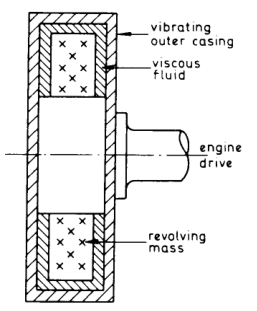
Torsional Vibration Dampers & Detuners: Geislinger vs Viscous
When altering shaft diameter, adding tuning flywheels, or adjusting cylinder firing order cannot eliminate excessive vibratory stresses, a dedicated torsional vibration damper or tuned detuner must be mounted onto the free end (fore-end) of the crankshaft.
Damping vs Detuning Physics
- Dampers (Energy Dissipators): Absorb vibrational kinetic energy and convert it irreversibly into heat through viscous fluid shear friction. They reduce the peak resonance amplitude without significantly changing the natural frequency.
- Detuners (Frequency Shifters): Feature non-linear or flexible elastic springs. As vibration amplitude increases, the spring stiffness changes dynamically, continuously shifting the natural frequency (ωn) away from the excitation frequency, preventing resonance lock-in.
1. Viscous Shear Dampers (Holset Type)
The viscous shear damper consists of a totally enclosed, hermetically welded steel annular casing directly bolted to the crankshaft fore-end flange:
- Inertia Flywheel Ring: Inside the casing floats a heavy annular steel inertia ring. Precision PTFE or bronze guide bushings maintain narrow radial and axial clearances (typically 0.25 mm to 0.50 mm) between the ring and the casing.
- Working Medium: The clearance space is completely filled with high-viscosity polydimethylsiloxane (silicone fluid), with nominal kinematic viscosities ranging from 100,000 to 500,000 cSt (roughly 500,000 times thicker than water).
- Damping Action: When the crankshaft rotates at steady velocity, the casing and inner flywheel ring rotate together in synchronism. When torsional vibrations strike the crankshaft, the casing oscillates angularly with the shaft, while the inner inertia ring resists rapid acceleration due to its massive rotational inertia. The resulting relative angular velocity shears the microscopic silicone fluid film. Viscous fluid friction dissipates the vibrational kinetic energy as heat, radiated through the outer casing surface.
- Silicone Degradation & Testing: Under millions of high-shear cycles and continuous thermal exposure (casing temperatures reach 60°C to 80°C), silicone oil undergoes molecular polymerization (cross-linking) and chain scission:
- Fluid gelation: Over-aged silicone turns into a solid rubber-like jelly, completely locking the flywheel to the casing and destroying all damping capacity!
- Sampling: A Class-mandated laboratory silicone sample must be extracted every 25,000 to 35,000 running hours via special threaded sampling plugs to evaluate viscosity deviation (scrap limit: ±25% of original viscosity).
2. Geislinger Tuned Leaf-Spring Dampers
The Geislinger damper is an advanced, high-performance mechanical-hydraulic damper/detuner widely fitted to high-powered two-stroke and medium-speed engines:
- Architecture: An inner star-shaped hub bolted to the crankshaft is linked to an outer seismic flywheel ring through radially arranged leaf spring packs made from special high-grade spring steel.
- Hydrodynamic Working Chambers: The outer ring forms enclosed oil displacement cavities between adjacent spring packs. Engine system lubricating oil is fed continuously under pressure (2.5 to 3.5 bar) through the crankshaft core into the damper chambers.
- Dual Damping Mechanism:
- Elastic Detuning: The leaf springs provide flexible torsional elasticity. Because the effective spring length shortens as the deflection increases, the spring rate is non-linear. This continuously detunes the system, preventing resonant lock.
- Hydrodynamic Viscous Damping: As relative torsional movement deflects the leaf springs, engine oil is violently squeezed from one chamber to another through narrow calibrated gaps between the springs and the casing. This hydraulic throttling provides immense viscous damping.
- Engineering Advantages over Viscous Dampers:
- Continuous lube oil flushing removes heat directly into the ship's lube oil coolers (casing will never overheat).
- No silicone fluid degradation; damping properties remain 100% constant over decades of service.
- Springs possess virtually unlimited fatigue life if oil cleanliness is maintained.
Axial Vibration Mechanics & Fore-End Hydraulic Detuners
In long-stroke, high-power two-stroke engines (e.g., stroke-to-bore ratios exceeding 3.5:1), axial vibration of the crankshaft presents a severe structural threat if left uncontrolled.
The Crank Throw Bending Phenomenon
Axial vibration is directly excited by combustion forces acting on the crank mechanisms:
- When peak firing pressure (180+ bar) acts on the piston crown, connecting rod thrust pushes the crankpin downward.
- This radial force causes the two heavy crank webs to deflect outwards (spreading apart at the bottom and pinching at the top).
- This crank web flexure forces the main journal centerlines to displace axially. Because the aft end of the crankshaft is rigidly constrained in the fore-and-aft direction by the thrust block, the cumulative deflection of all cylinders manifests as a violent axial oscillation of the free forward end.
- If the frequency of this axial excitation resonates with the zero-node natural axial frequency of the shaftline, crankshaft bending fatigue spikes and excessive thrust loads batter the thrust pads, threatening thrust collar failure.
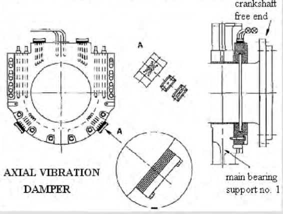
Construction of the Fore-End Hydraulic Axial Vibration Damper
Modern MAN B&W MC/ME and WinGD engines integrate a dedicated hydraulic axial vibration damper bolted directly to the forward end of the bedplate and crankshaft:
- Damping Piston: An annular steel piston is firmly bolted to the free forward end of the crankshaft and rotates with it.
- Damping Cylinder Casing: A stationary split cast-iron casing mounted to the bedplate encloses the piston, forming two hermetically sealed annular oil chambers: the Forward Chamber and the Aft Chamber.
- Hydraulic Throttling Circuit: Main engine system oil at 4.0 to 5.0 bar feeds both chambers through non-return valves. When axial vibration forces the crankshaft (and damper piston) forward, oil in the forward chamber is compressed and forced into the aft chamber through calibrated throttle orifices (orifice plugs or needle valves). When the shaft rebounds aft, the process reverses. The hydraulic throttling converts axial kinetic energy into fluid friction, dropping axial vibration amplitudes by 80% to 90%.
Axial Vibration Monitoring & Safety Alarms
Classification societies mandate continuous electronic monitoring of crankshaft axial displacement:
- Sensor Setup: Two non-contact inductive eddy-current proximity probes are mounted on the forward casing facing the free end of the crankshaft.
- Normal Vibration Level: Peak-to-peak axial displacement is typically <0.5 mm to 0.8 mm under full sea load.
- Alarm Threshold: Set at 1.2 mm to 1.5 mm. Indicates damper throttle choking, seal ring blow-by, or loss of oil supply.
- Slowdown / Shutdown Limit: Set at 2.0 mm to 2.5 mm. Triggers automated engine power reduction or emergency trip to prevent crankshaft breakage and thrust bearing wipeout!
Transverse Engine Rocking & Hydraulic Top Bracing
Large two-stroke crosshead engines stand 10 to 15 meters tall above the tank top. The alternating transverse forces exerted by the crosshead slippers against the guide shoes induce powerful lateral rocking moments that must be restrained to protect the ship's engine room structure.
H-Type vs X-Type Rocking Modes
- H-Type Vibration (Parallel Lateral Rocking): The entire upper cylinder structure rocks laterally as a rigid unit in phase from forward to aft. The engine sways port-and-starboard like an inverted pendulum at the firing order frequency.
- X-Type Vibration (Torsional Twisting Mode): The forward and aft ends of the cylinder structure move in opposite lateral directions simultaneously (forward rocks port while aft rocks starboard), forming an "X" twist pattern in top plan view. Driven by 2nd-order guide force couples.
Top Bracing Architecture
To prevent these transverse rocking modes from exciting severe resonance in the vessel's hull frames and deckhouse superstructure, top bracings are installed between the cylinder block top and the ship's hull casings.
| Bracing Type | Mechanical Arrangement | Operational Behavior |
|---|---|---|
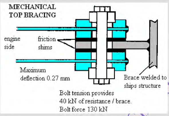
| Mechanical Friction Bracing | Stiff steel struts with interleaved friction plates clamped together by belleville spring washers and calibrated torque bolts. | Provides high stiffness against high-frequency dynamic rocking. If thermal expansion forces exceed the slipping threshold, the friction plates slide, preventing excessive static loads on the engine frame. Requires periodic re-torquing. |
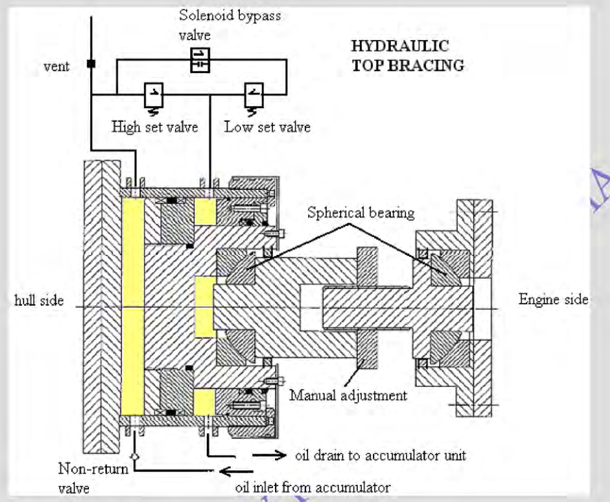
| Hydraulic Top Bracing (Modern Standard) | Hydraulic cylinder mounted on the hull frame connected to the engine cylinder block via spherical bearing joints. Plumbed to a dedicated hydraulic accumulator unit with pressure-relief valves and non-return check valves. | Dynamic Stiffener & Static Relief: Squeezing oil through restricted orifices provides high hydraulic resistance against high-frequency vibration (rocking frequency ~2–8 Hz). During slow thermal expansion or hull flexing in heavy seaways, oil bleeds through relief valves, exerting zero static bending load on the engine structure. |
Vibration Measurement, Watchkeeping & Troubleshooting Matrix
Engine dynamics must be continuously monitored through watchkeeping routines and periodic vibration surveys. Undetected damper failure leads directly to shaft fatigue failure.
Diagnostic Instrumentation & Metrology
- Laser Torsiograph Surveys: High-precision optical encoders mounted on the crankshaft free-end and the intermediate shaft measure instantaneous angular velocity variations. Software executes a Fast Fourier Transform (FFT) to break down the complex waveform into harmonic order components, confirming whether resonance stresses remain below IACS design boundaries.
- Damper Operating Temperature Checks:
- On viscous dampers, measure outer casing surface temperature using a calibrated infrared pyrometer. Normal operating temperature is typically 50°C to 75°C (due to continuous shear dissipation).
- Critical Warning: If the damper casing runs cold (ambient engine room temperature), the silicone fluid has lost its shear property or the inner ring is seized. Conversely, if temperature exceeds 90°C to 100°C, extreme torsional resonance is occurring or silicone fluid has broken down into solid gel!
- Axial Damper Oil Pressure & Float Checks: Verify that lube oil feed pressure to the axial damper remains steady at 4.0 to 5.0 bar. Check axial vibration monitor readouts daily on the main engine control console.
Vibration Failure Modes & Troubleshooting Matrix
| Observed Symptom | Probable Root Causes | Immediate Corrective Action |
|---|---|---|
| High axial vibration alarm (>1.5 mm displacement) |
|
Verify lube oil supply pressure and differential filter pressure. Check indicator power balance across all cylinders. Inspect proximity probe calibration. Overhaul damper if oil passages are choked. |
| Violent shaking of navigation bridge deckhouse at specific RPM | Resonance between engine H-type or X-type transverse rocking frequency and ship superstructure natural frequency. | Inspect hydraulic top bracing accumulator pressures and check for oil leakage. Verify that top bracing isolation valves are open. If mechanical bracing is fitted, re-torque friction plates. Adjust engine speed slightly away from resonance peak. |
| Viscous damper casing running extremely hot (>95°C) |
|
Check cylinder power balance immediately. Ensure engine speed is well clear of BSR. Extract silicone fluid sample for laboratory viscosity testing; replace damper if fluid is polymerized. |
| Rattling or metallic knocking at forward crankshaft end |
|
Stop engine immediately. Open crankcase forward door and inspect damper casing and bolts. Check oil supply filter for steel/bronze particles. |
Found a mistake, or something unclear?
Report it in a few seconds — it goes straight to the editors.