

Air Compressor Troubleshooting — Interstage Pressure & Fault Finding
Interstage-pressure master diagnostic (rise = HP suction leak/ring blow-by, drop = LP suction/delivery fault), PV card valve-leak patterns, capacity-l
1. Operational Monitoring & Interstage Pressure Diagnostics
In watchkeeping and marine examinations, the Interstage Pressure Gauge is regarded as the single most informative diagnostic instrument on the entire air compressor. Under normal running conditions, the interstage pressure remains rock-solid at its design value (e.g. 4.5 to 5.0 bar gauge).
Any deviation—whether rising or falling—pinpoints the exact cylinder, valve, or component that has failed without having to dismantle the machine.
A. Diagnostic Decision Logic
| Interstage Pressure Reading | Underlying Defect / Component Failure | Thermodynamic Explanation & Secondary Symptoms |
|---|---|---|
| ABNORMALLY HIGH (> 6.0 bar gauge / LP relief valve lifting) |
1. HP Suction Valve Leaking or Broken | The HP cylinder is unable to draw in its full charge of air from the intercooler because compressed air leaks back into the suction line during the HP compression stroke. Compressed air backs up into the intercooler, causing interstage pressure to soar until the LP safety valve lifts. |
| 2. HP Piston Rings Worn or Broken | High-pressure air slips past the HP rings down into the crankcase or back into the stepped suction space. The HP cylinder loses pumping capacity, causing air to accumulate in the intercooler. | |
| 3. Intercooler Outlet / HP Suction Line Blocked | A choked filter screen or carbon accumulation at the HP cylinder entrance restricts air flow into the HP stage. | |
| ABNORMALLY LOW (< 3.0 bar gauge) |
1. LP Suction Filter Choked | Severe restriction at the intake prevents ambient air from entering the LP cylinder. The LP stage draws a high vacuum, starving the entire compressor and dropping interstage delivery pressure. |
| 2. LP Suction Valve Leaking / Broken | During the LP compression stroke, air escapes back out through the defective suction valve into the intake filter rather than being forced into the intercooler. | |
| 3. LP Delivery Valve Leaking / Broken | Air in the intercooler rushes back into the LP cylinder during its downward suction stroke. The LP stage merely churns the same air back and forth, losing mass delivery. | |
| 4. Intercooler Drain Valve Stuck Open / Ruptured Bursting Disc | Air delivered by the LP stage is leaking out through an unseated moisture drain valve, broken drain pipe, or blown cooler tube directly into the cooling water or bilge. |
B. Classic Watchkeeping Exam Scenario: The LP Relief Valve Blows
Warning: Emergency Watchkeeping Drill
Scenario: You are on watch in the engine room. Suddenly, the LP relief valve on Main Air Compressor No. 1 begins blowing violently with a deafening roar, spewing air at 6 bar. At the same time, the main air bottle pressure has stopped rising.
Immediate Action Sequence:
- Stop the Compressor: Immediately press the emergency stop button. Never allow a compressor to run with a lifting relief valve—the elevated interstage pressure creates extreme mechanical overloads on the LP running gear.
- Start Standby Machine: Start Air Compressor No. 2 to maintain starting air reserves above the statutory 12-start requirement.
- Isolate & Vent: Isolate electrical supply (lockout/tagout, remove main fuses). Close compressor delivery stop valve. Vent all internal air from intercooler and aftercooler drain cocks.
- Target the Fault: As demonstrated in our diagnostic matrix, high interstage pressure is caused by an inability of the HP stage to accept air. Remove and inspect the HP suction valve first! You will almost certainly find a fractured valve plate, fatigued valve spring, or heavy carbon cake holding the valve plate off its seat.
- Overhaul & Test: Lap the valve seat, replace damaged valve plates and springs, reassemble with correct torque, and test valve seat tightness with a light oil or kerosene leak test before re-fitting.
2. Interstage pressure fault interpretation
Low interstage pressure
A low interstage pressure may point to a problem in the preceding cylinder:
- First-stage suction-valve problem
- First-stage discharge-valve problem
- Piston-ring leakage
- Restricted first-stage inlet
- Low first-stage delivery
If pressure drops nearly to zero under load, a serious discharge-valve fault may exist.
High interstage pressure
A high interstage pressure may point to a problem in the succeeding cylinder:
- Second-stage suction-valve problem
- Restricted second-stage inlet
- Broken suction valve
- Reduced second-stage capacity
- Interstage restriction
Improper interstage pressure can affect rod loads, vibration, and capacity.
3. Worked example: interstage pressure
Problem
A two-stage compressor has:
- Suction pressure = 1 bara
- Final discharge pressure = 16 bara
Estimate an equal stage-ratio intermediate pressure.
Solution
Overall ratio:
roverall = 16/1 = 16
Approximate stage ratio:
rstage = √(16) = 4
Intermediate pressure:
Pintermediate = 1 × 4 = 4 bara
Actual interstage pressure may differ because of:
- Intercooler pressure drop
- Unequal stage efficiency
- Valve condition
- Gas temperature
- Piston size
- Leakage
4. Practical Operational Losses Destroying Volumetric Efficiency in Service
Theoretical volumetric efficiency derived from clearance re-expansion accounts for only part of the loss. In operational sea-going service, four additional mechanical and thermal mechanisms actively degrade volumetric efficiency:
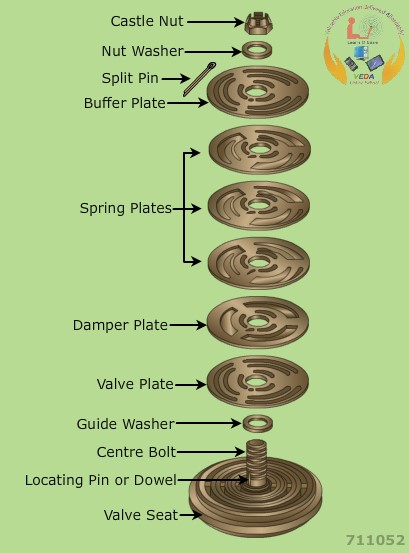
1. Valve Wire-Drawing & Throttling Pressure Drop
Air does not flow through valve openings without resistance. In a compressor running at 600 RPM, the suction valve must open, pass the full intake charge, and close in approximately 0.025 seconds!
- Friction and throttling across narrow valve slots and tortuous gas passages cause a pressure drop of 0.1 to 0.25 bar across the suction valve.
- Consequently, the pressure inside the cylinder during the intake stroke is not 1.0 bara, but only 0.85 to 0.90 bara.
- Because the density of air is directly proportional to absolute pressure, a 10% pressure drop means 10% fewer air molecules enter the cylinder per stroke, directly reducing mass delivery.
2. Valve Plate Inertia & Valve Slip
Valves are operated automatically by differential pressure against return spring tension:
- Due to mechanical inertia of the steel valve plate and damping cushion springs, the valve does not snap shut at the exact instant the piston reaches Bottom Dead Center (BDC).
- As the piston starts moving upward on its compression stroke, a fraction of the inducted air escapes (slips) backwards out through the closing suction valve into the suction manifold before the valve plate fully seats.
- If valve springs are fatigued, broken, or valve plates are coated with sticky carbon sludge, closing is delayed further, causing massive valve slip and high suction pipe pulsation.
3. Thermal Pre-Heating of the Suction Air Charge
Air enters the compressor at ambient engine room temperature (e.g. 30°C to 35°C). However, the internal surfaces of the cylinder head, liner walls, and piston crown operate at 100°C to 140°C:
- As cold air rushes across these hot metallic surfaces during the suction stroke, it rapidly absorbs heat.
- According to Charles's Law, heating a gas causes it to expand, reducing its density (ρ = P / RT).
- Although the cylinder fills its physical geometric space, the actual mass of air trapped inside is significantly reduced. When this heated air is subsequently discharged and cooled in the air receiver, its volume contracts, resulting in lost delivered capacity.
4. Piston Ring & Liner Blow-By Leakage
Compression rings must maintain a gas-tight seal against the honed cylinder liner bore:
- As running hours accumulate, abrasive airborne dust and degraded oil varnish cause liner barrel wear, ovality, and excessive ring end-gap clearances.
- During the high-pressure compression and delivery stroke, air leaks (blows by) past the ring gaps into the crankcase (or into the lower stepped cylinder chamber).
- Blow-by represents air that was drawn in, consumed compression work, but never reached the air receiver!
5. Diagnostic Protocol & Troubleshooting Matrix for Low Capacity
The primary symptom of collapsed volumetric efficiency in engine room operations is loss of pumping capacity: The main air compressor runs continuously, running hot, taking 45 to 60 minutes to charge the 30-bar starting air receivers instead of its normal 18 to 20 minutes.
A. The Marine Engineer's 5-Step Diagnostic Protocol
- Perform a Pumping Rate Test: Isolate the air bottle. Open the bottle drain to vent all water. Record the time in seconds required to pump the air bottle from 15 bar to 30 bar. Compare against sea trial baseline data.
- Inspect the Air Intake Filter: Check the suction air filter element. A choked, oil-saturated felt or paper filter starves the LP cylinder, creating a deep intake vacuum and destroying volumetric efficiency.
-
Analyze Interstage Pressure & Temperatures: Feel or measure valve pocket temperatures using an infrared thermometer:
- A hot suction valve pocket indicates valve leakage (compressed air wire-drawing back through the valve).
- Compare interstage pressure against design values (abnormal rise = HP valve failure; drop = LP valve failure).
- Bench Test Valve Tightness: Remove valve assemblies. Clean parts in solvent. Place the assembled valve on a test stand. Pour light oil or kerosene onto the valve plate: if oil weeps through within 2 to 3 minutes, the valve plate and seat must be lapped on a cast iron surface plate using fine diamond paste.
- Gauge Liner Wear & Bumping Clearance: If valves and filters are pristine, open the cylinder head. Measure bumping clearance with lead wire. Inspect liner bore with an internal cylinder dial gauge for excessive wear or ovality.
B. Master Troubleshooting Matrix: Capacity Loss & Volumetric Efficiency
| Observed Symptom | Probable Root Cause | Corrective Marine Engineering Action |
|---|---|---|
| Long bottle charging time with hot LP suction manifold | LP suction valve plate cracked, spring broken, or unseated by carbon deposits. Air leaks back out into intake manifold during compression. | Overhaul LP suction valve. Lap valve plate and seat on surface plate. Renew cracked plates and fatigued springs. Never reverse worn valve plates. |
| Long bottle charging time with LP safety valve blowing | HP suction valve leaking or broken. HP cylinder fails to inhale air; air backs up into intercooler. | Stop compressor immediately. Remove HP suction valve, lap sealing faces, replace broken springs, and clean carbonized deposits. |
| Normal interstage pressure but very slow delivery; excessive crankcase breathing | Worn piston rings, stuck rings in carbonized grooves, or scuffed cylinder liner allowing severe blow-by into crankcase. | Pull pistons. Gauge ring groove axial clearances and ring end gaps. Hone liner glaze or renew worn liner and piston rings. |
| Low delivery capacity after recent cylinder head or bearing overhaul | Excessive bumping clearance due to fitting an over-thick head gasket or fitting excessive shims at connecting rod palm. | Carry out lead wire bumping clearance measurement. Adjust shims at cylinder base or connecting rod foot to restore maker's specified clearance (0.5%–1.0% bore). |
| Air compressor runs hot; rapid loss of delivery in tropical waters | Cooling water jackets or intercooler fouled with marine growth and scale, causing excessive thermal pre-heating of suction charge. | Clean and descale cooling water jackets and intercooler tubes using inhibited sulfamic acid. Regulate cooling water flow to maintain proper discharge temperature. |
6. Power and valve condition
Valve losses affect both capacity and power.
A restricted valve may cause:
- Lower cylinder filling or delivery
- Greater pressure difference across the valve
- Higher indicated work
- Higher cylinder temperature
- Higher motor load per delivered unit
If a valve leaks, gas may be recompressed or returned to the wrong side.
A valve fault can therefore produce low capacity and high specific power simultaneously.
7. Measurement errors
False performance conclusions may come from:
- Gauge-pressure use in ratio calculations
- Incorrect temperature location
- Flow meter at a different pressure basis
- Uncalibrated pressure gauge
- Wet gas at the flow meter
- Unmeasured condensate
- Unstable receiver pressure
- Motor current used instead of real power
- Ignored auxiliary power
- Incorrect standard-condition conversion
Verify the measurement chain before opening the compressor.
8. Pressure fault diagnosis
Low discharge pressure
Possible causes:
- Low speed
- Suction restriction
- Valve leakage
- Piston-ring leakage
- Capacity-control unloading
- Air leaks
- Excessive system demand
- Incorrect pressure switch
High discharge pressure
Possible causes:
- Closed downstream valve
- Blocked pipe
- Receiver pressure high
- Faulty pressure control
- Excessive system resistance
- Wrong pressure switch setting
Abnormal interstage pressure
Possible causes:
- Stage valve fault
- Intercooler restriction
- Condensate accumulation
- Piston-ring leakage
- Incorrect load sharing
9. Diagnostic Guide: Piston, Ring & Scraper Defects
| Symptom Observed | Underlying Defect | Diagnostic Verification & Corrective Action |
|---|---|---|
| High Interstage Pressure (Rise above 5.5 bar) | HP compression ring blow-by or HP suction valve leakage. | HP annular chamber is failing to hold pressure, leaking high pressure backward into interstage pipework. Overhaul HP rings and valves. |
| Low Interstage Pressure (Drop below 4.0 bar) | LP crown compression ring blow-by or LP suction valve leaking. | LP stage cannot deliver sufficient mass flow to satisfy HP suction demand. Check LP ring end gaps and clean LP valves. |
| Excessive Sump Oil Consumption | Worn or stuck oil scraper rings on trunk skirt; choked drain holes. | Splash oil is escaping past the scraper rings and burning in cylinders. Pull piston, clean oil drain holes, fit new scraper rings. |
| Rapid Carbon Build-Up on Discharge Valves | Oil carryover past scrapers combined with high discharge temperature. | Oil is cracking on hot valve plates. Inspect cooling water flow, check bumping clearance, and renew scraper rings. |
| Knocking Noise at TDC / BDC | Incorrect bumping clearance or worn gudgeon pin / big-end bush. | Perform lead wire check immediately. Verify connecting rod palm shims and cylinder head gasket thickness against maker's manual. |
10. Component-to-symptom diagnosis
| Observation | Components to inspect first | Reason |
|---|---|---|
| Low capacity | Suction valve, discharge valve, piston rings, inlet filter, unloaders | Gas is not entering, being retained, or being delivered correctly |
| High discharge temperature | Discharge valve, cooling jacket, intercooler, rings, excessive pressure ratio | Heat is generated or not removed |
| High power | Discharge restriction, leaking valves, high pressure, bearing friction, poor intercooling | More compression or mechanical work is required |
| Oil in delivered air | Packing, scraper, distance piece, cylinder lubrication | Oil is crossing from the frame or being over-supplied |
| Packing leakage | Rod finish, rod runout, packing rings, cooling, alignment | The moving seal is overloaded or worn |
| Frame knock | Main bearing, crankpin bearing, crosshead, loose bolt, oil starvation | Running-gear clearance or support is abnormal |
| Cylinder knock | Valve, piston-to-head clearance, broken ring, liquid entry | Impact or abnormal valve movement is occurring |
| Excessive vibration | Foundation, balance, piping, pulsation, alignment, bearings | Dynamic forces are not being controlled |
| Low oil pressure | Pump, strainer, relief valve, filter, bearing clearance, oil level | Supply or internal leakage problem |
| High interstage pressure | High-pressure suction restriction, low-pressure discharge valve, cooler blockage | Gas cannot pass normally between stages |
The table is a starting point, not permission to replace parts without measurements. Confirm the symptom with pressure, temperature, vibration, oil, and capacity data.
11. Failure modes and causes
| Failure | Common mechanical causes |
|---|---|
| Crankshaft fatigue crack | Excessive bending, poor fillet condition, misalignment, overload, torsional vibration |
| Main-bearing wipe | Low oil pressure, dirty oil, excess clearance, overload, shaft misalignment |
| Crankpin bearing damage | Incorrect clearance, oil starvation, rod load, bolt or cap movement |
| Crosshead shoe wear | Poor lubrication, excessive clearance, guide distortion, dirt, side load |
| Piston-rod breakage | Excessive rod load, fatigue, bending, thread damage, incorrect pre-stress |
| Packing failure | Rod runout, poor finish, misalignment, overheating, incorrect adjustment |
| Piston or cylinder scoring | Insufficient clearance, broken ring, liquid entry, dirt, misalignment |
| Foundation cracking or movement | Excessive dynamic load, inadequate mass, poor soil, poor grout, resonance |
| Persistent frame vibration | Unbalance, couple, loose fasteners, piping forces, pulsation, resonance |
The correct repair addresses the load path. Replacing a bearing without correcting oil supply or alignment allows the failure to return.
12. Diagnostic Guide: Lubrication & Carryover Faults
| Symptom Observed | Root Cause | Corrective Action |
|---|---|---|
| Rapid crankcase oil level drop | Worn or broken piston scraper rings; choked skirt drain holes; cylinder liner ovality. | Pull pistons, measure ring end gaps and skirt clearances, clean drainage holes, renew scraper rings. |
| Heavy milky emulsion at cooler drains | High ambient engine room humidity condensing in coolers (normal), or cooler tube leak (abnormal). | Test drain fluid for salinity or coolant chemical traces; verify tube tightness via hydrostatic test. |
| Discharge valves coated in hard black carbon | Oil carryover combined with high stage temperature; incorrect oil grade (mineral engine oil used). | Clean valves with soft brass scraper, renew with synthetic ISO VG 68/100 compressor oil, check cooling water flow. |
| Low lubricating oil pressure alarm | Choked suction strainer, worn gear pump gears, excessive crankshaft bearing clearance. | Clean pump suction strainer, measure pump discharge relief pressure, inspect main and big-end bearings. |
| No discharge from auto-drain during running | Solenoid valve coil burnt out, timer failure, choked drain orifice or needle seat. | Open manual bypass drain to verify liquid accumulation; dismantle and overhaul solenoid drain valve. |
Found a mistake, or something unclear?
Report it in a few seconds — it goes straight to the editors.
- Air Compressor Principle, Thermodynamics & Multistage Advantages
- Air Compressor Types & Classification
- Air Compressor Construction — Pistons, Rings, Valves & Running Gear
- Air Compressor Working — Cycle, Volumetric Efficiency, Coolers & Capacity
- Air Compressor Operations — Lubrication, Drains & Running
- Air Compressor Maintenance — Lapping, Clearances & Overhaul
- Air Compressor Safety — Relief Devices, Receivers & SOLAS
- Air Compressor Troubleshooting — Interstage Pressure & Fault Finding