

Air Compressor Types & Classification
Positive-displacement vs dynamic families, reciprocating single/double-acting, single/multistage, air/water-cooled, trunk vs crosshead, tandem/stepped
1. The two main compressor families
Industrial compressors are first divided into:
- Positive-displacement compressors
- Dynamic compressors
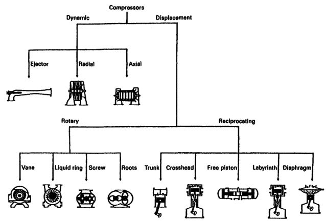
This is the first selection decision because the two families respond differently to flow, pressure, speed, system resistance, and load variation.
2. Positive-displacement compressors
A positive-displacement compressor traps successive quantities of gas in a closed or partially closed working space and raises pressure by reducing the available volume or by compressing gas within that space.
Examples:
- Reciprocating piston
- Rotary screw
- Sliding vane
- Rotary lobe
- Scroll
- Liquid piston
- Rolling piston
The basic sequence is:
Trap gas, confine gas, compress or carry the gas, discharge gas. The gas is trapped and then physically squeezed, so the pressure rise comes from a volume change.
The compressor reference describes positive-displacement machines as units in which successive gas volumes are confined and elevated to a higher pressure.
3. Dynamic compressors
A dynamic compressor continuously accelerates gas with a high-speed rotating element and converts velocity into pressure through diffusers, stationary blades, or flow passages.
Examples:
- Centrifugal or radial compressor
- Axial compressor
- Mixed-flow compressor
The basic sequence is:
Enter gas, accelerate gas, diffuse the velocity, raise the static pressure. Nothing is trapped: the pressure rise comes from changing the velocity of a continuous flow.
The gas is not trapped in isolated piston pockets. Flow is continuous through the machine.
4. Other compression methods
The compressor reference describes four broad methods:
- Trap gas, reduce its volume, and discharge it.
- Trap gas, carry it to a discharge opening, compress it by backflow from the discharge system, and discharge it.
- Accelerate gas with rotating impellers or bladed rotors and convert velocity into pressure.
- Use a high-velocity jet to entrain gas and convert mixed-flow velocity into pressure in a diffuser.
The first two are positive-displacement methods. The third is dynamic compression. The fourth is ejector or jet compression.
5. Reciprocating piston compressors
A reciprocating compressor uses:
- Cylinder
- Piston
- Piston rod
- Suction valve
- Discharge valve
- Crankshaft
- Connecting rod
- Crosshead where fitted
Gas is drawn into the cylinder, compressed by piston movement, and discharged through automatic valves.
Characteristics:
- High pressure capability
- Good efficiency over a broad pressure range
- Strong part-load control
- Pulsating flow
- Reciprocating inertia forces
- More valves and wearing parts
- Larger foundation requirement than many rotary machines
The reciprocating machine is classified as a constant-volume, variable-pressure machine: displacement is set mainly by geometry and speed, while system pressure determines the pressure rise.
6. Rotary positive-displacement compressors
Rotary positive-displacement compressors trap and move gas using rotating elements.
They normally provide:
- Continuous or near-continuous flow
- Higher speed than reciprocating machines
- Lower pulsation than piston machines
- Compact packaging
- Fewer reciprocating inertia forces
They may be sensitive to:
- Internal clearances
- Oil condition
- Rotor timing
- Gas cleanliness
- Sealing
- Built-in pressure ratio
7. Rotary screw compressors
A screw compressor uses intermeshing helical rotors to trap and reduce gas volume as it moves along the rotor flutes.
Types include:
- Oil-injected twin screw
- Oil-free twin screw
- Single-screw design
Advantages:
- Continuous flow
- Low pulsation
- Compact package
- Good automatic capacity control
- Suitable for plant air and many process services
Limitations:
- Rotor and casing clearances are critical.
- Oil-injected types require separation and oil management.
- Oil-free types require precise rotor and sealing design.
- Built-in volume ratio must match operating pressure reasonably well.
The refrigeration reference notes that screw compressors have no conventional piston clearance volume and that their internal volume ratio is set by rotor geometry.
8. Sliding-vane compressors
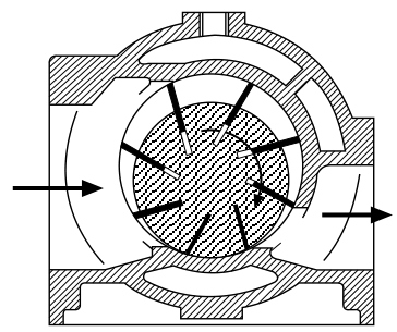
A sliding-vane compressor has a rotor mounted eccentrically in a casing. Radial vanes slide in rotor slots and form changing-volume pockets.
As the rotor turns:
- Pocket volume increases at suction.
- Gas enters the pocket.
- Pocket volume decreases.
- Gas is compressed.
- Gas leaves through the discharge port.
Advantages:
- Compact
- Smooth flow
- Simple rotary motion
- Suitable for moderate pressure and capacity
Limitations:
- Vane-tip wear
- Lubrication dependence
- Friction
- Sensitivity to liquid carryover
- Pressure limitation from vane loading
9. Rotary-lobe or Roots blowers
A lobe blower traps gas between rotating lobes and casing, then carries it from suction to discharge.
In a basic straight-lobe blower, there is little or no internal compression. Pressure rises mainly when the trapped gas meets the discharge-system pressure.
Characteristics:
- High flow
- Low-to-moderate pressure rise
- Simple rotors
- Pulsation requiring attention
- Useful for aeration, scavenging, and low-pressure air service
The compressor reference distinguishes straight-lobe machines from helical-lobe compressors and notes that straight-lobe gas is carried without internal compression.
10. Centrifugal compressors
A centrifugal compressor uses one or more rotating impellers.
Gas typically:
- Enters near the impeller eye.
- Accelerates radially outward.
- Gains velocity and kinetic energy.
- Passes through a diffuser or return passage.
- Converts velocity into static pressure.
Characteristics:
- Large continuous flow
- High rotational speed
- Low pulsation
- Compact flow path for large capacity
- Several stages may be used for higher pressure
- Performance strongly depends on flow and speed
The compressor reference defines centrifugal compressors as dynamic machines with radial gas flow through rotating impellers.
11. Axial compressors
An axial compressor uses alternating rows of rotating and stationary blades.
Gas flows mainly parallel to the shaft axis.
Each stage gives a relatively small pressure increase, so many stages are used for high overall pressure ratio.
Advantages:
- Very high flow capacity
- Compact frontal area for large flow
- Suitable for gas turbines and large air systems
Limitations:
- Narrow stable operating range
- Sensitive to fouling
- Sensitive to blade damage
- Stall and surge risk
- More difficult part-load operation
- High-speed rotating assembly
The compressor reference defines axial compressors by axial gas acceleration from bladed rotors.
12. Positive displacement versus dynamic operation
| Feature | Positive displacement | Dynamic |
|---|---|---|
| Gas handling | Trapped volumes or pockets | Continuous flow |
| Pressure generation | Volume reduction or internal compression | Velocity converted to pressure |
| Flow response | Relatively strong pressure capability | Strongly dependent on flow and speed |
| Pulsation | Reciprocating types high; rotary types lower | Usually low |
| Capacity control | Speed, unloaders, clearance, bypass | Inlet guide vanes, throttling, speed, recycle |
| Pressure ratio | High for reciprocating; moderate for rotary | Several stages often needed |
| Part-load behaviour | Often good for reciprocating | May be limited by surge or stall |
| Flow range | Small to large | Medium to very large |
| Maintenance | Valves, rings, seals, rotors | Bearings, seals, blades, fouling |
| Foundation | Reciprocating needs dynamic support | Often mainly deadweight and alignment |
13. Constant-volume and variable-pressure behaviour
A positive-displacement compressor has a nearly fixed geometric displacement per revolution.
If discharge resistance increases:
- Pressure rises.
- Driver power rises.
- Capacity may fall due to clearance and leakage.
- Relief or control action may be required.
A dynamic compressor does not force a fixed volume into the discharge system in the same way. Its pressure and flow are determined by the compressor characteristic and system resistance.
14. Flow range
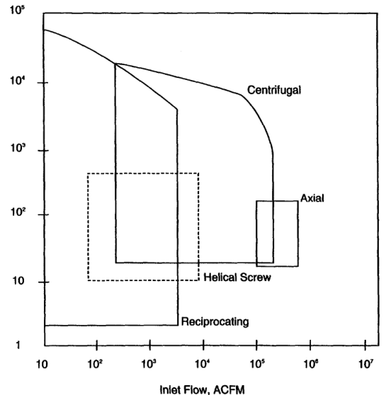
Flow rate is one of the most important selection variables.
Approximate tendencies:
- Reciprocating: low-to-high flow, especially strong at high pressure
- Rotary screw: medium flow, continuous plant air
- Rotary vane: low-to-medium flow, moderate pressure
- Roots blower: high flow, low pressure rise
- Centrifugal: high-to-very-high flow
- Axial: very-high flow
The indexed compressor reference provides approximate application ranges and notes that maximum values do not apply simultaneously to every service.
15. Pressure capability
Pressure capability depends on:
- Number of stages
- Pressure ratio per stage
- Cooling
- Material strength
- Sealing
- Valve or rotor design
- Gas temperature
- Lubrication
- Rod and frame load
Reciprocating compressors are often preferred for high pressure and lower flow.
Centrifugal compressors may be preferred for large flow and moderate pressure ratio, with multiple stages for higher pressure.
Axial compressors use many stages for large flow and moderate pressure rise per stage.
16. Speed comparison
Typical relative tendencies:
| Machine | Speed tendency |
|---|---|
| Heavy-duty reciprocating | Low to moderate |
| Small reciprocating | Moderate to high |
| Rotary screw | High |
| Rotary vane | Moderate to high |
| Centrifugal | Very high |
| Axial | Very high |
High speed reduces machine size but increases sensitivity to:
- Rotor balance
- Bearing condition
- Seal performance
- Blade condition
- Dynamic instability
- Lubrication
17. Pulsation comparison
Reciprocating compressors create discrete suction and discharge events, producing pulsation.
Rotary positive-displacement machines provide more continuous flow but may still produce rotor-passing pulsation.
Centrifugal and axial machines generally produce smoother flow, although aerodynamic disturbances and rotating stall can produce severe pressure fluctuations.
Pulsation matters because it affects:
- Piping vibration
- Valve life
- Foundation loading
- Flow-meter accuracy
- Noise
- Card interpretation
- System reliability
18. Surge and stall in dynamic compressors
Dynamic compressors require a stable relationship between flow and pressure rise.
Surge
A system-level instability in which flow oscillates or reverses because the compressor is operating below its stable flow range.
Stall
Local flow separation or blade aerodynamic failure that reduces pressure generation.
Possible results:
- Severe vibration
- Reversed flow
- High bearing loads
- Blade damage
- Driver instability
- Rapid temperature changes
Positive-displacement compressors do not experience aerodynamic surge in the same way, although they have their own pressure, pulsation, unloading, and valve-instability problems.
19. Slip and leakage in positive-displacement machines
Positive-displacement machines depend on sealing between working pockets and casing or rotor surfaces.
Leakage or slip increases when:
- Clearances grow
- Rotors wear
- Seals fail
- Gas viscosity changes
- Pressure ratio increases
- Temperature changes
Effects:
- Lower capacity
- Higher power per delivered unit
- Higher temperature
- Reduced pressure capability
Reciprocating machines use piston rings and valves; rotary machines depend on rotor clearances, seals, oil, or liquid sealing.
20. Reciprocating advantages
A reciprocating compressor is often attractive when:
- Pressure is high.
- Flow is moderate.
- Load varies widely.
- High efficiency is required.
- Several pressure stages are needed.
- Gas composition varies.
- Capacity control must be precise.
- Part-load efficiency matters.
- A positive-displacement characteristic is useful.
It can be configured as:
- Single- or double-acting
- Single- or multistage
- Air- or water-cooled
- Lubricated or non-lubricated
- Horizontal, vertical, V, Y, or opposed
- Single- or multicylinder
21. Reciprocating limitations
Limitations include:
- Pulsating flow
- Foundation and vibration requirements
- More valves and wearing parts
- Larger package for high flow
- Liquid intolerance
- Lubricant carryover risk
- More complicated maintenance
- Rod-load and frame-load limits
Clean, dry intake gas is important. Liquid carryover can damage valves and remove lubrication.
22. Rotary-screw advantages
Screw compressors are attractive when:
- Continuous flow is required.
- Flow is medium to high.
- Pressure is moderate.
- Low pulsation is desirable.
- Compact packaging matters.
- Automatic part-load control is required.
They are common for:
- Plant air
- Instrument air
- Workshop air
- Refrigeration
- Process gas
Oil-injected and oil-free designs have different air-quality and maintenance requirements.
23. Centrifugal advantages
Centrifugal compressors are attractive when:
- Flow is high.
- Flow is continuous.
- Pressure ratio per casing is moderate.
- Low pulsation is important.
- A turbine or high-speed driver is available.
- Foundation movement must be low.
The selection reference notes that centrifugal compressors deserve early consideration when the driver must be a turbine, while reciprocating compressors are often favourable with electric motors.
This is a selection tendency, not an absolute rule.
24. Axial advantages
Axial compressors are attractive when:
- Very high flow is required.
- Compact flow area is important.
- Several stages can be accommodated.
- The service resembles gas-turbine or large process-air duty.
They are less common for ordinary marine starting-air and instrument-air packages because those services usually favour reciprocating or rotary machines.
25. Driver compatibility
Driver selection affects compressor selection.
Consider:
- Electric motor speed
- Steam turbine speed
- Gas-engine speed
- Variable-speed drive capability
- Starting torque
- Power availability
- Exhaust or waste-heat integration
- Hazardous-area requirements
- Emergency operation
A compressor must match the driver’s speed, power, torque, control, and starting characteristics.
26. Foundation and vibration
Reciprocating machines generate inertia forces from:
- Piston acceleration
- Connecting rods
- Crankshaft rotation
- Gas pulsation
They may require:
- Rigid foundation
- Correct mass and stiffness
- Anchor bolts
- Pulsation bottles
- Flexible pipe connections
- Alignment control
Centrifugal machines generally have lower reciprocating inertia forces, but rotor balance and foundation stiffness remain essential.
The reference notes that centrifugal machines operate without reciprocating unbalanced forces, while reciprocating units require mounting that stabilises the installation.
27. Cooling requirements
Cooling selection depends on:
- Pressure ratio
- Gas flow
- Discharge temperature limit
- Ambient temperature
- Cooling-water availability
- Fouling environment
- Installation location
Reciprocating high-pressure machines commonly use cylinder jackets, intercoolers, and aftercoolers.
Rotary screw machines may use oil cooling and oil separators.
Centrifugal and axial machines use aerodynamic and bearing/seal cooling arrangements.
28. Lubrication and gas quality
Lubrication may be:
- Frame-only
- Cylinder lubricated
- Oil-injected
- Oil-free
- Liquid-sealed
Selection depends on whether oil contamination is acceptable.
Oil-free or labyrinth-piston machines may be selected for:
- Oxygen service
- Instrument air
- Chemical gas
- Food or pharmaceutical service
- Processes sensitive to oil contamination
Non-lubricated designs require careful attention to wear materials, clearances, heat, and sealing.
29. Marine-service examples
Starting air
Typical priorities:
- High pressure
- Reliable storage charging
- Good condensate separation
- High safety integrity
- Automatic start/stop
- Redundant or standby capacity
Reciprocating multistage compressors are common.
Instrument air
Typical priorities:
- Low oil carryover
- Dry air
- Reliable pressure
- Filtration and drying
- Stable automatic control
Oil-free reciprocating or oil-free screw designs may be selected.
Service or workshop air
Typical priorities:
- Moderate pressure
- Variable demand
- Low lifecycle cost
- Easy maintenance
- Good part-load control
Rotary screw or reciprocating machines may be suitable.
Large continuous process air
Typical priorities:
- Very high flow
- Continuous operation
- Low pulsation
- Turbine or high-speed driver compatibility
Centrifugal or axial machines may be appropriate.
30. Selection inputs
The compressor selection reference lists the following essential inputs:
- Required discharge pressure.
- Required capacity.
- Power supply characteristics.
- Cooling-water availability and cost.
- Space.
- Weight.
- Foundation type and size.
- Control type.
- Maintenance cost.
Also specify:
- Suction pressure range
- Suction temperature range
- Gas composition
- Humidity or liquid content
- Duty cycle
- Required availability
- Air-quality requirement
- Noise limit
- Hazardous-area classification
- Future capacity increase
31. Selection decision sequence
- Define the gas and inlet condition.
- Define the required mass flow and pressure.
- Check the pressure ratio and temperature.
- Choose positive displacement or dynamic.
- Compare candidate types.
- Check the driver and speed.
- Check cooling, space, foundation and controls.
- Check lifecycle cost and maintenance.
- Confirm safety and air quality.
Each step narrows the field; skipping one is how the wrong machine gets ordered.
Do not start by choosing a familiar machine. Start with the duty.
32. Preliminary selection matrix
| Requirement | Likely family |
|---|---|
| Very high pressure, moderate flow | Reciprocating |
| Moderate pressure, continuous plant air | Rotary screw |
| Low-pressure, high-flow air | Lobe blower or centrifugal |
| Very high continuous flow | Centrifugal or axial |
| Wide part-load range | Reciprocating or well-controlled screw |
| Low pulsation | Screw or dynamic |
| Oil-free high-pressure gas | Oil-free reciprocating or specialised screw |
| Turbine driver | Centrifugal often considered early |
| Electric motor, high pressure | Reciprocating often considered early |
| Low vacuum or jet service | Ejector or specialised compressor |
This matrix is preliminary. Final selection requires manufacturer data.
33. Capacity-control comparison
Reciprocating
- Suction-valve unloaders
- Clearance pockets
- Start-stop
- Bypass
- Variable speed
- Cylinder cutout
Screw
- Slide valve
- Variable-speed drive
- Inlet modulation
- Stop-start
Centrifugal
- Inlet guide vanes
- Inlet throttling
- Speed control
- Recycle or blow-off
Axial
- Variable inlet guide vanes
- Variable stator vanes
- Speed control
- Bleed or bypass systems
The control method strongly affects part-load power and operating range.
34. Maintenance comparison
| Machine | Main maintenance focus |
|---|---|
| Reciprocating | Valves, rings, packing, lubrication, alignment |
| Screw | Oil, separator, rotor clearances, bearings, seals |
| Vane | Vanes, casing, lubrication, wear |
| Lobe | Timing gears, clearances, bearings, pulsation |
| Centrifugal | Bearings, seals, impellers, diffusers, fouling |
| Axial | Blades, bearings, clearances, fouling, stall/surge protection |
A machine with lower first cost may have higher maintenance or energy cost.
35. Gas characteristics and selection
Gas properties influence selection:
- Molecular weight
- Specific heat ratio
- Compressibility
- Toxicity
- Flammability
- Corrosiveness
- Dew point
- Liquid content
- Lubricant compatibility
Low-density gas affects centrifugal compressors strongly because the machine may need more stages or a larger size to achieve the required pressure.
Positive-displacement machines may tolerate low-density gas differently, but capacity and sealing still change.
36. Liquid handling
Compressors generally prefer gas without entrained liquid.
Liquid can:
- Damage reciprocating valves
- Wash lubrication from cylinders
- Damage rotary clearances
- Cause screw separator problems
- Damage centrifugal blades
- Cause surge-like disturbances
Install and maintain:
- Suction separators
- Demisters
- Drains
- Interstage separators
- Aftercoolers
- Automatic or manual condensate systems
37. Selection example
Duty
A ship requires:
- Moderate flow
- High stored-air pressure
- Intermittent charging
- Reliable automatic operation
- Limited cooling-water availability
- High pressure and safety priority
Preliminary choice
A multistage reciprocating compressor is a strong candidate because it provides:
- High pressure capability
- Good intermittent-duty performance
- Effective capacity control
- Manageable flow at high pressure
- Intercooling and condensate removal
A rotary screw may be considered if continuous flow, lower pulsation, and moderate pressure are more important.
A centrifugal machine is less likely to be economical for this moderate-flow, high-pressure intermittent duty.
38. Why classification matters
“Reciprocating compressor” identifies only the broad machine family.
A complete description must also identify:
- Acting arrangement
- Number of stages
- Cooling method
- Cylinder lubrication
- Frame arrangement
- Cylinder arrangement
- Duty rating
- Portability
- Driver
- Service gas
Example:
Water-cooled, lubricated-frame, non-lubricated-cylinder, two-stage, double-acting, V-type, stationary reciprocating air compressor.
This description immediately communicates more useful information than “air compressor.”
39. Single-acting compressor
A single-acting compressor compresses gas on one side of the piston only.
The arrangement runs from the cylinder head, through the suction and compression space and the piston, to the crankcase. Only the space between the head and the piston does work, so the machine compresses once per revolution.
The crank end is not used as a compression chamber.
Characteristics:
- One working end
- Simpler cylinder arrangement
- Lower capacity for a given bore and speed
- Fewer valves
- Easier construction
- Common in small and moderate-duty machines
The basic single-cylinder reciprocating element is single-acting.
40. Double-acting compressor
A double-acting compressor compresses gas on both sides of the piston.
A head-end chamber and a crank-end chamber lie either side of the piston, and both compress. Each chamber compresses on one stroke, so the machine works twice per revolution.
Each end has suction and discharge valves.
Characteristics:
- Higher capacity for a given bore and speed
- Better use of both sides of the stroke
- More valves and passages
- Piston rod packing required
- More complex lubrication and sealing
- Common in heavy-duty continuous-service machines
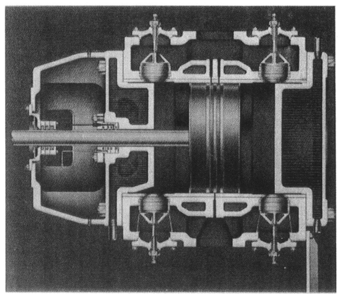
The reference defines double-acting compressors as machines with intake and discharge valves at both cylinder ends.
41. Single-acting versus double-acting
| Feature | Single-acting | Double-acting |
|---|---|---|
| Compression sides | One | Two |
| Capacity per bore | Lower | Higher |
| Valves | One working end | Both ends |
| Rod packing | Usually not in gas cylinder | Required at crank end |
| Construction | Simpler | More complex |
| Foundation/load | Lower for comparable small duty | Higher possible output |
| Typical use | Small/moderate duty | Heavy-duty continuous service |
| Maintenance | Fewer cylinder components | More valves and packing |
Double-acting does not automatically mean more efficient in every service; it means both piston sides perform compression work.
42. Single-stage compressor
A single-stage compressor completes the pressure rise from suction to final discharge in one compression step.
Advantages:
- Simple piping
- Fewer valves
- No interstage cooler
- Lower initial cost
- Simple maintenance
Limitations:
- Higher discharge temperature
- Higher pressure ratio per cylinder
- Lower volumetric efficiency at high ratio
- Greater rod and frame loading
- More difficult high-pressure operation
43. Multistage compressor
A multistage compressor divides the total pressure rise into two or more stages.
Typical arrangement:
LP stage, intercooler, HP stage, aftercooler. Each stage takes part of the rise, with cooling in between to bring the air back down.
Advantages:
- Lower ratio per stage
- Lower peak temperature
- Lower power with effective intercooling
- Better high-pressure operation
- Reduced pressure differential per cylinder
- Condensate removal between stages
Limitations:
- More valves and coolers
- More piping and separators
- Pressure-drop losses
- More maintenance
- Higher initial cost
The compressor reference defines single-stage, multistage, and two-stage machines by the number of distinct compression steps.
44. Air-cooled compressor
An air-cooled compressor rejects heat through fins, surrounding air, or a fan-assisted air path.
Advantages:
- No cooling-water system
- Simple installation
- Useful where water is unavailable
- Lower risk of water-side corrosion
- Suitable for intermittent or moderate duty
Limitations:
- Depends on ambient air temperature
- Lower heat-transfer capacity
- Higher cylinder temperature at high load
- Noise from fan and airflow
- Finned surfaces can foul
- Less suitable for sustained high-pressure duty
Air-cooled cylinders commonly use cast or machined cooling fins.
45. Water-cooled compressor
A water-cooled compressor uses jackets around cylinders and heads, plus water-cooled intercoolers and aftercoolers where required.
Advantages:
- Better heat removal
- Lower gas temperature
- Improved lubrication
- Lower valve deposits
- Higher continuous-duty capability
- Better high-pressure suitability
- Lower power in some services
Limitations:
- Cooling-water pumps and piping
- Fouling and scale
- Corrosion
- Water-leak risk
- Freeze or low-temperature condensation risk
- Need for flow monitoring
The reference states that water-cooled cylinders can operate at higher compression ratios because they do not depend mainly on radiation for heat rejection.
46. Air-cooled versus water-cooled
| Feature | Air-cooled | Water-cooled |
|---|---|---|
| Cooling medium | Ambient air | Fresh, treated, or circulating water |
| Installation | Simpler | More equipment |
| Continuous duty | More limited | Better suited |
| Temperature control | Ambient-dependent | More controllable |
| Fouling | Fins and air passages | Jackets, tubes, strainers |
| Corrosion risk | Lower water risk | Water-side corrosion possible |
| High-pressure service | Limited by temperature | More suitable |
| Maintenance | Fan/fins | Pump, jacket, cooler, drains |
47. Moderate-duty compressor
Moderate-duty machines are generally intended for intermittent or limited continuous operation.
Typical characteristics:
- Often single-acting
- Often air-cooled
- Lower horsepower
- Lower speed or lighter construction depending on design
- Smaller foundation
- Simpler controls
- Lower initial cost
The reference describes moderate-duty units as commonly single-acting and often air-cooled, with water-cooled options in some horsepower ranges.
A moderate-duty rating does not mean unsafe or poor quality. It means the thermal, structural, and maintenance assumptions differ from continuous heavy-duty design.
48. Heavy-duty or continuous-duty compressor
A heavy-duty continuous-service reciprocating compressor is generally associated with:
- Water-cooled cylinders
- Double-acting compression
- Separate crosshead
- Pressure lubrication
- Strong frame
- Low-to-moderate rotational speed
- Intercooling and aftercooling
- Designed foundation
- Continuous monitoring
The reference notes that heavy-duty continuous-duty reciprocating compressors are generally both water-cooled and double-acting.
49. Lubricated cylinder
A lubricated cylinder uses controlled oil injection or distribution to lubricate:
- Piston rings
- Cylinder wall
- Valve components where permitted
- Packing or other moving sealing surfaces
Advantages:
- Lower friction
- Reduced wear
- Better sealing
- Longer ring life
- Tolerance of some operating conditions
Limitations:
- Oil carryover
- Oil separation and filtration
- Deposit formation
- Gas contamination
- Oil compatibility requirements
The lubricant must match gas composition, temperature, pressure, and material compatibility.
50. Non-lubricated or oil-free cylinder
A non-lubricated cylinder is designed so the compression chamber does not receive conventional cylinder oil.
This may use:
- Carbon or filled-polymer rings
- Special rider bands
- Labyrinth piston
- Dry-running sealing materials
- Carefully controlled clearances
- Separate frame lubrication
Advantages:
- Low oil contamination
- Suitable for sensitive process gas
- Useful for oxygen, instrument air, and clean gas
Limitations:
- Greater sensitivity to dirt and moisture
- Special wearing materials
- Higher maintenance precision
- Possible lower allowable temperature or speed
- More demanding installation cleanliness
Non-lubricated does not mean the entire machine contains no oil. The frame, bearings, and crank mechanism may still use oil.
51. Lubrication classification
Use precise language:
- Oil-lubricated cylinder: oil enters the gas cylinder.
- Non-lubricated cylinder: cylinder is designed without conventional oil injection.
- Oil-free gas: delivered gas meets a specified contamination limit; it does not necessarily mean the machine has no oil anywhere.
- Oil-free frame: crankcase or frame lubrication differs from cylinder lubrication.
The reference warns that “non-lubricated” descriptions can be misleading unless cylinder and frame systems are distinguished.
52. Trunk-piston design
A trunk piston is guided directly by its skirt within the cylinder.
Characteristics:
- Piston skirt provides guidance
- Compact construction
- Suitable for higher speed than many crosshead designs
- Common in moderate-duty machines
- Crankcase and cylinder may be closer together
- Oil control depends on rings and design
Trunk-piston compressors resemble the guidance arrangement of an engine.
53. Crosshead design
A crosshead separates piston guidance from the cylinder wall.
Motion path:
Crankshaft, connecting rod, crosshead, piston rod, piston. The crosshead takes the side load, so the piston rod and bore see no lateral force.
Advantages:
- Piston is guided by crosshead shoes.
- Piston can be narrower.
- More valve area may be available.
- Longer stroke is possible.
- Crankcase oil is separated from cylinder gas.
- Piston slap and ring wear can be reduced.
- Higher-pressure construction is possible.
The reference lists these as major crosshead benefits in heavy-duty compressors.
54. Trunk piston versus crosshead
| Feature | Trunk piston | Crosshead |
|---|---|---|
| Piston guidance | Piston skirt | Crosshead and guide |
| Package | Compact | Larger and heavier |
| Speed | Often higher | Usually lower/moderate |
| Oil separation | More difficult | Better separation |
| Stroke | More limited by design | Longer stroke practical |
| Gas cleanliness | More oil-control challenge | Better control |
| Service | Moderate duty | Heavy-duty/high-pressure |
| Maintenance | Piston and skirt | Crosshead, shoes, rod, packing |
55. Horizontal arrangement
In a horizontal compressor, cylinders lie horizontally from the frame.
Advantages:
- Accessible cylinder heads and valves
- Convenient for large cylinders
- Common in heavy-duty process machines
- Can be arranged opposed for force balance
Limitations:
- Long foundation
- Alignment sensitivity
- Horizontal piston weight and rider-band loading
- Large maintenance envelope
56. Vertical arrangement
In a vertical compressor, cylinders stand above the frame.
Advantages:
- Smaller floor footprint
- Compact arrangement
- Good drainage in some layouts
- Common in moderate-duty and selected heavy-duty machines
Limitations:
- Greater height
- Overhead maintenance access
- Vertical piping and lifting requirements
- Dynamic forces transmitted through the frame and foundation
The reference includes vertical and horizontal single-cylinder arrangements when discussing inertia forces.
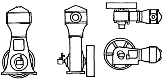
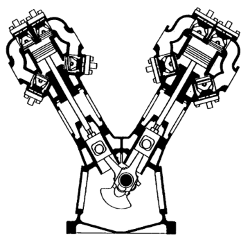
57. V-type arrangement
A V-type compressor has cylinders arranged at an angle, commonly around 45° from vertical, and driven from a common crank arrangement.
Advantages:
- Compact footprint
- Several cylinders in a short frame
- Useful force arrangement
- Common for two-cylinder compressors
Limitations:
- More complex access
- Cylinder-angle piping
- Shared-crank loading
- Foundation forces require analysis
58. Y-type arrangement
A Y-type machine uses three cylinder directions or a geometry resembling a Y.
It can provide:
- Multiple cylinders on a compact frame
- Improved force distribution
- Capacity expansion without a long inline frame
The exact balance depends on crank angles, cylinder masses, and phase relationships.
Do not assume every Y-frame is dynamically balanced; inspect the manufacturer’s force and couple analysis.
59. Single-frame straight-line arrangement
A straight-line machine places one or more cylinders in line on one frame.
It may be:
- Horizontal
- Vertical
- Single- or double-acting
- Motor-driven
- Steam-driven
- Tandem with driver cylinders
The reference identifies single-frame straight-line machines as horizontal or vertical double-acting compressors with cylinders in line on a frame.
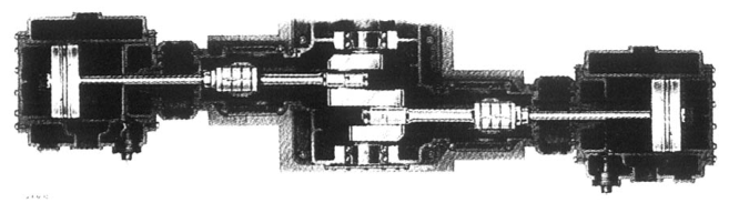
60. Opposed arrangement
An opposed compressor places cylinders on opposite sides of the crankcase.
Advantages:
- Good primary-force cancellation
- Compact moment arms
- Reduced foundation loading
- Suitable for large process machines
- High capacity in a balanced structure
Limitations:
- Multiple crank throws
- More complex frame and alignment
- Opposed cylinder access
- Crosshead and rod inspection requirements
Balanced-opposed arrangements can transfer couples even when direct forces cancel.
61. Semi-radial arrangement
A semi-radial compressor combines features of V/Y layouts with additional cylinders on each side.
It can provide:
- High capacity
- Compact footprint
- Shared crankshaft
- Multiple cylinders with selected phasing
The cylinder and crank arrangement must be checked for:
- Primary forces
- Secondary forces
- Couples
- Piping arrangement
- Maintenance access
62. Duplex arrangement
A duplex compressor has cylinders on two parallel frames connected through a common crankshaft or drive arrangement.
Possible purposes:
- Greater capacity
- Redundancy within a common package
- Multiple services
- Shared driver or crankshaft
- Flexible loading
A duplex machine is not automatically two independent standby compressors; the common frame, shaft, or driver may remain a single point of failure.
63. Tandem arrangement
Tandem cylinders or pistons are arranged along one line or rod.
Applications include:
- Multiple stages on one axis
- Compact driver-cylinder arrangements
- Selected pressure-ratio designs
Tandem piston rods carry combined loads, so frame and rod-load limits must be checked.
The reference describes tandem piston rods with two or more pistons mounted on one rod where combined loading remains within allowable limits.
64. Four-cornered arrangement
A four-cornered motor-driven compressor uses multiple compressing cylinders around a central or shared drive arrangement.
A steam-driven four-cornered machine may place driver and compressor cylinders at opposite ends of frames.
Advantages:
- Compact use of a common driver
- Multiple services or stages
- Potential force balancing
Limitations:
- Complex crankshaft and frame
- Difficult alignment
- More extensive piping and maintenance planning
65. L-type or integral arrangement
An L-type integral machine may combine:
- Vertical or vertical-V power cylinders
- Horizontal compressor cylinders
- Common crankshaft or integral driver
This arrangement is often associated with gas- or oil-engine-driven compressors.
Selection depends on:
- Available fuel
- Driver speed
- Foundation
- Maintenance access
- Heat balance
- Service pressure and capacity
66. Portable compressor
A portable compressor and driver are mounted so the unit can be moved as a package.
Typical requirements:
- Skid or frame
- Lifting points
- Vibration isolation
- Flexible hoses
- Compact receiver or no receiver
- Quick connection
- Protection from transport damage
Portable units may sacrifice some cooling, noise, maintenance access, or continuous-duty capability for mobility.
67. Stationary compressor
A stationary compressor is permanently installed on a foundation or equipment skid.
Advantages:
- Larger capacity
- Better cooling systems
- Permanent piping
- Larger receiver and separators
- More robust controls
- Easier integration with plant systems
Installation must include:
- Foundation
- Alignment
- Piping flexibility
- Pulsation control
- Drainage
- Ventilation
- Maintenance access
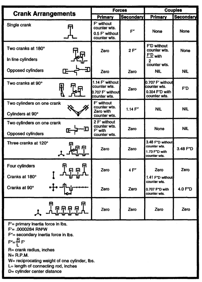
68. Cylinder arrangement and force balance
Reciprocating masses create:
- Primary inertia forces
- Secondary inertia forces
- Primary couples
- Secondary couples
- Gas forces
The arrangement determines how these forces combine.
A good arrangement may:
- Cancel opposing forces
- Reduce couples
- Lower foundation vibration
- Reduce piping movement
- Improve bearing load distribution
The arrangement must be considered with actual crank angles and cylinder masses, not only with its visual shape.
69. Cylinder arrangement and capacity
Capacity can be increased by:
- Increasing bore
- Increasing stroke
- Increasing speed
- Adding cylinders
- Using double-acting cylinders
- Adding stages
- Using multiple frames
Each option changes:
- Driver power
- Rod load
- Foundation force
- Pulsation
- Cooling requirement
- Maintenance
Adding cylinders is not only a capacity decision; it is a dynamic and structural decision.
70. Cylinder arrangement and maintenance
Inline
- Simple sequence
- Easy to understand
- Long frame and piping
- Access may be good from one side
V/Y
- Compact footprint
- More complex valve and piping access
- Shared-crank maintenance
Opposed
- Good balance
- Multiple cylinder ends on both sides
- Large maintenance envelope
Duplex
- Multiple services or capacity
- More complex shaft and frame
71. Lubricated versus non-lubricated selection
Choose non-lubricated or oil-free cylinder construction when:
- Product gas must not contain oil.
- Oxygen or reactive gas is handled.
- Instrument air quality is critical.
- Downstream oil removal is difficult.
- Process contamination is costly.
Choose lubricated construction when:
- Oil carryover is acceptable or removable.
- High sealing and wear resistance are needed.
- Simpler cylinder maintenance is preferred.
- Gas and lubricant are compatible.
Non-lubricated machines require exceptionally clean intake and interstage piping; dirt, rust, scale, and moisture accelerate wear.
72. Air-cooled versus water-cooled selection
Choose air cooling when:
- Duty is intermittent.
- Capacity is small or moderate.
- Cooling water is unavailable.
- Simplicity and mobility matter.
- Ambient temperature is acceptable.
Choose water cooling when:
- Duty is continuous.
- Pressure ratio is high.
- Discharge temperature must be controlled.
- Cooling water is available.
- Long valve and lubricant life matter.
Cooling-water failure should produce an alarm or trip where temperature risk is significant.
73. Moderate-duty versus heavy-duty selection
| Requirement | Moderate duty | Heavy duty |
|---|---|---|
| Operating pattern | Intermittent or limited continuous | Continuous |
| Cooling | Often air | Usually water |
| Acting | Often single | Commonly double |
| Guidance | Trunk piston | Crosshead |
| Speed | Often higher | Often lower |
| Foundation | Smaller | Designed heavy foundation |
| Maintenance | Simpler | More detailed |
| Cost | Lower initial | Higher initial, lifecycle focus |
The correct rating depends on actual load factor, not only the motor horsepower.
74. Marine-service classification example: starting-air compressor
A typical starting-air compressor may be described as:
Stationary, water-cooled, multistage, double-acting or heavy-duty reciprocating compressor with automatic capacity control, intercooling, aftercooling, moisture separation, and receiver charging.
Important checks:
- Final pressure
- Charging time
- Standby availability
- Condensate drainage
- Relief valves
- Cooling-water flow
- Oil carryover
- Receiver safety
75. Marine-service classification example: instrument air
A typical instrument-air compressor may be described as:
Stationary, oil-free-cylinder, water- or air-cooled compressor with filtration, drying, receiver storage, automatic control, and low oil carryover.
Important checks:
- Dew point
- Oil contamination
- Part-load operation
- Dryer capacity
- Receiver pressure
- Redundancy
- Valve and ring materials
76. Marine-service classification example: workshop air
A workshop compressor may be:
Portable or stationary, air-cooled or water-cooled, single- or two-stage, single-acting reciprocating or rotary screw compressor with receiver and automatic pressure control.
Selection depends on:
- Intermittent demand
- Portability
- Noise
- Pressure
- Flow
- Available power
- Maintenance resources
77. Why classification affects spare parts
Classification determines likely spare parts:
Single-acting air-cooled
- Piston rings
- Suction and discharge valves
- Fan components
- Filters
- Gaskets
Double-acting water-cooled crosshead
- Valve assemblies
- Piston rings
- Rider bands
- Packing rings
- Crosshead shoes
- Bearings
- Cooler seals
- Jacket components
Non-lubricated
- Special dry-running rings
- Rider bands
- Clean-service filters
- Special valve materials
Correct classification improves spare-parts planning.
78. Classification and operating procedures
The classification determines operating precautions.
Air-cooled
- Keep fins clean.
- Maintain fan airflow.
- Avoid prolonged overload.
- Observe ambient temperature.
Water-cooled
- Confirm water flow before starting.
- Monitor inlet and outlet temperature.
- Prevent fouling and scale.
- Avoid condensation from overcooling.
Non-lubricated
- Maintain clean intake gas.
- Prevent moisture and rust scale.
- Use correct dry-running materials.
Double-acting
- Monitor both cylinder ends.
- Inspect packing.
- Compare valve temperatures.
79. Selection is an engineering decision
A compressor is normally expected to operate for many years. Its purchase price is only one part of the ownership cost. Electricity or fuel consumed over the operating life can be many times the initial equipment cost, especially on heavy-duty service. A compressor that is cheap to buy but inefficient, poorly controlled, difficult to cool, or expensive to maintain can be the most expensive choice in service.
The selection sequence should therefore be:
- define the gas and duty;
- establish the required flow and pressure envelope;
- identify acceptable compressor families;
- compare staging, cooling, lubrication, control, and driver options;
- check mechanical, foundation, space, and maintenance constraints;
- compare life-cycle cost and availability; and
- obtain a guaranteed performance proposal from suitable manufacturers.
The first choice is commonly between positive-displacement and dynamic compression. A reciprocating compressor is a positive-displacement machine: each cylinder traps a volume and reduces it mechanically. A centrifugal or axial compressor is dynamic: it adds velocity to the gas and converts velocity into pressure. The pressure, capacity, gas properties, and operating range determine which family is appropriate.
Design rule: never select a compressor from discharge pressure alone. Pressure, flow, suction conditions, gas composition, operating hours, control range, and site conditions must be considered together.
80. Required duty data
A manufacturer cannot rate a compressor reliably from a statement such as “air compressor, 100 bar.” The following information is required.
2.1 Gas identity and composition
State whether the gas is atmospheric air, nitrogen, oxygen, hydrogen, natural gas, refrigerant, process gas, or a mixture. For a process gas, provide the composition over its expected operating range.
Important properties include:
- molecular weight or specific gravity;
- compressibility factor;
- ratio of specific heats, k;
- moisture content and dew point;
- corrosive, toxic, flammable, or polymerising constituents;
- entrained liquid or solid particles;
- allowable oil carryover; and
- chemical compatibility with seals, piston rings, valves, and lubricants.
Gas composition can change the suitability and cost of compressor types. Low-density gas generally affects centrifugal machines more severely because the machine may require more stages or a larger size to produce the required pressure rise. A positive-displacement compressor is less sensitive to specific gravity in its basic displacement, although power, rod load, temperature, valve performance, and volumetric efficiency still change.
2.2 Suction condition
Record:
- suction pressure, absolute and gauge where relevant;
- suction temperature;
- altitude or site elevation;
- inlet pressure loss;
- maximum, normal, and minimum suction pressure; and
- whether the suction gas is saturated, superheated, wet, or contaminated.
Compressor capacity is based on the mass entering the machine, while many air ratings are stated as free-air delivery or actual inlet volume. These must not be mixed. A quoted “100 cfm” is incomplete unless its reference pressure, temperature, humidity, and location are stated.
At altitude, atmospheric pressure and absolute inlet pressure decrease. The compressor must handle a larger inlet volume for the same mass flow, and its performance must be derated or the low-pressure cylinder enlarged. A machine suitable at sea level may not deliver the same mass flow at an elevated installation.
2.3 Discharge condition
State:
- required discharge pressure;
- normal and maximum discharge pressure;
- required discharge temperature or maximum permissible temperature;
- pressure losses in aftercoolers, separators, dryers, filters, valves, and piping;
- receiver pressure range; and
- whether the pressure is measured at the compressor flange or at the point of use.
The compressor must produce enough pressure to overcome downstream losses while remaining below the maximum allowable pressure of the weakest component. Do not size the compressor only for the nominal receiver pressure if the system has substantial pressure drop.
2.4 Capacity and demand profile
Give capacity as a mass flow or as a clearly defined standard/free-air volume. State:
- minimum, normal, and maximum demand;
- start-up and peak demand;
- expected future expansion;
- number of operating hours per day and per year;
- whether demand is steady, cyclic, or intermittent;
- required turndown; and
- consequences of loss of pressure.
A ship’s starting-air compressor may run intermittently but must recharge receivers within a specified time. Instrument air may have a smaller flow but stricter cleanliness and dew-point requirements. Workshop air may have a highly variable demand. These services should not be treated as one generic “compressed-air load.”
81. Preliminary compressor-family selection
3.1 Reciprocating compressors
Reciprocating compressors are positive-displacement machines suited to:
- relatively low to very high discharge pressures;
- low to moderate flow per machine;
- high pressure ratio per stage or per machine;
- variable demand with stepped or automatic capacity control;
- process duties requiring several separate streams; and
- applications where a motor-driven machine is convenient.
They provide nearly constant-volume delivery with variable pressure. They are often efficient over a broad range of pressure duties, but have pulsating flow, reciprocating inertia forces, valves, rings, packing, and a greater maintenance burden than a simple dynamic machine.
3.2 Rotary positive-displacement compressors
Rotary vane, screw, lobe, and related machines provide smoother flow than a reciprocating compressor. They are often attractive for moderate pressure and continuous flow. Their suitability depends strongly on oil-free requirements, internal clearances, seal arrangements, speed, and the gas being handled.
A small centrifugal or rotary machine is not automatically preferable to a reciprocating machine. An oil-free or partially lubricated reciprocating design may be better for a small, clean-gas duty where the alternative has an unsuitable sealing system.
3.3 Centrifugal compressors
Centrifugal compressors are dynamic machines commonly selected for large continuous flows. They have no reciprocating inertia forces and can have a relatively simple foundation requirement, but their performance is sensitive to suction conditions, gas density, operating point, and surge margin.
If suction pressure rises, the discharge pressure and horsepower may exceed the design point. If suction pressure falls, the machine may fail to reach the required discharge pressure. Suction and discharge pressure variation must therefore be evaluated rather than using only nominal values.
3.4 Axial-flow compressors
Axial compressors are used for very large flows and comparatively modest pressure rise per stage, such as gas-turbine and process applications. They require careful control of operating range and are generally not the first choice for a small marine service-air or starting-air installation.
3.5 Approximate application ranges
The source text gives broad, non-guaranteed maximum values: reciprocating compressors up to approximately 20,000 bhp and 100,000 psig in special applications; centrifugal machines up to approximately 60,000 bhp and 10,000 psig; and axial-flow machines up to approximately 100,000 bhp and 500 psig. These are not selection limits. They are reminders that the ranges overlap and that other constraints can govern.
82. Pressure ratio and staging
The overall pressure ratio is
rp = pd/ps
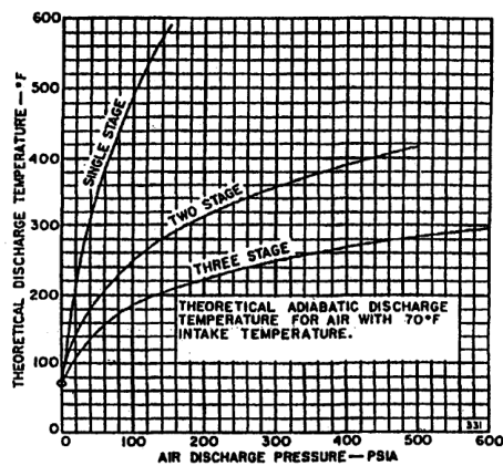
where pressures are absolute. A high pressure ratio in one cylinder causes high discharge temperature, reduced volumetric efficiency, greater valve stress, and increased lubrication and deposit problems.
4.1 Single-stage selection
Single-stage compression is suitable when the pressure ratio and discharge temperature remain within the machine’s permissible limits. It is attractive because it has fewer cylinders, valves, coolers, drains, and controls.
For industrial air service, the source notes that single-stage units are generally used to about 50 psig in moderate-duty service, while water-cooled units can reach higher single-stage pressures under appropriate conditions. Exact limits depend on cylinder size, speed, cooling, gas, valve design, and manufacturer rating.
4.2 Multistage selection
Multistage compression divides the total pressure ratio into two or more stages. With effective intercooling, the gas approaches its original suction temperature before entering the next stage. This reduces compression work and discharge temperature.
For an ideal two-stage arrangement with equal stage pressure ratios:
rstage ≈ √(rp)
For N equal stages:
rstage ≈ rp^1/N
The real optimum must include pressure drops through valves, piping, intercoolers, separators, and coolers. Adding stages indefinitely is not beneficial: after several stages, friction and equipment losses may offset the theoretical saving.
A two-stage compressor delivering air at 100 psig can save approximately 10–15% power compared with single-stage compression under the conditions described in the source. Heavy-duty water-cooled compressors are often two-stage for 100 psig air service above approximately 125 bhp.
4.3 Intercoolers and aftercoolers
An intercooler removes heat between stages. It reduces the inlet temperature of the next stage and lowers the work required. A separator should remove condensed moisture or liquid after cooling so that liquid does not enter the next cylinder.
An aftercooler reduces final discharge temperature after the last stage. Cooling air below approximately 100°F, where practical, allows a substantial amount of moisture to condense before the air reaches the receiver. A moisture separator and reliable drain are then essential.
The selection must include:
- cooler approach temperature;
- cooling-water temperature and fouling allowance;
- pressure drop;
- condensate removal;
- material compatibility; and
- access for cleaning.
4.4 Stage pressure balance
If stage ratios are badly unbalanced, one stage may operate at excessive temperature or power while another is underloaded. Interstage pressure restrictions must be included in the calculation. A blocked cooler, fouled separator, or undersized interstage pipe changes the actual stage pressure and can overload a cylinder.
83. Capacity, load factor, and control
5.1 Rated capacity is not average demand
A compressor selected exactly at the maximum instantaneous demand may spend much of its life lightly loaded, while a compressor selected at the average demand may be unable to maintain pressure during peaks. The installation should be evaluated using a demand profile.
Load factor is the ratio of actual compressed-gas output while operating to rated full-load output during that same period. The source recommends avoiding a continuous 100% load factor and gives a general design range of approximately 50–80%, depending on machine size, type, and number of units.
Benefits of sensible load factor include:
- more uniform pressure during peaks;
- cooling-off periods, especially for air-cooled units;
- reserve capacity for leakage, expansion, and fouling; and
- lower risk of continuous operation at the limiting temperature or rod load.
5.2 Capacity-control methods
Reciprocating compressors can control capacity using:
- start–stop control;
- speed control where the driver permits it;
- suction-valve unloaders;
- suction-valve lifters;
- clearance pockets;
- bypass or free-flow unloading;
- reverse-flow unloading; and
- combinations of these methods.
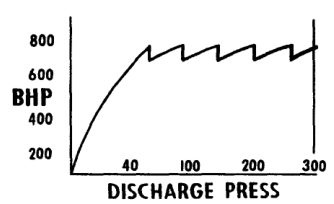
The control system must sense pressure, relay the demand signal, and actuate the unloading mechanism. Capacity control may be required to limit flow, prevent excessive horsepower, maintain discharge pressure, or protect the driver.
A fixed-speed compressor commonly operates at 0%, 50%, 75%, or 100% capacity through stepped unloading. More steps give closer matching to demand and can reduce wasted power, but add valves, controls, instrumentation, and maintenance points.
5.3 Multiple compressors
Several smaller compressors can provide:
- standby capacity;
- staged operation as demand changes;
- easier maintenance without total loss of service;
- lower minimum turndown; and
- improved response to intermittent ship or plant loads.
A single large machine may have lower installed cost and better efficiency at full load. The correct arrangement depends on reliability requirements, available space, spare philosophy, starting current, maintenance resources, and the demand profile.
Process plants may use one driver to handle multiple streams. Reciprocating machines provide considerable flexibility in the number and size of services connected to a common driver, but the capacity and pressure-control interactions must be analysed.
84. Driver selection
The compressor and driver are one system. Consider:
- electric motor, steam turbine, gas engine, or gas turbine availability;
- starting torque and acceleration time;
- supply voltage, frequency, and short-circuit capacity;
- variable-speed or fixed-speed operation;
- hazardous-area classification;
- waste-heat or exhaust-gas opportunities;
- coupling, gearbox, and alignment requirements;
- overspeed protection;
- emergency or blackout operation; and
- maintenance skill and spare parts.
If the power source dictates the driver, the compressor should be selected to fit that driver. The source notes that a centrifugal machine often receives first consideration when a turbine is required, while a reciprocating compressor often receives first consideration for a motor-driven application. This is a preliminary tendency, not an absolute rule.
The driver must be checked at:
- normal suction and discharge conditions;
- maximum pressure;
- start-up and pull-down conditions;
- unloading and reloading;
- low-voltage or low-steam conditions; and
- fouled cooler or high ambient conditions.
Do not rate the motor only against normal running power. A pressure rise, cooler fouling, or control failure can increase the required power.
85. Cooling selection
7.1 Air cooling
Air cooling avoids cooling-water pumps, strainers, treatment, drains, and freezing risk. It may be appropriate for small or intermittent moderate-duty machines where ambient air is clean and the heat can be rejected safely.
Limitations include:
- dependence on ambient temperature;
- fan power and noise;
- dirty fins and restricted airflow;
- high discharge temperature at high ambient; and
- reduced cooling-off opportunity if the compressor is continuously loaded.
7.2 Water cooling
Water-cooled jackets remove heat from the cylinder and reduce gas temperature. Lower temperature improves lubrication, reduces deposits on valves, extends valve life, reduces cylinder maintenance, and can reduce power. Water cooling also allows higher single-stage pressure under suitable conditions.
The selection must include:
- available flow and pressure;
- inlet temperature and seasonal variation;
- water quality and scaling tendency;
- corrosion control;
- strainers and cleaning access;
- cooling-water failure protection; and
- treatment or chemical cleaning provisions.
A water-cooled heavy-duty unit normally runs at lower speed and temperature than an air-cooled unit of comparable service, so maintenance can be lower. However, a neglected water jacket can foul and create the same overheating problem the cooling system was installed to prevent.
7.3 Cooling-system failure consequences
High discharge temperature can cause:
- less effective lubrication;
- deposits on valves;
- shorter valve life;
- higher cylinder maintenance cost; and
- increased fire risk in discharge piping where oil and deposits are present.
Temperature alarms, high-temperature shutdowns, cooling-water flow indication, and reliable drains should be treated as part of the compressor selection—not as optional accessories added later.
86. Lubrication and gas cleanliness
The required gas cleanliness can determine the cylinder construction. Lubricated cylinders are generally simpler and can have good wear resistance, but oil carryover may be unacceptable for oxygen, breathing air, instrumentation, food, chemical, or catalyst service.
For oil-free service consider:
- non-lubricated piston rings and rider bands;
- separate lubricated frame and crankcase where permitted;
- piston-rod packing and distance pieces;
- labyrinth piston construction;
- oil-removal filters and separators;
- compatibility of materials with the gas; and
- the actual cleanliness guarantee, not merely the label “oil-free.”
Oil-free does not mean maintenance-free. Non-lubricated rings, rider bands, packing, and valves remain wear components. Gas inlet filtration is critical because solids can damage rings and valves, while liquids can cause impact damage, corrosion, and loss of lubrication.
87. Space, weight, foundation, and vibration
9.1 Floor space
Provide the manufacturer with the actual available length, width, and height, not only an approximate room area. Include:
- valve and cylinder removal paths;
- overhead lifting clearance;
- cooler and separator access;
- motor or coupling removal space;
- pipe flexibility;
- control-panel access; and
- safe operator walkways.
A compressor that physically fits but cannot be overhauled in place is not a suitable selection.
9.2 Weight and foundation
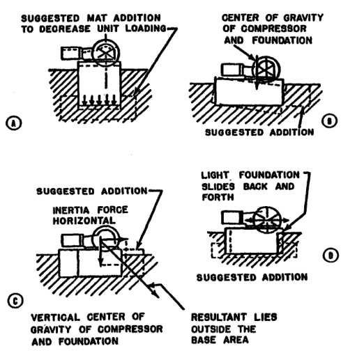
Reciprocating compressors generate inertia forces and couples. The foundation must support dead weight, resist sliding and rocking, maintain alignment, and distribute load safely to the soil. The compressor base, foundation, and connected piping must be considered together.
A centrifugal compressor has no reciprocating unbalanced forces and may require a simpler foundation, although stiffness and alignment remain important. A reciprocating machine may require a heavier foundation, vibration analysis, anchor bolts, and flexible piping supports.
Foundation checks include:
- safe dynamic soil-bearing capacity;
- uniform load distribution;
- centre of gravity and resultant load position;
- resistance to sliding;
- sufficient mass and stiffness;
- temperature effects; and
- avoidance of piping forces being transmitted into the cylinder.
9.3 Pulsation and piping
Pulsating flow is inherent in reciprocating compressors. Piping natural frequencies, pulsation bottles, supports, valves, and branch connections must be analysed. Poor piping can cause vibration, fatigue, valve problems, and inaccurate capacity measurements even when the compressor itself is correctly rated.
88. Marine application examples
10.1 Starting air
Starting-air service requires adequate receiver recharge, high reliability, appropriate discharge pressure, aftercooling, moisture separation, and safe relief protection. The demand is intermittent but the consequence of failure is high. A duty/standby arrangement is often more valuable than one oversized compressor.
Selection questions:
- How many consecutive engine starts must the receiver support?
- What is the required recharge time?
- Is the compressor arranged for automatic start?
- Is condensate removed from the aftercooler and receiver?
- Is oil carryover controlled to reduce deposit and fire risk?
- Can one unit maintain the vessel during maintenance on the other?
10.2 Instrument air
Instrument air requires reliable pressure, low moisture, and low contamination. The compressor package should be evaluated with dryers, filters, drains, receiver volume, and standby philosophy. A compressor with adequate flow but poor moisture control is not adequate instrument-air equipment.
10.3 Workshop and service air
Workshop demand is variable and often includes intermittent high-flow tools. A receiver and stepped capacity control can prevent frequent starts and reduce pressure fluctuation. The compressor should not be sized solely from the sum of tool nameplates; diversity and simultaneous-use factors are needed.
10.4 Emergency and blackout requirements
Where compressed air supports emergency machinery, the selection must include the available emergency power source and restart sequence. A compressor that cannot start against receiver pressure or cannot unload during starting may fail precisely when it is needed.
89. Life-cycle cost
A proper comparison includes:
- compressor and driver purchase price;
- coolers, separators, filters, dryers, receivers, and controls;
- foundations and installation;
- electrical switchgear or steam-system modifications;
- energy cost;
- cooling-water and treatment cost;
- lubricant and filter cost;
- planned maintenance;
- valves, rings, packing, and other spares;
- downtime and lost production;
- training and specialist service; and
- disposal or replacement cost.
Power cost deserves special attention. Even a small efficiency difference becomes significant when the machine operates thousands of hours per year. Compare power at the actual duty profile, not only at rated full load.
A simple annual energy estimate is:
Eannual = Pinput × toperating
where Pinput is the real input power and toperating is the annual operating time. For variable demand, calculate several load points and apply their operating hours rather than multiplying full-load power by total calendar time.
90. Common selection mistakes
Mistake 1 — using gauge pressure in the pressure-ratio calculation
Pressure ratios require absolute pressure. Gauge pressure can seriously understate the ratio at low suction pressures.
Mistake 2 — confusing free-air delivery with actual inlet volume
The same mass flow occupies different volumes at different pressures and temperatures. Always state the reference condition.
Mistake 3 — sizing from average demand only
Peak demand, receiver recharge, future expansion, and acceptable pressure dip must be considered.
Mistake 4 — ignoring pressure drop between stages
Intercoolers, separators, valves, and piping alter stage pressure and can overload a stage.
Mistake 5 — selecting air cooling without checking ambient conditions
High ambient temperature, dirty fins, and continuous load can produce unacceptable discharge temperature.
Mistake 6 — treating oil-free as maintenance-free
Oil-free cylinders still require inspection and replacement of rings, rider bands, packing, and valves.
Mistake 7 — selecting the smallest possible foundation
Foundation cost is small compared with the cost of chronic vibration, alignment loss, cracked piping, and repeated shutdowns.
Mistake 8 — comparing purchase prices without energy cost
Power cost over the service life may dominate the economic comparison.
Mistake 9 — forgetting maintenance access
A package that cannot remove a valve, piston, cooler bundle, or motor safely will have excessive downtime.
Mistake 10 — accepting an unqualified performance curve
The curve must identify gas, suction state, discharge state, speed, cooling conditions, and measurement reference.
91. Worked selection approach
Case: marine service-air installation
Assume a vessel requires compressed air for workshop tools, control service, and intermittent pneumatic equipment.
Step 1 — define the pressure
Establish the receiver pressure, minimum pressure at the farthest user, filter and dryer losses, and required compressor discharge pressure. Use absolute pressure for ratio calculations.
Step 2 — define the demand
Separate continuous instrument demand from intermittent tool demand. Determine simultaneous use and identify the worst credible peak.
Step 3 — choose receiver volume
A receiver smooths demand, reduces rapid cycling, and provides short-duration reserve. It does not replace adequate compressor capacity or a recharge-time calculation.
Step 4 — compare compressor families
For moderate flow and a substantial pressure ratio, a reciprocating compressor is a strong candidate. For a large continuous flow with a narrow operating range, a rotary or centrifugal option may deserve comparison.
Step 5 — choose staging and cooling
If the pressure and temperature make single-stage compression severe, select two-stage compression with intercooling, moisture separation, and an aftercooler.
Step 6 — choose the control range
Use start–stop, load–unload, or stepped unloading according to receiver size, motor starts, demand variation, and required pressure stability.
Step 7 — choose redundancy
For safety-related or continuous service, compare one large unit against two or more units with duty/standby or duty-assist operation.
Step 8 — verify installation
Check foundation, vibration, pipe supports, lifting access, ventilation, cooling water, electrical starting current, noise, and maintenance clearances.
Step 9 — compare life-cycle cost
Include energy, cooling, filters, oil, valves, rings, planned maintenance, and the financial consequence of downtime.
Practise this in the question bank
- Air Compressor (motor) — 6 questions
Found a mistake, or something unclear?
Report it in a few seconds — it goes straight to the editors.
- Air Compressor Principle, Thermodynamics & Multistage Advantages
- Air Compressor Types & Classification
- Air Compressor Construction — Pistons, Rings, Valves & Running Gear
- Air Compressor Working — Cycle, Volumetric Efficiency, Coolers & Capacity
- Air Compressor Operations — Lubrication, Drains & Running
- Air Compressor Maintenance — Lapping, Clearances & Overhaul
- Air Compressor Safety — Relief Devices, Receivers & SOLAS
- Air Compressor Troubleshooting — Interstage Pressure & Fault Finding