

Air Compressor Working — Cycle, Volumetric Efficiency, Coolers & Capacity
Four-event reciprocating cycle and PV indicator cards, volumetric efficiency and clearance re-expansion with bumping-clearance lead-wire measurement,
1. The positive-displacement principle
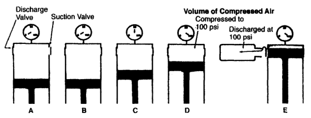
A reciprocating compressor traps a quantity of gas in a cylinder and reduces its volume with a piston.
The piston does not force gas continuously through an open passage. It repeatedly fills, closes, compresses, and discharges a separate volume of gas.
The compressor reference describes a reciprocating compressor as a piston, cylinder, and valve arrangement in which pressure rises as piston volume is reduced.
2. The four basic events
An ideal single-acting cycle contains four events:
- Suction or intake
- Compression
- Discharge
- Expansion or re-expansion of clearance gas
The order on an ideal indicator diagram is commonly represented as:
- 1 to 2: compression.
- 2 to 3: discharge.
- 3 to 4: clearance-gas expansion.
- 4 to 1: suction.
The cycle repeats every revolution for a single-acting cylinder. In a double-acting cylinder, an equivalent cycle occurs on both sides of the piston, displaced in crank angle.
3. Event 1 — Suction stroke
During suction:
- The piston moves away from the cylinder head.
- Cylinder volume increases.
- Cylinder pressure falls below suction-line pressure.
- The suction valve opens.
- Gas flows into the cylinder.
- The discharge valve remains closed.
- Near the end of the stroke, piston deceleration allows the suction valve to close.
The valve does not open simply because the piston starts moving. It opens when cylinder pressure becomes sufficiently lower than suction pressure.
Suction pressure difference
Psuction,line > Pcylinder
This pressure difference drives gas into the cylinder.
Suction valve closing
The suction valve should close close to the end of the intake stroke. If it closes too early, the cylinder is underfilled. If it closes too late, gas may flow back into the suction passage during the beginning of compression.
4. Event 2 — Compression stroke
During compression:
- The piston reverses direction.
- The suction valve closes.
- The discharge valve remains closed.
- Cylinder volume decreases.
- Gas pressure rises.
- Gas temperature rises.
- The piston continues until cylinder pressure exceeds discharge-line pressure sufficiently to open the discharge valve.
The ideal compression path is often represented by:
PV^n=C
where n depends on heat transfer and actual operating conditions.
For ideal adiabatic compression:
PV^k=C
For ideal isothermal compression:
PV=C
Actual compression usually lies between these ideal limits.
5. Event 3 — Discharge stroke
During discharge:
- Cylinder pressure rises slightly above discharge-line pressure.
- The discharge valve opens.
- The piston continues toward the cylinder head.
- Compressed gas is pushed into the discharge passage.
- Cylinder pressure approaches discharge pressure.
- Near the end of the stroke, piston speed reduces.
- The discharge valve closes as pressure equalises and flow reverses tendency.
The discharge valve requires an opening pressure above the line pressure because it must overcome:
- Spring force
- Valve-plate inertia
- Static pressure equalisation
- Flow resistance
- Pulsation effects
The compressor reference states that cylinder pressure must exceed discharge-line pressure by a small amount before the discharge valve opens.
6. Event 4 — Clearance-gas re-expansion
At the end of discharge, a small quantity of gas remains trapped in the cylinder and valve pockets.
This gas is at approximately discharge pressure.
When the piston reverses:
- The discharge valve closes.
- Trapped high-pressure gas expands.
- Cylinder pressure falls.
- The suction valve remains closed while cylinder pressure is above suction pressure.
- The suction valve opens only after cylinder pressure falls slightly below suction-line pressure.
This is the re-expansion portion of the cycle.
The re-expansion stroke does not draw fresh gas into the cylinder. It uses part of the piston travel to expand gas already inside the cylinder.
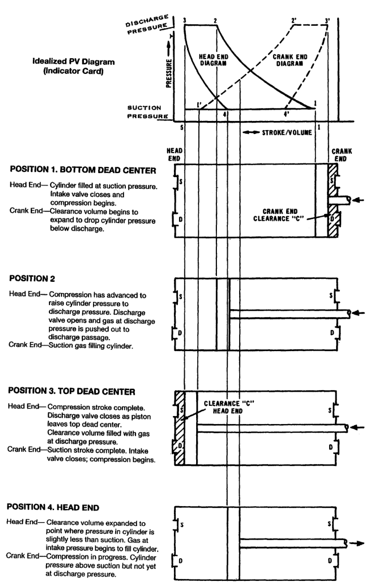
7. Position 2 — Discharge-valve opening
At position 2:
- Cylinder volume has decreased.
- Cylinder pressure has risen above discharge-line pressure.
- The discharge valve opens.
- Gas begins entering the discharge passage.
The pressure must be slightly above line pressure because a real valve has opening resistance.
The pressure difference needed to open a valve depends on:
- Spring characteristics
- Valve mass
- Valve lift
- Gas flow rate
- Pulsation
- Valve-seat condition
- Pressure equalisation
A high opening difference indicates increased valve loss or a mechanical problem.
8. Position 4 — Suction-valve opening
At position 4:
- The piston has started its return stroke.
- Clearance gas has expanded.
- Cylinder pressure has fallen below suction-line pressure.
- The suction valve opens.
- Fresh gas begins filling the cylinder.
The volume between position 4 and position 1 is the effective intake volume.
It is smaller than the full swept volume because some piston travel was consumed by clearance-gas expansion.
9. Dead-centre positions
Top dead centre
At top dead centre:
- Piston velocity is momentarily zero.
- Piston reverses direction.
- Clearance volume is minimum.
- Cylinder may contain high-pressure trapped gas.
- Valve timing changes from discharge to re-expansion.
Bottom dead centre
At bottom dead centre:
- Piston velocity is momentarily zero.
- Piston reverses from suction to compression.
- The suction valve should close.
- The cylinder contains its fresh charge.
Dead-centre positions are not necessarily the exact valve-opening positions because pressure equalisation, valve inertia, and flow dynamics affect timing.
10. Single-acting and double-acting operation
Single-acting compressor
Compression occurs on one side of the piston only.
The head end performs compression and suction; the crank end is a crankcase or low-pressure space.
Double-acting compressor
Compression occurs on both sides of the piston.
The head end runs one cycle and the crank end runs an equivalent cycle, phase-shifted by half a revolution.
The two sides have separate suction and discharge valves. The piston rod passes through a packing arrangement at the crank end.
In a double-acting cylinder, one side may be compressing while the other side is filling. This provides more capacity for a given frame and speed but adds packing, valve, and rod-load considerations.
The compressor reference distinguishes single-acting operation, where compression occurs on one side, from double-acting operation, where it occurs on both sides.
11. Cycle timing in a double-acting cylinder
A double-acting cylinder has two overlapping cycles:
| Head end | Crank end |
|---|---|
| Compression | Suction |
| Discharge | Compression |
| Re-expansion | Discharge |
| Suction | Re-expansion |
The crank-end cycle is approximately 180° out of phase with the head-end cycle, subject to actual valve timing and geometry.
This arrangement smooths the delivery compared with a single-acting cylinder but does not eliminate pulsation.
12. Piston displacement
Piston displacement is the geometric volume swept by the piston per unit time at rated speed.
For a single-acting cylinder:
PD = A × L × N
For a double-acting cylinder, both head-end and crank-end swept volumes are included, with the crank-end volume reduced by piston-rod area.
A simplified double-acting relationship is:
PD ≈ (Ahead+Acrank)LN
where:
- A = effective piston area
- L = stroke length
- N = cycles per unit time
The exact unit conversion depends on whether dimensions are in metres, millimetres, inches, cubic metres per minute, or cubic feet per minute.
The appendix gives piston-displacement relationships for single- and double-acting cylinders.
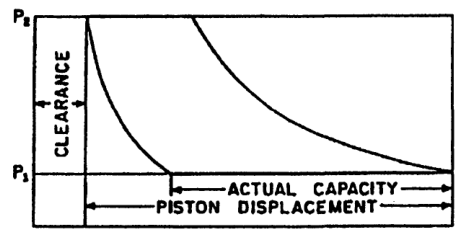
13. Piston displacement versus actual capacity
Piston displacement is not the same as actual delivered air.
Actual capacity is reduced by:
- Clearance volume
- Valve pressure losses
- Leakage past piston rings
- Leakage through valves
- Heating of suction gas
- Flow restrictions
- Unloading devices
- Pulsation
Therefore:
Qactual = PD × η_v
where:
- Qactual = actual inlet-volume capacity
- PD = piston displacement
- η_v = volumetric efficiency
A compressor can have a large geometric displacement but deliver less air than expected if its cycle is inefficient.
14. Clearance volume
Clearance volume is the volume remaining between the piston and cylinder head at the end of the stroke, including valve-pocket and passage volume.
Clearance is required for:
- Mechanical safety
- Thermal expansion
- Manufacturing tolerance
- Valve installation
- Piston deflection
- Operating alignment
Clearance cannot be reduced to zero in a practical machine.
Typical normal clearance varies by design and cylinder type. The indexed reference gives a broad range of approximately 4–16% for many standard cylinders.
15. Clearance and capacity loss
At the end of discharge, clearance gas remains at high pressure.
During the return stroke, this gas must expand before the suction valve can open.
Increasing clearance causes:
- Longer re-expansion
- Later suction-valve opening
- Smaller effective intake stroke
- Lower volumetric efficiency
- Lower actual capacity
More clearance retains more trapped gas, requiring more re-expansion before fresh gas enters. This reduces fresh-gas intake and capacity.
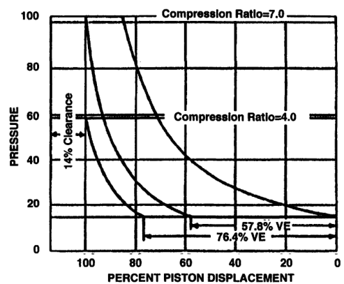
16. Clearance and compression ratio
The effect of clearance becomes worse as compression ratio increases.
Compression ratio:
r = Pdischarge,absolute/Psuction,absolute
At a higher ratio:
- Clearance gas reaches a higher pressure.
- More expansion is required before suction begins.
- Effective intake volume decreases.
- Volumetric efficiency falls.
This is why high-ratio single-stage compressors can lose capacity rapidly.
17. Clearance does not automatically increase power
For a compressor designed for a specified capacity and operating condition, normal clearance primarily reduces capacity.
If the compressor must still deliver the same mass flow, it may need:
- Higher speed
- Larger cylinder
- More cylinders
- Longer operating time
- Different operating point
Those changes may increase power in the complete system.
The normal geometric clearance itself is not automatically equivalent to a separate power load at fixed design capacity; its principal direct effect is reduced fresh-gas intake.
18. Compression ratio is a system condition
Compression ratio is not controlled only by the compressor.
It depends on:
- Suction pressure
- Discharge pressure
- Receiver pressure
- System restrictions
- Filter condition
- Cooler pressure drop
- Atmospheric pressure
For example, at sea level, 100 psig discharge is approximately:
Pd = 100 + 14.7 = 114.7 psia
With suction at 14.7 psia:
r = 114.7/14.7 ≈ 7.8
The compressor reference uses this type of calculation for air service.
19. Actual indicator card
An actual indicator card differs from the ideal card.
Typical features:
- Suction line below suction pressure
- Compression curve rounded by heat transfer
- Discharge opening above line pressure
- Discharge line above system pressure
- Pressure pulsations
- Delayed valve closure
- Uneven re-expansion
- Ring leakage
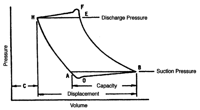
The card can be used to estimate indicated power and identify abnormal cylinder behaviour.
20. Ideal cycle versus actual cycle
| Feature | Ideal cycle | Actual cycle |
|---|---|---|
| Valve opening | Exactly at line pressure | Requires pressure difference |
| Valve closing | Instantaneous | Delayed and dynamic |
| Flow path | No restriction | Pressure losses |
| Gas leakage | None | Possible through rings and valves |
| Pressure lines | Smooth and constant | Pulsating and distorted |
| Compression | Ideal PV^n path | Heat transfer and losses |
| Clearance | Accounted for ideally | Geometric and valve-pocket volume |
| Work | Theoretical | Higher indicated work |
21. Suction-valve fault symptoms
A leaking or restricted suction valve can cause:
- Low suction filling
- Reduced capacity
- High suction-side pressure loss
- Higher cylinder temperature
- Abnormal p-V card
- Possible reverse flow during compression
- Increased power per unit of delivered gas
If a suction valve does not close properly, compressed gas can flow back toward the suction line.
If it opens late, the effective suction stroke is shortened.
If its spring is too stiff, a larger pressure difference is needed to open it.
22. Discharge-valve fault symptoms
A leaking or restricted discharge valve can cause:
- High discharge temperature
- Low delivered capacity
- High cylinder pressure late in the stroke
- Reverse flow during re-expansion
- Valve-cover heating
- Excessive pressure loss
- Abnormal p-V card
If the discharge valve opens late, the piston must compress above line pressure for longer.
If it fails to seat, high-pressure gas returns to the cylinder during the next suction or compression event.
23. Piston-ring leakage
Piston rings seal the moving piston against the cylinder wall.
Ring leakage allows gas to pass from the high-pressure side toward the low-pressure side.
Effects:
- Lower capacity
- Higher cylinder temperature
- Reduced compression efficiency
- Pressure loss during compression
- Possible contamination of crankcase in lubricated machines
- Increased oil carryover risk
Ring leakage often produces a distorted compression path rather than a clean valve-opening fault.
24. Clearance fault versus valve fault
Excessive clearance
Expected pattern:
- Longer re-expansion
- Later suction opening
- Reduced effective intake volume
- Lower volumetric efficiency
- Pressure curve may otherwise appear smooth
Suction-valve fault
Expected pattern:
- Abnormal suction pressure loss
- Delayed opening or poor closing
- Possible reverse flow
- Irregular suction line
Discharge-valve fault
Expected pattern:
- Delayed discharge opening
- High pressure before opening
- High discharge temperature
- Possible pressure pulsations
Diagnosis requires pressure, temperature, capacity, and card evidence together.
25. Suction and discharge valve design implications
Suction and discharge valves experience different conditions.
Suction valve
- Lower pressure differential during opening
- Inlet gas may be cool
- Must admit gas with low pressure drop
- Must close reliably before compression
Discharge valve
- Higher gas temperature
- Larger pressure differential
- Higher impact and flow loading
- Greater risk of deposits
- Must close before re-expansion
Valve design must account for pressure, temperature, speed, gas composition, lubrication, and pulsation.
26. Cycle interpretation: low capacity
If capacity is low, work through the cycle in order:
- Is suction pressure available?
- Is the suction filter restricted?
- Does the suction valve open fully?
- Does it close at the correct point?
- Is clearance excessive?
- Is compression pressure rising normally?
- Does the discharge valve open?
- Is discharge pressure too high?
- Are piston rings leaking?
- Is the compressor unloaded or bypassing?
Do not immediately replace a valve without checking system pressure and unloading controls.
27. Cycle interpretation: high temperature
High discharge temperature may result from:
- High compression ratio
- Restricted suction
- Restricted discharge
- Leaking discharge valve
- Poor cooling
- High intake temperature
- Ring leakage
- Excessive valve pressure loss
- Wrong gas composition
- Liquid or deposit damage
Compare the affected cylinder with the other cylinders.
A single abnormal cylinder suggests a local valve, ring, clearance, or cooling fault. All cylinders being hot suggests a system or cooling condition.
28. Cycle interpretation: knocking
Possible causes of cylinder knocking include:
- Loose piston
- Insufficient end clearance
- Excessive piston-to-bore clearance
- Broken piston ring
- Loose rider band
- Loose or broken valve
- Moisture carryover
- Liquid slugging
Liquid cannot be compressed like gas. A liquid slug can generate severe impact loads and break valve seats or other components.
The indexed maintenance reference identifies liquid carryover and insufficient clearance among causes requiring investigation.
29. Liquid carryover and the cycle
Liquid entering the cylinder disrupts the normal gas cycle.
Instead of gas being compressed smoothly:
- Liquid occupies cylinder volume.
- Piston motion creates hydraulic impact.
- Valve plates may strike or break.
- Lubrication may be washed away.
- Rings may wear rapidly.
- Pressure pulses may become severe.
Drain separators, intercoolers, and low points before liquid can reach the cylinder.
30. Basic piston-displacement calculation
Problem
A single-acting cylinder has:
- Bore diameter = 100 mm
- Stroke = 120 mm
- Speed = 600 rpm
Find approximate geometric displacement per minute.
Solution
Piston area:
A = π D²/4
A = π(0.1)²/4=0.00785 m²
Swept volume per revolution:
Vr = A L = 0.00785 × 0.12 = 0.000942 m³
At 600 rpm:
PD = 0.000942 × 600 = 0.565 m³/min
This is piston displacement, not guaranteed delivered capacity.
If volumetric efficiency is 80%:
Qactual=0.565×0.80=0.452 m³/min
31. Double-acting displacement concept
For a double-acting cylinder, both piston sides contribute.
However, the crank-end effective area is smaller because the piston rod occupies part of the cylinder area.
Approximate displacement:
PD = [Ahead+(Ahead-Arod)]LN
The exact formula depends on the manufacturer’s convention and whether the stated displacement includes both ends.
Always confirm:
- Single or double acting
- Head-end area
- Crank-end area
- Rod diameter
- Stroke
- Rated speed
- Number of cylinders
32. Compression-ratio example
A compressor receives air at 1.0 bara and discharges at 8.8 bara.
r=8.8/1.0=8.8
If suction is 1 bara and discharge is quoted as 7.8 barg:
Pd=7.8+1.0=8.8 bara
The ratio is therefore 8.8:1, not 7.8:1.
33. Why suction pressure controls capacity
If suction pressure falls:
- Gas density falls.
- Mass admitted per swept volume falls.
- Compression ratio rises.
- Volumetric efficiency may decrease.
- Capacity falls.
- Power per unit of delivered mass may increase.
Possible causes:
- Intake filter restriction
- Suction valve fault
- Low atmospheric pressure
- Suction pipe restriction
- Excessive intake temperature
34. Clearance, swept volume, and effective volume
Definitions:
- Swept volume: volume moved by the piston between dead centres.
- Clearance volume: volume remaining at the end of the compression stroke.
- Total cylinder volume: clearance volume plus swept volume.
- Effective suction volume: volume filled with fresh gas after clearance-gas re-expansion.
Total geometric volume equals clearance volume plus swept volume. Fresh-gas intake is less than swept volume because trapped clearance gas must expand before fresh air can enter.
This distinction is central to volumetric efficiency.
35. Indicator-card work areas
An actual card can be divided conceptually into:
- Useful compression work
- Suction-valve loss
- Discharge-valve loss
- Port and passage loss
- Pulsation distortion
The compressor maintenance reference explains that the enclosed p-V area represents compression work and that valve and flow-resistance areas represent additional energy expenditure.
The card is therefore both:
- A thermodynamic work measurement.
- A diagnostic picture of valve and cylinder condition.
36. Ideal cycle drawing exercise
Draw the following from memory:
- Horizontal volume axis.
- Vertical pressure axis.
- Suction pressure line.
- Discharge pressure line.
- Compression curve 1–2.
- Discharge line 2–3.
- Re-expansion curve 3–4.
- Suction line 4–1.
- Clearance volume at position 3.
- Piston positions at each point.
Then add real-machine effects:
- Suction pressure loss.
- Discharge pressure loss.
- Delayed valve opening.
- Rounded compression path.
- Pressure pulsation.
37. What an indicator card shows
An indicator card is a graph of cylinder pressure against cylinder volume or piston position during one compressor cycle.
A conventional p-V card has:
- Vertical axis: cylinder pressure
- Horizontal axis: cylinder volume
- Closed loop: one complete cycle
- Enclosed area: indicated compression work
The card shows how gas pressure changes while the piston moves and valves open or close.
The p-V diagram is both a thermodynamic measurement and a diagnostic record.
38. Ideal cycle points
The ideal cycle is commonly labelled:
- Point 1: start of compression
- Point 2: discharge valve opens
- Point 3: end of discharge and start of clearance-gas expansion
- Point 4: suction valve opens
Processes:
- 1 to 2: compression.
- 2 to 3: discharge.
- 3 to 4: clearance-gas re-expansion.
- 4 to 1: suction.
The indexed compressor reference explains each point using piston position and automatic valve action.
39. Point 2 — discharge valve opens
At point 2:
- The cylinder pressure has risen above discharge-line pressure.
- The discharge valve opens.
- Compressed gas begins to leave the cylinder.
- The p-V curve changes from compression to discharge.
In a real machine, cylinder pressure must exceed line pressure by enough to overcome:
- Valve spring force
- Valve inertia
- Static pressure equalisation
- Port resistance
- Gas acceleration
The higher the pressure difference needed to open the valve, the larger the valve-loss area on the card.
40. Point 4 — suction valve opens
At point 4:
- Clearance gas has expanded.
- Cylinder pressure has fallen slightly below suction-line pressure.
- The suction valve opens.
- Fresh gas starts entering.
The volume from point 4 to point 1 is the effective suction volume.
If point 4 moves toward point 1, effective intake volume increases.
If point 4 moves farther from point 1, more stroke is consumed by re-expansion and capacity falls.
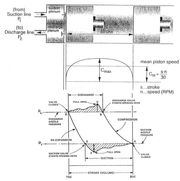
41. Piston position and card volume
The horizontal axis is often shown as volume, piston position, or percentage stroke.
For a single-acting cylinder:
- One dead centre corresponds to minimum volume.
- The opposite dead centre corresponds to maximum volume.
For a double-acting cylinder, the head-end and crank-end cards represent separate working spaces and may be compared for balance.
A card does not simply show time. It shows pressure at each cylinder volume.
42. Area inside the card
The enclosed p-V area represents indicated work.
W=oint P,dV
The actual area includes:
- Compression work
- Discharge-flow losses
- Suction-flow losses
- Valve opening and closing effects
- Leakage effects
- Pulsation distortion
The indexed maintenance text identifies the main enclosed area as compression work and separate areas as energy spent operating valves and overcoming flow resistance.
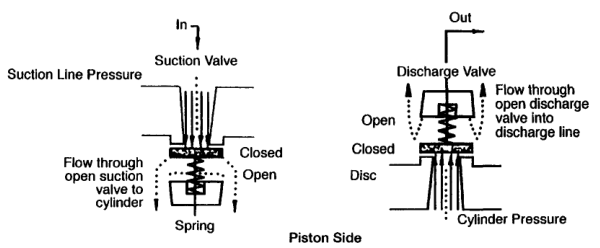
A larger card area means more work per cycle, provided the same sign convention and scale are used.
43. Ideal card versus actual card
Ideal card
Assumptions:
- No valve pressure drop
- Instantaneous valve action
- No leakage
- Smooth suction and discharge pressure
- Known compression law
- No pulsation
Actual card
Includes:
- Suction pressure loss
- Discharge pressure loss
- Valve inertia
- Delayed opening or closing
- Reverse flow
- Ring leakage
- Pulsation
- Clearance effects
- Heat transfer
The actual card is the useful diagnostic object; the ideal card is the reference pattern.
44. Suction line on an actual card
The actual cylinder suction pressure may be below suction-flange pressure because gas must pass through:
- Filter
- Suction pipe
- Suction valve
- Valve plate passages
- Cylinder ports
This pressure loss appears as a lower suction line on the card.
Possible causes of excessive suction loss:
- Dirty intake filter
- Small suction pipe
- Restricted silencer
- Stiff or damaged valve spring
- Broken valve plate
- Deposits
- High gas velocity
- Pulsation
45. Discharge line on an actual card
The actual cylinder discharge pressure may be above discharge-flange pressure because gas must pass through:
- Discharge valve
- Valve passage
- Cylinder port
- Discharge nozzle
- Pulsation bottle
- Discharge pipe
Possible causes of excessive discharge loss:
- Fouled valve
- Damaged valve plate
- Weak or incorrect spring
- Restricted port
- Fouled cooler
- Small discharge piping
- High gas velocity
- Pulsation or resonance
Excessive discharge loss increases cylinder work and temperature.
46. Re-expansion-line interpretation
The re-expansion line begins after discharge-valve closure.
It is controlled mainly by:
- Clearance volume
- Trapped-gas pressure
- Re-expansion exponent
- Piston motion
- Leakage through valves or rings
A longer re-expansion region means less fresh gas enters.
Possible causes of increased re-expansion:
- Excessive clearance
- Open clearance pocket
- Increased compression ratio
- Discharge valve closing late
- High discharge pressure
47. Clearance effect on the card
Increasing clearance changes the card by moving suction-valve opening toward the end of the return stroke.
Consequences:
- Shorter effective suction line
- Lower volumetric efficiency
- Lower capacity
- Possible lower total power at the same speed
- Different re-expansion shape
A clearance-pocket card may intentionally show this pattern during capacity control.
48. Suction-valve leakage pattern
A leaking suction valve may allow high-pressure gas to return toward the suction side during compression.
Expected effects:
- Compression line may rise abnormally slowly.
- Suction pressure may be disturbed.
- Capacity falls.
- Suction-valve cover may become hot.
- Incoming gas may be heated.
- Specific power rises.
A leaking suction valve can resemble ring leakage on a card. Confirm with temperature, valve inspection, and comparison with the opposite cylinder end.
49. Suction-valve restriction pattern
A restricted suction valve may cause:
- Low cylinder suction pressure
- Large suction-pressure loss
- Reduced cylinder filling
- Low capacity
- High suction-valve temperature
- Increased inlet velocity
The card may show a suction line substantially below the suction-flange pressure.
Possible causes:
- Broken plate
- Deposits
- Incorrect spring
- Poor lift
- Foreign material
- Fouled filter upstream
50. Discharge-valve leakage pattern
A leaking discharge valve may allow discharge gas to return into the cylinder after the discharge event.
Expected effects:
- Compression line or discharge corner becomes abnormal.
- Discharge temperature rises.
- Capacity falls.
- Valve cover becomes hot.
- Motor power may rise.
- Recompression occurs.
If the valve leaks severely, pressure may fail to hold at the expected discharge line.
51. Discharge-valve restriction pattern
A restricted discharge valve delays gas delivery.
Expected effects:
- Cylinder pressure rises above normal before valve opening.
- Discharge line lies above expected line pressure.
- Discharge temperature rises.
- Card area increases.
- Capacity falls.
- Valve cover may overheat.
This is a high-risk condition because high temperature can accelerate deposit formation and valve damage.
52. Piston-ring leakage pattern
Piston-ring leakage allows gas to pass across the piston.
Expected effects:
- Compression line may be less steep.
- Capacity falls.
- Cylinder temperature rises.
- Discharge temperature rises.
- Crankcase or opposite-end pressure may increase.
- Specific power rises.
Ring leakage is greatest when pressure difference is high and the piston is near the end of its stroke.
A card alone cannot quantify ring wear reliably; use leakage tests and temperature comparison.
53. Excessive clearance versus ring leakage
| Feature | Excessive clearance | Ring leakage |
|---|---|---|
| Main effect | Long re-expansion | Gas bypasses piston |
| Suction opening | Delayed | May be near normal |
| Capacity | Reduced | Reduced |
| Temperature | May be normal or elevated | Usually elevated |
| Crankcase pressure | Usually normal | May increase |
| Card pattern | Longer 3–4 line | Distorted compression line |
| Check | Bumping clearance | Leakage and ring condition |
Both faults can coexist.
54. Discharge-valve pulsation
Pulsation can hold a discharge valve open or cause it to close abnormally.
Possible consequences:
- Gas returns to the cylinder.
- Valve plate impacts the seat.
- Discharge temperature increases.
- Card discharge line becomes irregular.
- Valve fatigue accelerates.
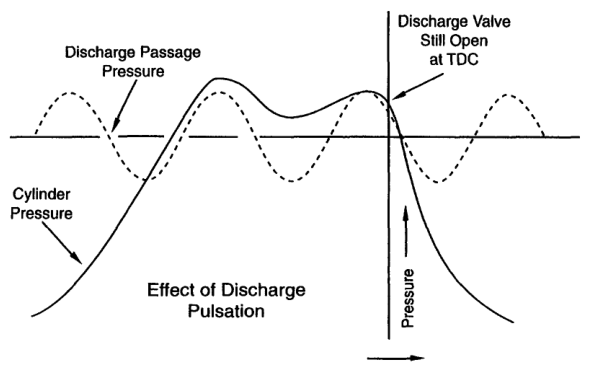
Pulsation-control changes should be assessed with the machine at the affected operating condition.
55. Actual card and horsepower
The card area can be used to estimate indicated horsepower:
IP=card work per cycle×cycles per second
For a double-acting cylinder, calculate the head-end and crank-end work separately and add them.
The result must be corrected or interpreted with:
- Indicator calibration
- Pressure-reference accuracy
- Volume scale
- Cylinder geometry
- Speed
- Gas leakage
- Card distortion
A larger card does not necessarily mean more useful air delivery. A leaking or restricted cylinder can draw high power while delivering little gas.
56. Card area and valve loss
The ideal card assumes gas enters and leaves without pressure loss.
Actual valve losses add work:
- Suction pressure is lower than flange pressure.
- Discharge pressure is higher than flange pressure.
- The compression loop becomes wider.
- Indicated work rises.
Valve loss depends on:
- Gas density
- Gas molecular weight
- Valve area
- Piston speed
- Port geometry
- Valve lift
- Pulsation
The compressor reference identifies gas density and valve velocity as major fluid-loss factors.
57. Card comparison between cylinder ends
For a double-acting cylinder, compare:
- Head-end card
- Crank-end card
- Suction pressure
- Discharge pressure
- Re-expansion
- Valve timing
- Card area
A large difference may indicate:
- One valve fault
- Different clearance
- Piston-ring leakage
- Packing problem
- Rod alignment issue
- Cylinder cooling difference
- Instrument-channel error
Use the same pressure and volume calibration for both ends.
58. Card comparison between stages
In a multistage compressor compare:
- LP-stage card
- HP-stage card
- Interstage pressure
- Stage discharge temperatures
- Stage capacity
- Stage work
A weak LP card may cause low interstage pressure.
A weak HP card may cause high interstage pressure.
Unequal card area suggests unequal stage work and may explain vibration or temperature differences.
59. Card patterns and likely faults
| Card observation | Likely direction |
|---|---|
| Long re-expansion | Excessive clearance or high ratio |
| Low suction line | Suction restriction or valve loss |
| High discharge line | Discharge restriction or valve loss |
| Slow compression rise | Suction leakage, ring leakage, unloader |
| Irregular discharge line | Pulsation, chatter, discharge valve fault |
| Card area high | Excess work, valve loss, leakage, high ratio |
| Card area low with low capacity | Unloading, low suction density, severe filling loss |
| Head/crank ends unequal | Local valve, ring, clearance, or packing problem |
| Card changes with piping condition | Pulsation or resonance |
These are screening directions, not final diagnoses.
60. Card repeatability
A healthy cylinder operating at stable conditions should produce repeatable cards.
Poor repeatability may indicate:
- Pulsation
- Valve chatter
- Unstable unloaders
- Control cycling
- Loose sensor connection
- Mechanical looseness
- Intermittent liquid carryover
- Variable suction or discharge pressure
Capture multiple cycles and compare the spread.
One abnormal cycle may be noise; a repeatable abnormal pattern is more significant.
61. Indicator-card example: low capacity
Observation
- Capacity low
- Motor power normal
- Long re-expansion line
- Suction and discharge lines otherwise smooth
Likely direction
Excessive clearance or open clearance pocket.
Checks
- Capacity-control position
- Bumping clearance
- Cylinder-head gasket or shim condition
- Compression ratio
- Piston position
62. Indicator-card example: high power
Observation
- Capacity slightly low
- Motor power high
- Discharge line above normal
- Discharge temperature high
Likely direction
Discharge-valve restriction or high discharge pressure.
Checks
- Discharge valve and spring
- Discharge passage
- Cooler and piping
- Receiver pressure
- Pressure-gauge calibration
63. Indicator-card example: ring leakage
Observation
- Compression line rises slowly
- Capacity low
- Cylinder temperature high
- Crankcase pressure elevated
- No major suction-line restriction
Likely direction
Piston-ring leakage.
Checks
- Ring condition
- Cylinder bore
- Ring end gap
- Ring orientation
- Lubrication
- Blow-by measurement
64. Indicator-card example: pulsation
Observation
- Card has waves on suction and discharge lines
- Pattern changes with speed
- Valve-cover temperatures are similar
- Piping vibrates at the same operating speed
Likely direction
Pulsation or piping resonance rather than a single valve failure.
Checks
- Pulsation bottle condition
- Nozzle size and length
- Pipe supports
- Operating speed
- Acoustic resonance
- Pressure traces at different locations
65. Indicator-card example: stage imbalance
Observation
- LP card area is high
- Interstage pressure is high
- HP card area is low
- Final capacity is low
Likely direction
HP stage is not accepting or compressing gas effectively.
Checks
- HP suction valve
- HP cylinder clearance
- HP piston rings
- Interstage passage
- HP discharge valve
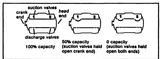
66. Clearance-control card
When a clearance pocket is opened:
- Re-expansion line extends.
- Point 4 moves toward the end of the stroke.
- Effective suction volume decreases.
- Capacity falls.
- Card shape changes intentionally.
A control-system card must be compared with the correct load-state reference, not with the full-load card.
67. Safe use of indicator equipment
Before connecting or removing instrumentation:
- Isolate the cylinder if required.
- Depressurise the correct chamber.
- Confirm sensor pressure rating.
- Use compatible fittings.
- Prevent hot-gas exposure.
- Route cables away from moving parts.
- Verify crank-angle pickup.
- Keep personnel clear during operation.
After testing:
- Remove temporary connections safely.
- Restore plugs and seals.
- Check for leaks.
- Confirm the compressor is ready for service.
68. Volumetric Efficiency Defined & The Physical Reality of Cylinder Displacement
A fundamental operational question encountered by marine engineers is: If an air compressor piston has a bore of 150 mm and a stroke of 120 mm, running at 600 RPM, why doesn't it deliver its full theoretical geometric displacement into the ship's air bottles?
To understand the answer, we must clearly define and distinguish Piston Displacement from Actual Delivered Capacity:
A. Piston Displacement (Swept Volume Rate)
Piston Displacement (PD) is the purely geometric volume swept through by the piston face per unit time during its motion from Top Dead Center (TDC) to Bottom Dead Center (BDC):
Cylinder Swept Volume (Displacement per Stroke)
Vs = π4 × D2 × L
Where D = Cylinder Bore (m), L = Piston Stroke Length (m)
Geometric Piston Displacement Rate
PD = Vs × N × Z
Where N = Speed (RPM / strokes per min), Z = Number of Cylinders
Piston displacement is an unchangeable geometric property of the metal castings and crankshaft throw. It represents the maximum volume that could be swept if the cylinder were an empty, ideal pump.
B. Actual Free Air Delivery (FAD) & Volumetric Efficiency
In reality, the volume of fresh atmospheric air drawn into the cylinder during every suction stroke and delivered to the receiver is always significantly less than the geometric swept volume. The ratio between these two quantities is called the Volumetric Efficiency (ηv):
Volumetric Efficiency Definition
ηv = Qactual (Actual Free-Air Inhaled at P1, T1)PD (Geometric Piston Displacement) × 100%
Measures the true cylinder filling capacity of the compressor
C. Distinguishing the Three Essential Compressor Efficiencies
Marine competency examinations frequently test an engineer's ability to differentiate the three distinct efficiency metrics of a compressor. Confusing them is a common failure point:
| Efficiency Metric | Mathematical Definition | What It Measures Physically | Typical Range |
|---|---|---|---|
| Volumetric Efficiency (ηv) | Qactual / PD | Pumping effectiveness: Measures how effectively the cylinder fills its swept volume with fresh suction charge, accounting for clearance re-expansion, valve throttling, and thermal heating. | 70% to 85% |
| Isothermal Efficiency (ηiso) | Wisothermal / Windicated | Cooling perfection: Compares the actual indicated power on the piston to the theoretical minimum power required by an ideal isothermal cycle at suction temperature. | 65% to 75% |
| Mechanical Efficiency (ηm) | Windicated / Wshaft,brake | Frictional losses: Measures mechanical power lost in crankshaft main bearings, crankpins, gudgeon pin bushes, piston ring drag, and crosshead guides. | 85% to 92% |
69. Clearance Volume & The Thermodynamics of Re-Expansion
Key Symbol & Variable Definitions
- ηv (Volumetric Efficiency): The ratio of actual volume of free air drawn into the cylinder per stroke to the geometric swept volume of the cylinder.
- Vs (Swept Volume): The physical displacement volume swept by the piston face from Top Dead Center (TDC) to Bottom Dead Center (BDC).
- Vc (Clearance Volume): The residual dead space volume remaining above the piston crown and in valve pockets when the piston reaches Top Dead Center (TDC).
- c (Clearance Ratio): The clearance volume expressed as a fraction of swept volume (c = Vc / Vs, typically 4% to 10%).
- Veff (Effective Suction Volume): The actual fresh intake portion of the stroke from Point 4 to Point 1 (after clearance gas has finished re-expanding).
- P1 & P2 (Suction & Delivery Pressures): Absolute intake pressure (P1) and absolute discharge pressure (P2).
- n (Polytropic Index): Thermodynamic expansion exponent of the air (typically ~1.3).
By far the single greatest cause of lost volumetric capacity in a properly operating reciprocating compressor is Clearance Volume (Vc) and the unavoidable phenomenon of clearance gas re-expansion.
A. What Constitutes Clearance Volume?
When the compressor piston reaches the absolute end of its upward stroke at Top Dead Center (TDC), the cylinder volume is not zero. A residual dead space remains, known as the Clearance Volume (Vc). This volume consists of three components:
- Linear Bumping Clearance: The mechanical safety gap between the top surface of the piston crown and the underside of the cylinder cover (typically 0.5 mm to 1.5 mm).
- Valve Pockets & Port Passages: The hollow recesses and annular flow passages machined into the cylinder head beneath the suction and discharge valve assemblies.
- Piston Ring Land Cavity: The annular radial crevice between the outside diameter of the piston crown and the inside diameter of the cylinder liner down to the topmost compression ring.
The Clearance Ratio (c) is defined as the clearance volume expressed as a fraction of the piston swept volume:
Clearance Ratio Definition
c = VcVs
Typically 0.04 to 0.10 (4% to 10% of swept volume) in marine reciprocating machines
B. The Re-Expansion Process on the P-V Indicator Diagram
To see how clearance volume directly steals suction capacity, let us trace the compressor cycle on a Pressure-Volume indicator diagram:
Step-by-Step Cycle Walkthrough:
- Point 1 to Point 2 (Compression Stroke): The piston moves upward from BDC (Point 1). The suction valve closes. Air trapped in volume V1 (where V1 = Vs + Vc) is compressed polytropically along curve P · V^n = C until cylinder pressure slightly exceeds the receiver pressure P2.
- Point 2 to Point 3 (Discharge Stroke): At Point 2, the discharge valve opens against its spring. The piston forces compressed air out of the cylinder into the discharge pipe at pressure P2 until reaching TDC (Point 3).
- Point 3 (Top Dead Center): The discharge valve snaps shut under spring force. The cylinder is NOT empty! The clearance volume Vc is completely filled with residual air at the full discharge pressure P2.
- Point 3 to Point 4 (The Re-Expansion Loss): The piston reverses direction and begins its downward suction stroke. Can fresh atmospheric air enter the cylinder immediately? ABSOLUTELY NOT!
The cylinder pressure at Point 3 is P2 (e.g. 5.5 bar or 30 bar), while the atmospheric suction line is at P1 (1.0 bar). The suction valve is held firmly closed against its seat by the massive internal cylinder pressure. Before the suction valve can open, the trapped high-pressure clearance gas must re-expand along curve 3 → 4 (following P · V^n = C) until the internal cylinder pressure drops below suction pressure P1.
- Point 4 to Point 1 (The True Suction Intake): Only when the piston reaches Point 4 does cylinder pressure fall slightly below atmospheric pressure, allowing the suction valve spring to overcome pressure and pop open! Fresh atmospheric air is drawn into the cylinder only during the remainder of the stroke from Point 4 to Point 1.
The piston has traveled a physical distance from Point 3 to Point 4 without inhaling a single cubic millimeter of fresh atmospheric air! This lost stroke distance is completely stolen by clearance re-expansion.
70. Mathematical Derivation of Volumetric Efficiency
Let us now derive the universal thermodynamic equation for compressor volumetric efficiency directly from first principles, demonstrating how clearance ratio and compression ratio govern machine capacity.
A. Rigorous Step-by-Step Derivation
-
Polytropic Re-Expansion Law:
The clearance gas trapped at Point 3 (volume V3 = Vc at pressure P3 = P2) expands along a polytropic path to Point 4 (volume V4 at pressure P4 = P1):
General Polytropic Relation: P3 × V3n = P4 × V4n
Substituting Endpoints (V3 = Vc, P3 = P2, P4 = P1): P2 × Vcn = P1 × V4n
-
Solve for Re-Expanded Volume (V4):
Rearranging the polytropic relation gives:
Ratio Form: (V4 / Vc)n = P2 / P1
Solving for V4: V4 = Vc × (P2 / P1)1n
-
Calculate Effective Fresh-Air Intake Volume (Veff):
The volume of fresh air drawn in during the suction stroke from Point 4 to Point 1 is:
Veff = V1 − V4
Since total cylinder volume at BDC is the sum of swept volume and clearance volume (V1 = Vs + Vc):Step A (Substitute V1): Veff = (Vs + Vc) − V4
Step B (Substitute V4): Veff = Vs + Vc − Vc × (P2 / P1)1n
Step C (Factor out Vc): Veff = Vs − Vc × [ (P2 / P1)1n − 1 ]
-
Derive Theoretical Volumetric Efficiency (ηv):
By definition, theoretical volumetric efficiency is effective suction volume divided by swept volume:
ηv = VeffVs = Vs − Vc × [ (P2 / P1)1n − 1 ]Vs
Dividing through by Vs and substituting the clearance ratio c = Vc / Vs:The Fundamental Volumetric Efficiency Formula
ηv = 1 − c × [ (P2 / P1)1n − 1 ]
Directly proves that volumetric efficiency falls as clearance (c) or pressure ratio (P₂/P₁) rises!
B. Physical Analysis: The Two Enemies of Volumetric Efficiency
Examine the mathematical formula closely. It reveals exactly how two variables dictate volumetric efficiency:
- 1. The Compression Ratio (P2 / P1): As delivery pressure P2 increases relative to suction pressure P1, the term (P2 / P1)1/n grows exponentially. As seen in Figure 3, higher pressure forces the re-expansion curve further and further to the right across the stroke, stealing more and more of the suction stroke.
- 2. The Clearance Ratio (c): The clearance ratio acts as a multiplier. If clearance volume is doubled (due to incorrect gasket thickness or excessive bumping clearance), the loss term doubles in magnitude, causing volumetric efficiency to plummet!
Comparative Numerical Proof: Why Staging is Mandatory
Consider a compressor with a typical clearance ratio c = 6% (0.06) and polytropic index n = 1.3:
Case A: Single-Stage Compression from 1 bara to 31 bara (Ratio 31:1)
ηv = 1 − 0.06 × [ (31)11.3 − 1 ] = 1 − 0.06 × [14.07 − 1] = 1 − 0.784 = 21.6%
Clearance re-expansion steals nearly 80% of the stroke! A slight wear in rings or valves reduces delivery to ZERO.
Case B: Two-Stage Compression (Stage Ratio = 5.57:1)
ηv = 1 − 0.06 × [ (5.57)11.3 − 1 ] = 1 − 0.06 × [3.73 − 1] = 1 − 0.164 = 83.6%
Multistaging quadruples volumetric efficiency, recovering 62% of lost intake stroke!
71. Capacity is meaningful only with conditions
Compressor capacity is not a single universal number.
A flow rate must identify:
- Gas or air composition
- Suction pressure
- Suction temperature
- Humidity
- Discharge pressure
- Flow-meter location
- Mass or volume basis
- Standard or actual reference condition
- Loaded or unloaded state
- Compressor speed
The same machine can produce different volumetric readings at different suction temperatures and pressures while processing nearly the same mass flow.
Always ask:
Capacity at what pressure, temperature, gas condition, and location?
72. Actual capacity
Actual capacity is often expressed at compressor intake conditions.
Common terms include:
- ACFM: actual cubic feet per minute
- ICFM: intake cubic feet per minute
- FAD: free-air delivery
- SCFM: standard cubic feet per minute
- Normal m³/min: volume referred to a specified normal condition
- Mass flow: kg/s or kg/h
The compressor reference identifies actual capacity with ICFM or ACFM and distinguishes it from piston displacement.
For a reciprocating compressor:
Qactual=PD×η_v
where η_v includes clearance and practical filling losses.
73. Free-Air Delivery (FAD) Calculation & Effective Capacity
Free-air delivery is the equivalent volume of delivered gas referred to an agreed reference condition, commonly near atmospheric pressure and a specified temperature.
It is useful because the actual discharge volume is small at high pressure, while the equivalent free-air quantity describes the amount of air processed.
The reference condition must be stated. Different standards may use different:
- Atmospheric pressure
- Temperature
- Humidity
- Unit definitions
Never compare two “free-air” ratings without checking their reference conditions.
74. Actual volume versus mass flow
For an ideal gas:
dotm=ρ Q
and:
ρ=P/RT
Therefore:
dotm=P Q/RT
At higher suction pressure, the same actual volume contains more mass.
At higher suction temperature, the same actual volume contains less mass.
This explains why actual volumetric flow alone can be misleading when comparing compressors installed at different locations or operating under different intake conditions.
75. Converting actual volume between conditions
For the same gas mass, neglecting compressibility variation:
P₁ Q₁/T₁=P₂ Q₂/T₂
Therefore:
Q₂=Q₁P₁/P₂T₂/T₁
Use absolute pressure and absolute temperature.
For real gases, include compressibility factor:
P₁Q₁/Z₁T₁=P₂Q₂/Z₂T₂
Air at moderate pressure can often be approximated as ideal, but process gases may require Z.
76. Capacity example: actual to standard basis
A compressor draws 100 m³/min at:
- Suction pressure = 1.05 bara
- Suction temperature = 303 K
Find the equivalent volume at 1.00 bara and 293 K, assuming ideal gas.
Q₂=100×1.05/1.00×293/303
Q₂≈101.6 m³/min
The numerical result changes if humidity, compressibility, or another standard basis is specified.
77. Capacity and volumetric efficiency
Volumetric efficiency is:
η_v=Qactual/PD×100%
Capacity falls when:
- Clearance increases
- Compression ratio increases
- Suction temperature rises
- Suction pressure falls
- Valves leak
- Rings leak
- Intake passages restrict flow
- Capacity-control devices unload the cylinder
A capacity guarantee must state the expected volumetric efficiency or the complete operating conditions.
78. Effect of speed on capacity and power
At moderate conditions:
PD∝ N
Capacity tends to increase with speed.
Power also tends to increase because more gas is compressed per unit time.
At high speed, proportionality fails because:
- Valve losses increase
- Volumetric efficiency may fall
- Heating increases
- Piston and ring friction increase
- Pulsation increases
- Lubrication and cooling limits are reached
Never increase speed beyond the manufacturer’s rated range to recover lost capacity before checking the underlying fault.
79. Capacity and power trend table
| Trend | Likely interpretation |
|---|---|
| Capacity down, power down | Clearance increase, unloading, low suction density |
| Capacity down, power up | Valve leakage, ring leakage, restriction, high ratio |
| Capacity stable, power up | Mechanical friction, cooling loss, pressure increase |
| Capacity up, power up | Increased speed or demand; verify limits |
| Capacity stable, motor current up | Discharge pressure, voltage, power factor, mechanical loss |
| Interstage pressure low | Preceding-stage capacity loss |
| Interstage pressure high | Succeeding-stage capacity loss or restriction |
| Discharge temperature high | Cooling fault, valve loss, ratio, leakage |
| Specific power rising | Overall efficiency deterioration |
80. Selection from capacity and power data
A compressor selection must satisfy:
- Required mass flow
- Required standard or actual volume flow
- Suction-pressure range
- Discharge-pressure range
- Gas composition
- Temperature limits
- Driver availability
- Part-load range
- Cooling-water availability
- Maintenance capability
- Safety and certification requirements
Do not select solely from the maximum flow number.
The machine must deliver the required flow at the required pressure with acceptable power and temperature.
81. Lifecycle power cost
Power cost is often the largest part of compressed-air cost over the machine’s life.
Lifecycle assessment should include:
- Motor power
- Operating hours
- Electricity or fuel cost
- Cooling auxiliaries
- Maintenance
- Spare parts
- Downtime
- Part-load operation
- Leakage in the distribution system
A more expensive compressor with better specific power may be cheaper over its service life.
The compressor reference stresses that lifetime power cost can greatly exceed initial purchase cost.
82. Capacity staging in multiple compressors
When several compressors operate in parallel:
- Lead unit may run near efficient load.
- Additional units start as demand rises.
- Units stop as demand falls.
- Pressure band determines sequencing.
Poor sequencing can cause:
- Several units lightly loaded
- Repeated start-stop cycles
- Unnecessary blow-off
- High specific power
- Unequal running hours
A good sequence maintains required pressure with the fewest efficient units online.
83. Free air and standard air
Free air generally means air at normal atmospheric conditions, but it is not identical everywhere.
Atmospheric pressure, temperature, and altitude vary.
Therefore, “free air” must be linked to reference conditions.
The compressor reference warns that the terms free air and standard air are not necessarily interpreted identically by every user because local pressure and temperature conditions vary.
When reading a compressor rating, identify:
- Reference suction pressure
- Reference suction temperature
- Relative humidity, if specified
- Reference discharge pressure
- Measurement location
- Whether capacity is mass flow or volumetric flow
84. Effect of intake temperature on capacity
At constant suction pressure:
ρ ∝ 1/T
If intake temperature rises:
- Density decreases.
- Less mass enters per swept volume.
- Mass delivery decreases.
- Volumetric capacity expressed at intake conditions may appear similar, but mass capacity falls.
- Compression power and temperature behaviour may change.
Example
Compare air at 20°C and 40°C at the same pressure.
ρ₄₀/ρ₂₀ = 293.15/313.15 ≈ 0.936
The air at 40°C has approximately 93.6% of the density at 20°C.
This is why cool, clean intake air improves compressor mass delivery.
85. Air properties and compressor capacity
For a given displacement:
m = ρ V
Since:
ρ = p/RT
then:
m = pV/RT
Therefore delivered mass changes if:
- Suction pressure changes.
- Suction temperature changes.
- Gas composition changes.
- Compressor displacement changes.
- Volumetric efficiency changes.
This is why compressor capacity must specify reference conditions.
86. Ideal p-V cycle interpretation
Position 1
Cylinder is filled with gas at suction pressure.
Position 1 to 2
Piston compresses gas. Suction valve is closed.
Position 2
Cylinder pressure reaches discharge pressure. Discharge valve opens.
Position 2 to 3
Compressed gas leaves the cylinder.
Position 3
Piston reaches the end of discharge. Clearance gas remains.
Position 3 to 4
Clearance gas expands as piston returns.
Position 4
Cylinder pressure falls below suction pressure. Suction valve opens.
Position 4 to 1
Fresh gas enters.
Found a mistake, or something unclear?
Report it in a few seconds — it goes straight to the editors.
- Air Compressor Principle, Thermodynamics & Multistage Advantages
- Air Compressor Types & Classification
- Air Compressor Construction — Pistons, Rings, Valves & Running Gear
- Air Compressor Working — Cycle, Volumetric Efficiency, Coolers & Capacity
- Air Compressor Operations — Lubrication, Drains & Running
- Air Compressor Maintenance — Lapping, Clearances & Overhaul
- Air Compressor Safety — Relief Devices, Receivers & SOLAS
- Air Compressor Troubleshooting — Interstage Pressure & Fault Finding