

Air Compressor Principle, Thermodynamics & Multistage Advantages
Marine starting-air thermodynamics: absolute pressure and Kelvin rules, isothermal vs adiabatic vs polytropic paths, why single-stage 31:1 fails (400C
1. The shortest definition
A compressor is a machine that receives air or another gas at a lower pressure and delivers it at a higher pressure.
It does this by supplying mechanical energy to the gas.
In that chain, mechanical power drives the compressor, work is done on the gas, the compressor changes its pressure, density and temperature, and the higher-pressure gas is delivered to a receiver, equipment, a process or an engine system. The compressor does not create air — it changes the condition of it.
The compressor does not create air. It changes the pressure, density, temperature, and useful condition of air.
The main compressor reference describes compressors as machines used to move air and other gases from place to place. Because gases are compressible, compressors operate differently from liquid pumps.
2. Why air can be compressed
Air is a gas made of molecules separated by spaces.
When air is enclosed in a cylinder and the piston moves inward:
- The available volume decreases.
- The molecules occupy a smaller space.
- Molecular collisions with the cylinder wall increase.
- The pressure rises.
- The temperature generally rises because work has been done on the gas.
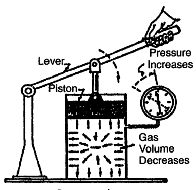
The indexed compressor text explains that reducing gas volume increases pressure and also increases temperature.
3. What a compressor changes
When air passes through a compressor, several properties change:
- Pressure increases.
- Volume decreases for a trapped mass of gas.
- Density increases.
- Temperature increases during compression.
- Moisture may later condense during cooling.
- Mechanical energy becomes gas internal energy and pressure potential.
6.1 Pressure
Pressure is the force exerted by gas on a unit area.
For a gas inside a receiver, pressure represents stored energy that can perform work when released.
6.2 Volume
Volume is the space occupied by the gas.
A compressor cylinder repeatedly traps a volume of gas, reduces that volume, and delivers the gas at higher pressure.
6.3 Density
Density is mass per unit volume.
For the same mass of air:
- Higher pressure generally means greater density.
- Lower temperature generally means greater density.
- Higher density means more mass can be stored in a receiver of fixed volume.
6.4 Temperature
Compression raises temperature because mechanical work is transferred to the gas.
This is why compressors need:
- Cylinder cooling
- Intercoolers
- Aftercoolers
- Temperature alarms
- Condensate drains
4. Pressure terminology
A correct foundation requires clear pressure definitions.
7.1 Atmospheric pressure
Atmospheric pressure is the pressure exerted by the surrounding atmosphere.
It changes with:
- Altitude
- Weather
- Temperature
7.2 Gauge pressure
Gauge pressure is pressure above local atmospheric pressure.
A gauge reading of zero does not mean the system contains no pressure in an absolute sense. It means the pressure is approximately equal to the surrounding atmosphere.
7.3 Absolute pressure
Absolute pressure is measured from a perfect vacuum.
Pabsolute = Pgauge + Patmospheric
Absolute pressure must be used for:
- Pressure ratios
- Gas-law calculations
- Compressor performance calculations
- Stage-ratio calculations
7.4 Vacuum pressure
Vacuum pressure describes pressure below atmospheric pressure.
It is often expressed as:
- Inches of mercury
- Millimetres of mercury
- kPa below atmospheric pressure
- Absolute pressure directly
The compressor reference warns that the word “absolute” should not be omitted when a vacuum or pressure is stated.
5. Gauge pressure versus absolute pressure example
Suppose a receiver gauge reads 30 bar gauge and local atmospheric pressure is approximately 1 bar.
Pabsolute ≈ 30 + 1 = 31 bar absolute
If a compressor suction pressure is 1 bar absolute and discharge pressure is 31 bar absolute:
Pressure ratio = 31/1 = 31
Using 30 bar gauge directly would produce a slightly incorrect ratio.
The error becomes more important at lower pressures and when comparing compressor stages.
6. Displacement: the volume swept by the piston
Piston displacement is the volume swept by the piston while moving through its stroke at rated speed.
For one cylinder, the swept volume per stroke is approximately:
Vs = π × D² / 4 × L
where:
- D = cylinder bore
- L = piston stroke
For a single-acting cylinder, ideal displacement per minute is approximately:
Vdisp = Vs × N
where:
- N = number of working strokes per minute
For a double-acting cylinder, both sides contribute, subject to piston-rod area and actual design.
Important limitation
Piston displacement is not the same as actual free-air delivery.
Actual delivery is reduced by:
- Clearance
- Valve losses
- Leakage
- Heating of inlet air
- Piston-ring blow-by
- Pressure ratio
- Flow restrictions
The compressor reference explains that capacity varies with pressure conditions and that piston displacement alone does not represent actual delivered air.
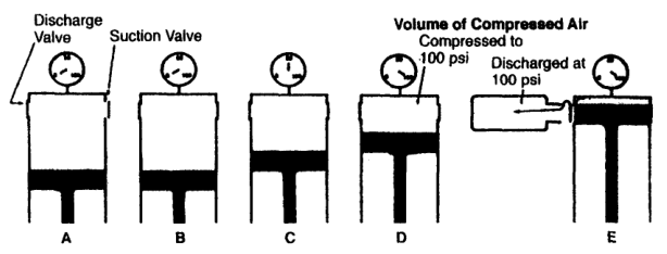
7. Capacity is not a fixed number
A compressor’s practical capacity changes with operating conditions.
For the same compressor and inlet condition:
- Higher discharge pressure usually reduces delivered capacity.
- Higher inlet temperature reduces air mass admitted per swept volume.
- Dirty valves reduce delivery.
- High clearance reduces delivery.
- Piston-ring leakage reduces delivery.
- Lower speed reduces displacement per minute.
This is why compressor ratings state the reference inlet and discharge conditions.
Capacity terms
- Piston displacement: geometric swept volume.
- Theoretical capacity: ideal volume based on displacement.
- Free-air delivery: equivalent volume referred to inlet or standard conditions.
- Actual delivered volume: volume at the pressure and temperature where it is measured.
- Mass flow: actual mass of air delivered per unit time.
8. Free-Air Delivery (FAD) Concept & Atmospheric Basis
Free-air delivery expresses compressed air as the volume it would occupy at specified inlet or reference conditions.
It allows different compressors to be compared fairly.
Without a reference condition, a statement such as “the compressor delivers 10 m³/min” is incomplete because the same mass of air occupies different volumes at different pressures and temperatures.
Always ask:
- At what inlet pressure?
- At what inlet temperature?
- Is the value actual volume or free-air volume?
- Is it measured before or after the cooler?
- Is it at full load or part load?
9. Why compression produces heat
Work is required to reduce gas volume and raise pressure.
That work appears partly as increased gas internal energy.
Therefore:
The work has to go somewhere, and it appears as internal energy of the gas. Pressure and temperature therefore rise together, and cooling is required: without it the lubricant, the valves and the material suffer.
High temperature creates several problems:
- Lubricant breakdown
- Valve deposits
- Reduced valve life
- Cylinder wear
- Higher discharge-piping fire risk
- Increased power requirement
- Material damage
The compressor reference explains that high compression temperatures create design and operating limits.
10. Why multistage compression is used
A single stage can compress gas only within practical limits.
Multistaging divides the total pressure rise:
Benefits:
- Lower discharge temperature per stage
- Lower work than equivalent uncooled single-stage compression
- Improved volumetric efficiency
- Better mechanical and lubrication conditions
- Easier moisture removal between stages
- More practical high-pressure production
A stage should not be judged by discharge pressure alone. Interstage pressure reveals whether stages are sharing the work correctly.
11. Why cooling is part of compression
Cooling is not an optional accessory added after the compressor design. It affects the complete process.
Cylinder cooling
Protects cylinder, piston, rings, and lubricant.
Intercooling
Removes heat between stages and reduces the temperature entering the next stage.
Aftercooling
Removes final-stage heat before air enters the receiver or distribution system.
Condensate removal
Cooling can cause water vapour to condense. Separators and drains must remove it.
The compressor reference identifies aftercoolers and moisture separators as important parts of the compressed-air system.
12. Absolute pressure
Absolute pressure is measured from perfect vacuum.
Common symbols:
- psia — pounds per square inch absolute
- bara — bar absolute
- kPaa — kilopascals absolute
- MPaa — megapascals absolute
Formula:
Pabsolute = Pgauge + Patmospheric
Absolute pressure is required for:
- Gas laws
- Compression ratios
- Thermodynamic calculations
- Stage pressure calculations
- Density calculations
- Free-air corrections
- Vacuum interpretation
Never write simply “100 psi” in a technical calculation if it is important whether the value is psig or psia.
13. Gauge and absolute pressure example
Problem
A compressor delivers air at 100 psig at sea level. Find approximate discharge pressure in psia.
Solution
At sea level:
Patmospheric ≈ 14.7 psi
Therefore:
Pdischarge,absolute = 100 + 14.7
Pdischarge,absolute = 114.7 psia
The compressor reference gives this same relationship when explaining a 100-psi-gauge air system.
Important
The answer is not 100 psia.
The gauge has omitted the atmospheric pressure because its zero is atmospheric.
14. Compression ratio
The overall compression ratio is:
rp = Pdischarge,absolute/Psuction,absolute
Both pressures must use the same absolute unit.
Example 1 — sea-level plant air
- Suction = 14.7 psia
- Discharge = 114.7 psia
rp = 114.7/14.7 ≈ 7.8
The compressor reference gives this approximate 7.8:1 example for 100 psig discharge at sea level.
Example 2 — bar units
- Suction = 1.0 bara
- Discharge = 9.0 bara
rp = 9.0/1.0 = 9.0
Incorrect method
Do not calculate:
100 psig/0 psig
A gauge reading of zero at atmospheric suction cannot be used as the denominator.
15. Interstage pressure
In a multistage compressor, interstage pressure is the pressure between stages, commonly measured at the intercooler or second-stage suction.
Interstage pressure shows whether the stages are sharing the compression work properly.
The compressor reference states that normal interstage pressure should be observed regularly because changes can identify valve or stage problems.
16. Stage pressure ratio
For a two-stage compressor:
roverall = r₁ × r₂
where:
- r₁ = first-stage absolute pressure ratio
- r₂ = second-stage absolute pressure ratio
For approximately equal stage ratios:
r₁ ≈ r₂ ≈ √(roverall)
Example
If overall pressure ratio is 16:
rstage ≈ √(16) = 4
The approximate intermediate absolute pressure is:
Pintermediate ≈ Psuction × 4
Actual values depend on cooling, valve condition, leakage, gas properties, and design.
17. Gauge-pressure calculation trap
Wrong calculation
A compressor takes air at “0 bar” and delivers at 8 bar. The operator calculates:
rp = 8/0
This is invalid because 0 bar gauge means approximately atmospheric pressure, not zero absolute pressure.
Correct calculation
Assuming atmospheric pressure ≈ 1 bar:
- Suction ≈ 1 bara
- Discharge ≈ 9 bara
rp = 9/1 = 9
18. Why the word “absolute” must not be omitted
Compare:
- 2 bar
- 2 bara
- 2 barg
These have different meanings.
At approximately 1 bar atmosphere:
- 2 bara ≈ 1 barg
- 2 barg ≈ 3 bara
The difference is operationally important.
A pressure-ratio error can lead to:
- Wrong power estimate
- Wrong temperature estimate
- Wrong stage sizing
- Wrong valve loading
- Wrong capacity estimate
- Wrong alarm settings
19. Absolute temperature
Gas-law calculations require absolute temperature.
The SI absolute temperature scale is Kelvin:
T(K) = T(°C) + 273.15
For Fahrenheit-to-Rankine conversion:
T(°R) = T(°F) + 459.67
Never use Celsius or Fahrenheit directly in a ratio such as:
T₂/T₁
Example
20°C and 40°C are not a temperature ratio of 40/20 = 2.
Convert first:
T₁ = 20 + 273.15 = 293.15 K
T₂ = 40 + 273.15 = 313.15 K
T₂/T₁ = 313.15/293.15 ≈ 1.068
The absolute-temperature ratio is approximately 1.068, not 2.
20. Boyle’s law
For a fixed mass of ideal gas at constant temperature:
pV = constant
Therefore:
p₁V₁ = p₂V₂
If volume decreases, pressure increases in inverse proportion.
Example
A gas occupies 1.0 m³ at 1 bara and is compressed isothermally to 0.5 m³.
p₁V₁ = p₂V₂
1.0 × 1.0 = p₂ × 0.5
p₂ = 2.0 bara
The refrigeration reference gives the same principle: when volume is reduced to half at constant temperature, pressure doubles.
21. Charles’ law
At constant pressure, the volume of a fixed mass of ideal gas is proportional to absolute temperature:
V₁/T₁ = V₂/T₂
or:
V ∝ T
If gas is heated at constant pressure, it expands.
If gas is cooled at constant pressure, it contracts.
Example
A gas occupies 0.75 m³ at 20°C and is heated at constant pressure to 90°C.
Convert temperatures:
T₁ = 293.15 K
T₂ = 363.15 K
Then:
V₂ = V₁ × T₂/T₁
V₂ = 0.75 × 363.15/293.15
V₂ ≈ 0.93 m³
This worked example is given in the refrigeration reference.
22. Amonton’s law
At constant volume, pressure is proportional to absolute temperature:
p₁/T₁ = p₂/T₂
or:
p ∝ T
If a sealed receiver is heated, its pressure rises even though the amount of gas and volume remain constant.
Example
A sealed receiver contains air at:
- p₁ = 8 bara
- T₁ = 293.15 K
The temperature increases to 333.15 K.
p₂ = p₁ × T₂/T₁
p₂ = 8 × 333.15/293.15
p₂ ≈ 9.09 bara
This is why a receiver’s safety valve and temperature exposure must be considered even when the compressor is stopped.
23. Combined gas law
For a fixed mass of ideal gas:
p₁V₁/T₁ = p₂V₂/T₂
This combines Boyle’s, Charles’, and Amonton’s relationships.
Rearrangements include:
p₂ = p₁V₁/V₂T₂/T₁
V₂ = V₁p₁/p₂T₂/T₁
T₂ = T₁p₂V₂/p₁V₁
All pressure values must be absolute, and all temperature values must be absolute.
24. Ideal-gas equation
The combined gas law can be expressed as:
pV = mRT
where:
- p = absolute pressure
- V = gas volume
- m = gas mass
- R = specific gas constant
- T = absolute temperature
For air:
Rair ≈ 287 J/(kg· K)
The refrigeration reference gives the ideal-gas equation and a volume calculation for a known mass of gas.
Rearranged forms
m = pV/RT
V = mRT/p
p = mRT/V
T = pV/mR
25. Isothermal compression
Isothermal compression occurs at constant temperature.
pV = constant
The heat produced by compression is removed continuously.
This requires ideal or highly effective cooling.
Advantages
- Lowest theoretical compression work for a given pressure ratio
- Lowest final temperature
- Reduced thermal stress
Practical limitation
Perfect isothermal compression is difficult because heat transfer cannot be instantaneous throughout the cylinder.
It is a useful theoretical reference, not the exact real compressor cycle.
26. Adiabatic compression
Adiabatic compression occurs with no heat transfer to or from the gas during the compression process.
For an ideal gas:
pV^k = constant
where k is the ratio of specific heats.
Adiabatic compression produces a larger temperature rise than isothermal compression for the same pressure ratio.
The compressor reference defines adiabatic compression as compression without heat transfer.
Practical meaning
A fast compression stroke behaves closer to adiabatic than isothermal because there is little time for heat to leave the gas during the stroke.
27. Polytropic compression
Polytropic compression follows:
pV^n = constant
where n is the polytropic exponent.
The value of n depends on heat transfer and actual compressor behaviour.
Typical conceptual relationships:
- Isothermal: n = 1
- Adiabatic ideal gas: n = k
- Real compression: n lies between or may differ depending on cooling and losses
The compressor reference defines polytropic compression as a process in which heat is transferred at a defined relationship while the compression line follows PV^n = C.
28. Comparison of compression processes
| Process | Heat transfer | Temperature rise | Work requirement |
|---|---|---|---|
| Isothermal | Heat removed continuously | Lowest | Lowest ideal work |
| Isentropic | No heat transfer, reversible | Ideal adiabatic rise | Reference ideal work |
| Adiabatic | No heat transfer | High | Higher than isothermal |
| Polytropic | Practical heat transfer | Real intermediate value | Practical work reference |
| Real compressor | Heat transfer, friction, leakage, valve losses | Actual rise | Greater than ideal reference |
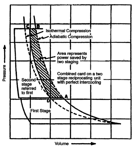
29. Why multistaging approaches isothermal compression
A multistage compressor divides compression into steps.
Between stages, an intercooler removes heat.
Benefits:
- Lower discharge temperature
- Lower total work
- Reduced pressure differential per cylinder
- Lower frame and running-gear loads
- Better volumetric efficiency in later stages
- Condensate removal between stages
The compressor reference identifies power saving, discharge-temperature limitation, and pressure-differential limitation as the main reasons for multistaging.
30. Adiabatic discharge temperature
An ideal adiabatic or isentropic temperature relationship is commonly written:
T₂/T₁ = (p₂/p₁)^(k-1)/k
Therefore:
T₂ = T₁(p₂/p₁)^(k-1)/k
where pressures are absolute and temperatures are Kelvin.
Actual discharge temperature depends on:
- Compressor efficiency
- Cooling
- Valve condition
- Pressure ratio
- Cylinder size
- Speed
- Gas properties
- Leakage
The indexed compressor reference provides a theoretical adiabatic discharge-temperature graph for air.
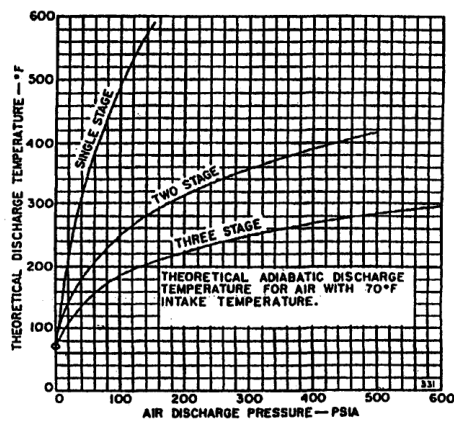
31. Multistage compression and gas-law reasoning
Suppose air is compressed from 1 bara to 16 bara.
A single stage experiences the full ratio:
r = 16
Two equal-ratio stages each experience approximately:
rstage = 4
Three equal-ratio stages each experience approximately:
rstage = ³√(16) ≈ 2.52
Smaller stage ratios generally reduce peak temperature and improve power performance when effective intercooling is provided.
The compressor reference explains that multistaging saves power, limits discharge temperature, and limits pressure differential.
32. Gas-law calculation rules
- Convert gauge pressure to absolute pressure.
- Convert Celsius to Kelvin.
- Use consistent units.
- State what remains constant.
- Check whether the gas is sufficiently ideal.
- Check whether phase change is possible.
- Confirm whether the volume is actual or standard.
- Distinguish mass flow from volumetric flow.
- Check the answer for physical sense.
- Compare the result with measured machine data.
33. Thermodynamics of Compression: Isothermal vs. Adiabatic vs. Polytropic Paths
To understand why marine reciprocating air compressors are designed the way they are, we must begin with the fundamental physics of gas compression. When a piston moves upward in a cylinder, it reduces the volume occupied by the trapped air molecules. Reducing volume forces molecules closer together, increasing their collision frequency against the cylinder walls, which registers macroscopically as an increase in static pressure.
However, compression does not merely squeeze molecules: the mechanical work performed by the piston shaft imparts kinetic energy to the gas molecules. This mechanical work is converted directly into internal thermal energy. How that thermal energy is handled during the compression stroke defines the three classical thermodynamic paths:
A. The Three Compression Paths on the P-V Diagram
- 1. Isothermal Compression (P · V = Constant, n = 1):
In an isothermal process, the temperature of the air remains perfectly constant throughout the entire compression stroke (T = Constant). For this to happen, every single joule of heat generated by mechanical compression work must be instantaneously conducted away through the cylinder walls into the cooling water jackets as fast as it is produced (Q = W, ΔU = 0).
On a Pressure-Volume (P-V) indicator diagram, the isothermal path forms a gentle equilateral hyperbola. Because the pressure rises at the slowest rate for a given decrease in volume, the area under the isothermal curve is the absolute minimum possible. Therefore, isothermal compression represents the thermodynamic ideal of 100% cooling perfection, requiring the least amount of electrical motor work to compress a given mass of air.
Work of Isothermal Compression (Theoretical Minimum Work)
Wiso = P1 × V1 × ln(P2 / P1) = m × R × T1 × ln(P2 / P1)
Where P1, V1 = Initial suction state; P2 = Delivery pressure; T1 = Constant absolute temperature (K)
- 2. Adiabatic / Isentropic Compression (P · Vγ = Constant, where γ ≈ 1.4 for air):
In a perfectly adiabatic process, zero heat is transferred between the air inside the cylinder and the external environment (Q = 0). The cylinder walls act as perfect thermal insulators. Consequently, 100% of the mechanical work done by the piston is converted directly into an increase in the internal energy of the air (ΔU = W), causing a dramatic, runaway surge in air temperature.
Because the air heats up rapidly during the stroke, its thermal expansion fights the piston. The pressure increases not only due to volume reduction (Boyle's Law), but also due to thermal pressure rise (Amonton's Law). On the P-V diagram, the adiabatic curve rises steeply above the isothermal line. The area under the adiabatic curve is the largest, meaning it requires the maximum mechanical work and power from the driving motor.
Work of Adiabatic (Isentropic) Compression (Maximum Theoretical Work)
Wad = γγ − 1 × P1 × V1 × [ (P2 / P1)γ − 1γ − 1 ]
Where γ = 1.4 for air; zero heat rejection (Q = 0); maximum work input
Theoretical Adiabatic Discharge Temperature
T2 = T1 × (P2 / P1)γ − 1γ
Absolute temperature in Kelvin (K = °C + 273.15)
- 3. Polytropic Compression (P · Vn = Constant, where 1 < n < γ):
Real-world reciprocating compressors can achieve neither pure isothermal nor pure adiabatic compression. In practice, reciprocating pistons travel at high speeds (typically 400 to 1,000 RPM). At these velocities, a single compression stroke lasts only 0.03 to 0.075 seconds. There is simply insufficient time and cylinder wall surface area for all the heat of compression to conduct across the cast iron liner into the circulating water jacket.
However, because the cylinder heads and liners are water-cooled (or heavily finned for air cooling), some heat is removed during the stroke. The real compression path therefore follows a polytropic process where the polytropic exponent n lies between 1.0 (isothermal) and 1.4 (adiabatic). In modern water-cooled marine compressors, n typically ranges from 1.25 to 1.35.
Real Polytropic Compression Work & Path
Wpoly = nn − 1 × P1 × V1 × [ (P2 / P1)n − 1n − 1 ]
Where n ≈ 1.25 to 1.35 for water-cooled marine reciprocating cylinders
B. Why Isothermal Compression Cannot Be Achieved in a Single Stage
Marine engineers often ask: If isothermal compression saves the most electrical power and keeps temperatures low, why don't we design compressors to be purely isothermal?
To achieve pure isothermal compression in a single cylinder, the machine would have to run at an impractically slow speed (a few RPM) with an enormous cooling surface area to allow instantaneous heat dissipation. A slow-speed compressor would be physically massive, weigh tens of tons, and deliver negligible cubic meters of air per minute. To achieve compact size, high capacity, and realistic weight, marine compressors must operate at speeds where compression is unavoidably polytropic, generating severe internal heat that must be managed by other thermodynamic means—namely, multistage compression with intercooling.
34. The Physical Limits & Hazards of Single-Stage Compression to 30 Bar
On merchant vessels, starting air systems require air receivers charged to a working pressure of 30 bar gauge (31 bar absolute) to provide the massive pneumatic torque needed to turn over large two-stroke and four-stroke propulsion engines from cold standstill.
If an engineer attempted to compress ambient atmospheric air (1 bar absolute, 30°C) to 31 bar absolute in a single cylinder, four severe thermodynamic and mechanical barriers would cause catastrophic failure:
Danger: Catastrophic Discharge Temperature & Explosion Hazard
Let us calculate the theoretical discharge temperature for a single-stage compression from 1 bara (30°C / 303 K) to 31 bara with a realistic polytropic index n = 1.3:
Single-Stage Temperature Calculation (31:1 Pressure Ratio, n = 1.3)
T2 = 303 K × (31)1.3 − 11.3 = 303 × (31)0.231 ≈ 303 × 2.213 = 670.5 K = 397.4°C
Under pure adiabatic conditions (γ = 1.4), temperature reaches an astounding 525°C (798 K)!
The Operational Disaster: Standard marine compressor mineral lubricating oils have a flash point between 200°C and 250°C and an auto-ignition temperature around 380°C to 400°C. At 397°C:
- Lubricating oil vaporizes instantly from the cylinder walls, leaving the piston rings dry and causing metal-to-metal scuffing and piston seizure.
- Vaporized oil undergoes severe thermal cracking, forming hard, abrasive carbon crusts on discharge valve plates. These carbon crusts prevent valves from seating properly, causing high-temperature discharge air to wire-draw back and forth, driving temperatures even higher (thermal runaway).
- Starting Air Line Explosions: Glowing red carbon sparks ignite the atomized oil-air mist, creating a violent detonation wave inside the discharge pipework that can rupture air bottles and kill personnel.
2. Collapse of Volumetric Efficiency
Every reciprocating cylinder has a physical clearance volume (dead space) between the piston crown and the cylinder cover at Top Dead Center (TDC). At a 31:1 pressure ratio, the high-pressure air trapped in this clearance space must expand to over 14 times its compressed volume before the cylinder pressure drops below 1 bar to allow the suction valve to crack open. The re-expanding clearance gas fills nearly the entire cylinder bore, reducing the effective fresh-air suction stroke almost to zero! The compressor would churn air back and forth without pumping any useful volume.
3. Excessive Mechanical Stresses & Running Gear Sizing
Mechanical piston thrust is governed by Force = Pressure × Piston Area. To draw in a large volume of ambient air, a single-stage cylinder must have a large diameter (e.g. 300 mm bore). If that large 300 mm piston is subjected to 31 bar pressure at the top of its stroke, the peak instantaneous thrust acting on the piston crown exceeds:
Peak Instantaneous Piston Thrust (300 mm Bore at 31 Bar)
F = P × A = (31 × 105 N/m2) × (π4 × 0.32 m2) ≈ 219,000 N
Imposes 22.3 tonnes-force of instantaneous mechanical shock onto gudgeon pin and crankpin bearings!
Transmitting 22 tonnes of instantaneous shock load into the gudgeon pin, connecting rod, bottom-end bearings, and crankshaft requires massive, heavy running gear, drastically increasing rotational inertia, bearing friction, and mechanical failure risk.
4. Prohibitive Electric Motor Power Consumption
Compressing in a single stage follows a steep, uninterrupted polytropic curve all the way to 31 bar. The area under this single steep curve represents an enormous expenditure of electrical work, demanding massive motor kilowatts and wasting valuable fuel in the ship's auxiliary generators.
35. Multi-Stage Compression & Intercooling Thermodynamics
Multistage compression completely resolves all four limitations of single-stage compression by dividing the overall pressure rise into two or more distinct pressure steps (stages), separated by an external heat exchanger known as an intercooler.
A. The Physical Mechanism of Intercooling
Consider a typical two-stage marine starting air compressor compressing ambient air from 1 bara to 30 bara:
- Low-Pressure (LP) Stage Compression: Ambient air (1 bara, 30°C) is drawn into a large-diameter LP cylinder and compressed to an intermediate pressure of approximately 5.5 bara (4.5 bar gauge). Because the stage pressure ratio is moderate (5.5:1), the air discharge temperature rises to a safe, manageable 130°C to 150°C—well below the flash point of lubricating oil.
- Intercooling at Constant Pressure: The hot 140°C air leaves the LP cylinder and flows through the intercooler (a multi-pass copper-nickel or aluminum-brass tube nest cooled by seawater or central fresh water). Inside the intercooler, heat is extracted from the compressed air at virtually constant pressure (neglecting minor friction drop). The air temperature is brought down to within 5°C to 10°C of the cooling water temperature (typically cooled back to 35°C to 40°C).
-
Volumetric Contraction: According to Charles's Law and the Ideal Gas Equation (P · V = m · R · T), cooling a gas at constant pressure causes its volume to shrink in direct proportion to its absolute temperature:
Volume Contraction Through Intercooling
V3 = V2 × (T3 / T2) = V2 × (308 K / 413 K) ≈ 0.745 × V2
Cooling shrinks air volume by ~25%, dramatically increasing density (ρ = P / RT) before the HP stage!
- High-Pressure (HP) Stage Compression: This cold, dense air enters the smaller-diameter HP cylinder. Because the air is pre-cooled, compression begins at 35°C instead of 140°C! The HP stage compresses the air from 5.5 bara to the final 31 bara (30 bar gauge). Again, because the pressure ratio is only 5.6:1, the final HP discharge temperature reaches only 140°C to 155°C, completely eliminating carbonization and fire risk!
B. Visualizing Power Savings on the Combined P-V Indicator Card
Refer to Figure 2 above. This combined indicator diagram represents the master thermodynamic justification for multistage compression:
- The Single-Stage Adiabatic/Polytropic Path (Curve 1 → 2 → 6): If air were compressed in one single stage to final delivery pressure, it would follow the continuous steep upper curve all the way to point 6. The total work done would equal the entire massive area under curve 1-2-6-Pfinal.
- The Multistage Stepped Path (1 → 2 → 3 → 4):
- Air is compressed in the LP stage along curve 1 → 2 up to intermediate interstage pressure Pi.
- At point 2, the air enters the intercooler. As it cools at constant interstage pressure Pi, its volume contracts, moving horizontally to the left along line 2 → 3 until it touches (or approaches) the ideal isothermal curve at point 3.
- From point 3, the cold, dense air is compressed in the HP stage along curve 3 → 4 up to final discharge pressure P2.
- The Shaded Area of Power Saved: Look at the triangular shaded zone enclosed by points 2 → 6 → 4 → 3 → 2. That enclosed area represents mechanical work that the compressor motor does NOT have to do! By simply removing heat between stages and shrinking the volume of the gas, a two-stage compressor saves approximately 12% to 15% in electrical power. In three-stage compressors (used for 100 to 200 bar systems), power savings exceed 22% to 25%.
C. Perfect vs. Imperfect Intercooling
| Classification | Thermodynamic Definition | Practical Marine Conditions |
|---|---|---|
| Perfect (Complete) Intercooling | The compressed air is cooled back down to the exact initial suction temperature of the first stage (T3 = T1). Point 3 on the combined indicator card lies directly on the isothermal baseline. | Theoretical standard used for thermodynamic calculations. Requires an infinitely large heat exchanger with unlimited cooling water flow at or below ambient air temperature. |
| Imperfect (Real) Intercooling | The air leaves the intercooler at a temperature 5°C to 15°C higher than the original ambient suction temperature (T3 > T1), and experiences a small friction pressure drop (ΔP ≈ 0.1 to 0.25 bar) through the cooler tubes. | Standard real-world marine operation. Point 3 sits slightly to the right of the isothermal curve. High seawater temperatures in tropical waters (> 32°C) degrade intercooling, slightly increasing HP compression work and discharge temperature. |
36. Optimal Stage Pressure Ratios & Work Splitting
Key Symbol & Variable Definitions
- rp (Stage Pressure Ratio): The ratio of discharge pressure to suction pressure for an individual compression stage (e.g. for the LP stage, rp = Pi / P1; for the HP stage, rp = P2 / Pi). The subscript p stands for "pressure ratio".
- Pi (Intermediate / Interstage Pressure): The static pressure of the air inside the intercooler pipework between the Low-Pressure (LP) stage delivery and High-Pressure (HP) stage suction. The subscript i stands for "intermediate" or "interstage".
- P1 (Suction Pressure): The ambient intake pressure entering the first stage (typically 1.0 bara atmospheric).
- P2 (Final Delivery Pressure): The high-pressure discharge delivered to the air receiver (typically 31.0 bara / 30 bar gauge).
- Wtotal, WLP, WHP: The total mechanical compression work, and the work done individually by the LP and HP stages.
A central question in compressor engineering is: At what exact intermediate interstage pressure (Pi) should the intercooler operate to achieve the absolute minimum total power consumption?
A. Mathematical Derivation for Minimum Work
For a two-stage compressor with perfect intercooling (T3 = T1) compressing an ideal gas along a polytropic path (n), the total work done (Wtotal) is the sum of LP work and HP work:
Total Work of Two-Stage Compression (Wtotal)
Wtotal = nn − 1 m R T1 × [ (Pi / P1)n − 1n − 1 ] + nn − 1 m R T1 × [ (P2 / Pi)n − 1n − 1 ]
To find the value of interstage pressure Pi that minimizes total work Wtotal, we differentiate Wtotal with respect to Pi and set the derivative to zero (dWtotaldPi = 0):
Derivation of Optimal Interstage Pressure (Pi)
Step 1 (Equal Stage Pressure Ratios): PiP1 = P2Pi
Step 2 (Cross-Multiplying): Pi2 = P1 × P2
Step 3 (Optimal Interstage Pressure): Pi = √P1 × P2
Minimum total work occurs when stage pressure ratios are identical!
This fundamental equation reveals three vital thermodynamic principles:
- Equal Pressure Ratios: Minimum work occurs when the stage pressure ratio in the LP stage (Pi / P1) exactly equals the stage pressure ratio in the HP stage (P2 / Pi):
Optimal Stage Pressure Ratio (rp)
rp = PiP1 = P2Pi = √P2P1
- Equal Work Sharing: When stage pressure ratios are identical, the mechanical work performed by the LP cylinder exactly equals the work performed by the HP cylinder (WLP = WHP).
- Equal Discharge Temperatures: Assuming identical polytropic exponents and perfect intercooling, both stages experience the exact same temperature rise:
TLP,disch = THP,disch
B. Practical Marine Calculation: 30 Bar Starting Air Machine
Let us calculate the design parameters for a merchant ship main starting air compressor operating from 1 bara suction to 31 bara delivery (30 bar gauge):
- Overall Pressure Ratio (R): R = P2 / P1 = 31.0 / 1.0 = 31.0 : 1
- Stage Pressure Ratio (rp): rp = √31.0 ≈ 5.57 : 1
- Ideal Interstage Pressure (Pi): Pi = P1 × rp = 1.0 bara × 5.57 ≈ 5.57 bara (4.57 bar gauge)
- HP Discharge Pressure (P2): P2 = Pi × rp = 5.57 bara × 5.57 ≈ 31.0 bara (30.0 bar gauge)
Notice how balanced this is: both cylinders work against an identical pressure ratio of 5.57, sharing the mechanical torque load evenly across the crankshaft throws!
C. Cylinder Sizing & The Stepped Piston Arrangement
Why is the high-pressure cylinder so much smaller in diameter than the low-pressure cylinder?
Because the compressor operates continuously in series, the mass flow rate of air (˙m, kg/s) passing through both cylinders must be identical. However, because the air entering the HP cylinder has already been compressed to 5.57 bara and cooled back to ambient temperature, its density is roughly 5.5 times higher than the air entering the LP cylinder.
Therefore, the volume of air that the HP cylinder must draw in during each stroke is only a fraction of what the LP cylinder draws in:
HP Cylinder Swept Volume Sizing
VHP,swept ≈ VLP,sweptrp ≈ VLP,swept5.57 ≈ 18% of LP Swept Volume
Explains why the HP piston diameter is so much smaller or arranged as a stepped tandem piston!
To achieve this volume reduction with the same stroke length (since both pistons are driven by throws on the same crankshaft), the HP cylinder bore is made dramatically smaller, or constructed as a stepped tandem piston where the LP piston crown steps down to an integral smaller-diameter HP piston extension.
Practise this in the question bank
- Air Compressor (motor) — 6 questions
Found a mistake, or something unclear?
Report it in a few seconds — it goes straight to the editors.
- Air Compressor Principle, Thermodynamics & Multistage Advantages
- Air Compressor Types & Classification
- Air Compressor Construction — Pistons, Rings, Valves & Running Gear
- Air Compressor Working — Cycle, Volumetric Efficiency, Coolers & Capacity
- Air Compressor Operations — Lubrication, Drains & Running
- Air Compressor Maintenance — Lapping, Clearances & Overhaul
- Air Compressor Safety — Relief Devices, Receivers & SOLAS
- Air Compressor Troubleshooting — Interstage Pressure & Fault Finding